Making mods to a Sony CDP-302

This may be asking for the moon, but what could I do to this old timer to perhaps make it a little better than it is. I have taken a pic of the inside if that helps. I'm fairly adept at modding analog stuff, but digital is unfamiliar territory for me. I might be beating a dead horse, but it just seems so well built compared to todays offerings I can't help but to try.

BTW: It works right now. I'm just looking for any tweaks/improvements I could make.

Thanks for any tips.

*Note: Picture is fairly large.
Sony CDP-302 internal pic.

Tango Hirata XE60-3.5S for sale

Used pair of early Tango Hirata (not the ISO version) XE60-3.5s for sale. Great for most of the single-ended application eg.2a3, 300b etc. They are in beautiful physical condition and of course works as they should. However their factory boxes and papers are long gone.

I am asking USD1500, inclusive of shipping via EMS worldwide. PM me your email address to send pictures.

Soldering difficult connectors

Hi All,

I have made a couple of DIY interconnects using inexpensive cable and KLH bullet, connectors. I think I managed to do OK with them but honestly the long term reliability worries me somewhat.

The RCA plugs use these tiny, flat connectors with U shaped prongs internally. They are flat, small, and have no hole to hook the wire through or around really. Looking at pictures online, the ones I had were definitely not curved and flat.

I'm just wondering, what is the soldering strategy of attaching a tiny wire to the end of a piece of metal when it barely has a place to put it, let alone tie it or put one inside the other?

Symmetrical amp clipping behavior - help needed

I have an amp design here, which evolved from non-symmetrical amps I already built in this thread.
So this is continuation, hopefully for the better.
See the attached LTSpice sim file, and screenshots (for 1kHz and 10kHz).
Everything seems to be working fine, except the clipping.
Looks kind of ugly.
Any help with improving clipping behavior (or anything else) in this amp would be appreciated.
Choice of transistors is determined by what I have (e.g. TTA/TTC, BD140, BC).
I simed it with different ones, to pretty much the same results. Also have higher voltage version with bigger fets,
but for this one I want to use IRF640/9640, as I have too many of them..

As it turns out, this thread evolved into "hands-on crash course in feedback stability", so keep reading if you want to
find out how to evaluate OLG, Bode plots, Phase Margin and Gain Margin.
For dummies.
Most recent schematic: post #69

Attachments

  • wdrhld_baby_beast.comp.hexfet.10mar2021.jpg
    wdrhld_baby_beast.comp.hexfet.10mar2021.jpg
    261.5 KB · Views: 653
  • thd_1.png
    thd_1.png
    25.9 KB · Views: 722
  • thd_10.png
    thd_10.png
    25.8 KB · Views: 633
  • fft_1.png
    fft_1.png
    25.4 KB · Views: 611
  • fft_10.png
    fft_10.png
    25 KB · Views: 605
  • sqr1.png
    sqr1.png
    37.7 KB · Views: 260
  • sqr2.png
    sqr2.png
    39.1 KB · Views: 258
  • clip1.png
    clip1.png
    39.9 KB · Views: 324
  • wdrhld_baby_beast.comp.hexfet.10mar2021.asc
    wdrhld_baby_beast.comp.hexfet.10mar2021.asc
    17.4 KB · Views: 87

Help needed

Since the beginning of the pandemic I have had engineering parts and test equipment essentially dumped on me as companies changed and people moved on to new lives. If I were rational most would have left as e-waste, but I'm not and I'm sure there are others near me who could find utility for this excess stuff, but Its more than I can handle alone.

Is there anyone in the Bay Area interested in pawing through piles of caps, resistors, transistors, IC's, tubes etc. to sort into useful piles and help find homes for it all?

PM me if interested.

F7 clone kit and WHAMMY PCB

1) First Watt F7 amplifier clone kit containing all parts to build a working stereo amplifier (jfets, Semelab mofsets, resistors, pots), two pcbs (one for each channel) and a schematic. Nelson Pass has not released the official schematic for the F7, so this is a best-guess circuit that measures the same but may not be identical. Power supply, panel or hook up components are not included, just the parts to stuff the boards.

$160 USD plus shipping.

About the kit: this was purchased from a diyaudio member in 2020. He did the hard work of understanding the circuit, testing it, sourcing the parts, measuring transistors and pre-adjusting the pots. You can find information from him and other members who reverse engineered this circuit in the F7 thread. In addition to the kit, I will forward an email from him with additional details about his build. He bought and measured extra parts to get enough working components, and I was lucky enough to snag a set made from his excess stock. He tested components in a working circuit, so they are not factory sealed, but were not otherwise used by him or me. I never started construction. Unfortunately, running a COVID home school for my children ate all my free time for the past year and created a backlog of projects. Neither the designer nor I am making a profit: the kit is selling for the cost of the parts.

A few important details: I will share the schematic only with the buyer and only after purchase. The "long and skinny” PCBs require a longer chassis than the diyaudio deluxe and do not use the diyaudio universal heatsink drillings. You will need to source your own chassis and drill your own heatsinks. There is a silk screen error in one channel's PCB documented in the information I will give you. One of the most difficult parts of building the F7 is biasing the JFETS. This is done for you via prematched and preadjusted pots, which must go in the correct position according to the instructions. You still need to adjust the bias current by ear or with measurement, so this is not "plug and play", but much closer than if you sourced parts yourself.


2) WHAMMY headphone amplifier PCB. This is the PCB available in the diyaudio store. I have too many headphone amplifiers and will not build this one.

Save a few dollars at $20 plus shipping.

Shipping to the USA will be via USPS and is affordable. Shipping outside the USA can get quite expensive and be very slow these days.

CALRAD CR-12TX , Triaxial's (rebuilt)

Goodday for those of you who are looking for a good pair of CALRAD CR-12TX , 12" triaxle speakers that have been Re-built , yep new foam rool suspension, cones ahave been coated with PVA style coating and firmed up using carbon fiber ribs. Twweter horn flares are Aluminium and have been damped using, plumbers putty. Tweeter are mylar diaphrams (original). 20 Watss RMS powr handling and the coil DCR's are both around 7.4 ohms on each, Vas is unknown but likely in the 8 cu ft range.
An externally hosted image should be here but it was not working when we last tested it.


Price is $165 for the pair. OBO

Shiiping from Calgary ALberta Canada Postal code is T3C2A1
Wieght is only around

Hammond transformers available NOS

Hammond transformers 167P100's &167P36 NOS

I have 2 x Hammond # 167P100 , 100vac secondary , center tap , 5 amps.
and
One Hammond 167P36 , 36 VAC center tap , 180 va.
All are NOS never been used , good condition.
Asking $120 for pair of 167P100's
and $35 for 167P36
Shipping from Calgary Alberta Canada , postall code T3C2A1
Payment via e-trans in Canada , or cashiers cheque from us. Will provide complete details including tracking numbers fro UPS shipping to US. Canada Post in Canada unless otherwise specified !
Thanks Rich Allan

Repair service for Braun Regie 550

Hi all.

OK. So here's the story.

1. I have 2 Braun Regie 550 receivers. I am a total sucker for these receivers, and I LOVE their performance and looks. I have the tape deck also, and now all I need is the turntable...ok that's another story.
2. One of them just decided to go into protection. Immediately upon turning on, the protection relay does not click, and of course, there is no sound at all now.
3. Before this, it was having a loud hum on all inputs. I replaced the filter caps (the big silver ones, or coupling caps?) in the power supply.
4. The hum went down a lot. But there was hum still in the phono -- engaging the phono stage gives a loud enough hum at just the 9o'clock position on volume. The hum increased with volume.
5. Very soon, the protection relay refused to click and the receiver has no sound at all.

6. The second Braun receiver has some loud scratchiness in the volume/bass/treble controls....Deoxited a couple of times. Still scratchy. Don't know if it needs anything more.

I am not very good at schematic reading, and would like to know if anyone wants to take on the project of fixing this, and doing a proper recapping of old caps.

** Schematic attached
** Service manual attached.

If anyone has ideas about possible issues I should look at, that is also something I am happy to try. Of course, I don't have any equipment to check amplifier bias and such.

Thanks for reading! Comments welcome!

Attachments

Sub woofer for Quad ESL 57s with active crossover

I have a pair of stacked quads which I adore refurbished using Sheldon Stokes brilliant book. However my listening room is very large - about 10m x 8m with 4m ceiling so that the lower bass lacks ‘punch’.
I just picked up a pair of old but good B&W 801s and wondered about pursuing an active crossover set up with their enormous drivers.
Has anyone tried anything like that.?

Help assess Impulse Response of LXminis

Hello,


I started with using REW and UMIK-1 microphone to understand my room behaviour. On the way, I measured my LXminis. The Frequency Response is correct, but I'm puzzled with the Impulse Response measurement that does not looks at all like a pure dirac. See below:
- starts with a negative 100% (instead of expected positive),
- then a positive 80% (OK for a small "overshoot" but not that much).


Is this normal and related to the 2 drivers and the inverse polarity of the Full Range (by design inverse polarity to be in phase with the woofer at cross-over freq) ?


Is this abnormal and I should investigate ? In REW documentation, the picture for IR measurements shows a nice positive single peak, as expected, with only few ripples.


Nota, the Freq Response at crossover frequency is clean with no dip, which confirms that the woofer and the Full Range blend well and are in phase at that point.


This may be a quite stupid question, sorry for that. But willing to learn !


JMF

Attachments

  • LXmini impulse 3ms nearfield.PNG
    LXmini impulse 3ms nearfield.PNG
    95.2 KB · Views: 234

Oscilloscope and high voltage

Hi guys.
I bought a pc based oscilloscope ISDS205A and now I study to use it.
I have a problem with a small standby pulse transformer, which of the primary coil should have < 300V.

In the user manual is said:
2, Oscilloscope with Probe: X1 CAN MEASURE -5V TO + 5V VOLTAGE, X10 CAN MEASURE -50V to + 50V.
3, The Measurement of the Electric Supply 220V / 110V IS DIFFERENT FROM THE NORMAL WAVEFORM MEASURMENT AND NEEDS TO BE RE-MEASURED BY AN ISOLATED TRANSFORMER.

Does that mean if i buy probe x100 I will be able to measure up to 500V ?

Sorry for the lame question,
I am learning now.

Cheers!

Newbie building subs with SB23MFCL45-8 drivers.

Hi Everyone

As the title suggests, I am completely new to building subs and wanted some advice on how to make this learning process as painless as possible!😀

I will try and keep this short but understand that most people here like a bit of background to help determine the best direction.

I should explain that I am currently constructing some floor standers, that started out as mini monitors (Gorens excellent Revelation mk2 www.audioexcite.com >> Revelation Two – Monitor MkII ). A house move and a bigger living room meant that 5.5" woofers just weren't enough! so they are being put into floor standers with 2 x 18w units each to beef up the low end. (active x-overs from 18w to 15w and Gorens passive x-over for the 15W to tweeter). I have built cabs with various panels that can be moved around or removed so I can play with different volumes and experiment with ported or sealed. Luckily I have a cousin who has built active speakers for some years now, helping me with this side of things (building the amps, measuring etc), but he has no experience with subs.

The reason why I am thinking of adding subs to this is because a bit more controlled low end is always a good thing 😀 and I already have 4 x SB23MFCL45-8 drive units (long story).

So now for the questions.....!


I am thinking that maybe a pair of sealed stereo subs, each with an up and down firing driver could be a good choice? (or not? - opinions please!)
Also what would be a good amp for this driver? The mains are going to be running some cheap but nice 125W modules that my cousin uses and rates highly, but I am not sure if this will provide enough grunt for subs?
I am also thinking that as LF tend to excite room modes more, maybe I should look at DSP to try and control this? (Mini DSP 2x4HD maybe?)
If I build these subs, would I be best making the mains sealed to help make integration with the subs smoother? (is that a correct assumption?)

The room they will be going into will be roughly 20sqMetres.
My main priority is clean fast bass rather than huge SPL for mainly rock and electronic music (Pink Floyd, Massive attack, Foo fighters etc)

Sorry if this is a long post. Any help/advice is welcome.

Big tubes on low power

Hi,

Suppose we take a russian GU72 and run it on perhaps 320V and 20W instead of 600V and 60W or so, could we expect any ill effects on tube life?
I´m asking because I seem to recall something a friend mentioned long ago, something about certain tubes relying on some sort of auto-absorption instead of normal gettering to deal with outgassing. I´ve tried to google the subject without any useful results.

Electrolytic Capacitors for NAD T973?

It turns out that Mouser and Digikey don't have anything in 34-35mm diameter that fit the requirements for 80 VDC and 22K uF.

The caps I need to replace are 34x80mm and 34x100mm. 15K uf and 22K uF both at 80V.

Closest I can source at Mouser is 40mm diameter, which will bump into the bus bars on the PCB and will prevent fitting the plastic cover over the far end of the cap bodies, which secures it from vibration, to chassis.

I found some similar caps in screw terminal, but these are four terminal snap ins that solder directly to the PCB. Originals are NAD-branded.

Who sells these?

GB: Round #7; Fo-Felix AC Filter

**We're on round #7!!!**

I've confirmed how to order parts, made sure it isn't an issue for Comocos. (please no more requesting samples)

So over the years people have asked about the old version, made by someone else.

It's probably time for an updated one. This one is a bit different. You may notice it does not have following capacitors after the choke. I have tried both ways, and my preference is strongly without the following X2 capacitors. Also the capacitors prior to the choke are not varied in size because overall capacitance is more important - and they won't randomly resonate with each other.

The other major change is the addition of bypass resistors for the chokes. These don't ruin the filtration, but they do a good job of quieting the chokes that can get excited by different combinations of things on the mains.


Fo_Felix_R2_Public_preview2.png


Gen1 w/comoco's
IMG_1974_1_22.jpg


Here's how it is different in settling time from the original.
Fo_felix_vs_felix.png


Here's a comparison between resonances.
Fo_felix_vs_felix_resonance.png


*2oz copper PCB (1oz is standard)
*Weco 983ZD terminals, copper alloy and can accept 2 wires for daisy chain. These are also safer, particularly if you use solid core wire that otherwise likes to make cold solder joints you can't see.
*X2 rated capacitors for safety, 4x 0.47uf. They are alternated for CFC (capacitor field cancellation).
*Discharge resistor for X2 capacitors
*Coilcraft Comoco choke w/fuse or Bourns 8120/8121-RC choke w/o fuse & 15/16A/20A(*) max sockets
*Fuse clips are beryllium copper (good for 30A)
*120/230v operation (parts & pcb)
*Mounting holes are sized to work nicely with M3 screws and standoff kits
*Size: 2.25x4.25in

The Weco 983ZD are preferred terminals, but not always available as individual sale. For this reason I'm going to include them in the price of PCB, so that I can meet min order requirements for them and save everyone the shipping.

Price: $13ea ($9 per filter board same as original, $2 per Weco, 2 needed per board)

Shipping: $9 US, priority USPS box
$16 CAD
$17 General international padded envelope (prices may vary due to a crazy world)

If ordering over 4x boards there may be an additional $10, depending on destination.

Need 32 filter board commitments to order.

lordvader 3
Knuds1 4
docjrev 6
Dadbeh 2
gary s 3
wirewiggler 3
JRKO 4
DaveM 4
rtate 3
mrloud 3
loWfi4evR 2
ccliu 2
sampsonite 6
pwagner 4
chiily 3
webber 4
skunark 4
turion64 3
32y0 4
jam econo 4
pistollero 4
jack_b 4
ericimage2 5
Chilkoot 4
dualuxe 1

Converting single speaker terminal to tri-terminal

I have an amp with single speaker terminals, I would like to add two more terminals as I have tri-wire speakers and a sub that connects via speaker level inputs.

Planning to make a copper plate that I can attach like a spade with two holes on the side to to connect two additional terminals. The existing terminal has enough clearance to prevent the new terminals from hitting the back cover.

My question are.
1. Is copper the best material for the plate?
2. Do i need to have the copper plated?
2. How thick would the plate need to be ?

Attachments

  • speaker terminal copper plate.png
    speaker terminal copper plate.png
    62.9 KB · Views: 103

Can someone explain how a.FHXL "works"? Basic acoustic engineering?

I am nearing completion of building a FHXL. I have no idea what the horn is, or why this has its particular design. It would appear that the driver is placed so that half of the sound "goes" over the top into a wedge shape that dead ends. What is the purpose of that wedge? What do the slopes sides do, and why are they critical? What dimensions are cricical? What is the purpose of the fill, and how does fill "work"? If anyone can provide me with a basic understanding I would appreciate understanding the "why" behind the design.

Thanks

3-Way OB - get the best out

Hello!

I plan to build a 3-Way Open Baffle and want to get the best out of it. The goal is to make compromises that do not limit the sound quality to much.

My wishlist 😀

- Overall good dispersion (horizontally and vertically [WMTMW?]) with a smooth target curve (see Toole)
- Transient XO passiv
- Flat response
- Enough low distortion

I dont hear loud music (never more then 90db), because of my neighborhood.


General Problems with 3-Way OB are that one driver can only play for 2-3 Octave. My solution so far:

Bass- Low Mids:
Some years ago i have seen a speaker that goes incredible low in an open baffle because of a stimulated movement of the complete baffle (there was made some acceleration measurements). Click here...
For my bass section and the low mids i will use 2 or 3 of the Monacor SP-225 per side. (Probably i have to make some test with different baffle-sizes)

I think i could use the SP-255 in this way from 20Hz to maximum 600Hz!


Tweeter:

I think the best solution we can see with the BG NEO 3 (vertical position) on the Aino Gradient Speaker.
Alternative....
.... Radian LT2, Dayton PTMini 6 (They aren't able to crossover so low like Neo3 and if crossed higher its harder to get a smooth vertical dispersion)

..... Peerless OC16SC04 (Higher crossover-frequency and most worse dispersion of all alternatives because of big dipol-width at 7-8khz)

..... Peerless TC5FC02 (At Cone Breakup probably loose of a good dispersion on the baackside of the driver at 5 khz. Compared to this the Neo3 will hold up till 7 khz)

Therefore i think the best selection is the Neo3 (additionaly it has a good reputation) and when we need a better distortion because of a low crossover point probably the TC5FC02 could be a second option!


THE MOST DIFFICULT PART - WHAT COMPROMISES TO DO?
Filler (600Hz-2,4khz):

If we go to ask for the best dispersion, we take 4 of the Filler in a
W
MM
T
MM
W
configuratioin. The best 1,5" i have found:
1,5" Peerless by Tymphany TC5FC07-04
Alternativly Dayton Audio DMA45-4 but not loud enough.

Or only two of Tang Band W23-1287SI

As Info for the Peerless driver, the 'd'Appolito crossover-frequency would be 570Hz and 2,2khz. With these little drivers i can simulate a very nice vertical and horizontal dispersion.

Or is distortion and dynamic that bad, that we should go for something bigger?
Other Ideas?


Best regards, Tomas

Replacing 9 speakers B52 matrix 2000. I need help please.

Hi everyone,

I have 9 B52 Matrix 2000 systems, where I daisy chain them all to make this huge sub wall. Its about time to service them and I was under the impression that I could get more out of these by upgrading the driver. Someone recommended the Faitel Pro HP1010, or 18 sound 18’s because they can handle what the amp is feeding.

Currently the amp I believe provides 600w to the sub channel and 600 is spilt between the 12” highs. So my question is Is there a driver I can put in this box that will hit more powerfully, efficiently (less heat, friction), and lower than what is in these now? I think some of these are loaded with FSW or FTW eminece’s, rebadged.

Or can you recommend a new system that will crush this setup, (everybody always screams bassboss😀) That I can use 3 20a circuits.

Thank you so much!!

First Subwoofer, considering a PR

Hi all,
I've been thinking about doing my first small-medium subwoofer build and I'm hoping someone would be kind and patient enough to critique what I've come up with so far. This is a bit long winded as I'm trying to talk my way to a decision.

My project goal is for a -3dB in the mid-30s, with an overall volume less than 2cf. Maximum SPL isn't a priority. I already own a Dayton 100W plate amp that I'll start the project off with, but probably upgrade in the future. I have a budget of $200 or so for drivers/ports/etc, and I'm in Canada so driver selection tends to be a little more limited but Solen.ca is usually my go-to. I mostly played around with the Dayton Audio DCS255, DCS305, RSS(210/265/315)HF, and MX10.

I've already crossed sealed boxes off my list as I know I can't meet my goals without a massive box and/or DSP which I don't have the ability to do right now.

Finalist 1
Driver : Dayton DCS255-4
Box : 1.8cf, tuned to 32 Hz
Port : 4" x 16" round
Total Volume : 2.3 cf (includes port)

Ported seems like the obvious choice so this is my control, but when including the port my box volume tends to get larger than I want. This ones a bit large for me but I think I could make it work. Digs deeper than I need but overall pretty happy.
GREEN - 1.8cf DCS255 Ported.png

Finalist 2
Driver : Dayton DCS305-4
Passive Radiator : 1xRSS315-PR
Added Mass : 200g
Total Volume : 1.8cf

I was inspired to look into PRs when I came across the Meniscus Baby Boomer. I tried to match their claimed 30Hz F3 at 1cf but couldn't even get close. This was my best attempt using a single PR, and the PR costs more than the driver which seems a bit silly for me to consider and makes this the most expensive option. I'd also prefer dual PRs for the force cancelling property.
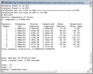
RED - 1.8cf DCS305 w RSS315-PR.png

Finalist 3
Driver : Dayton DCS255-4
Passive Radiator : 2xDS315-PR
Added Mass : 200g
Total Volume : 1.3cf

Really happy with how small this is, but a bit of a hump in response. Might increase the box size a bit to try and get rid of it. Cone excursion makes me a touch nervous too but its at such a high power level I don't think it's a realistic issue.
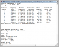
ORANGE - 1.3cf DCS255 w 2xDCS315-PR.png

Finalist 4
Driver : Dayton DCS305-4
Passive Radiator : 2xDS315-PR
Added Mass : 300g
Total Volume : 2.0cf

The added mass is right at the limit of what Greg at Dayton Audio said was "safe" but it still makes me a bit nervous. Excursion limits are under control and it digs nice and deep.
BLUE - 2cf DCS305 w 2xDS315-PR.png


My current front runners are 3 and 4, with 3 taking a slight lead due to the smaller size. I might be able to tweak the sizes of both to get excursion and added mass lowered a little bit but I'm curious what I'm forgetting to consider, and what the more experienced individuals would do differently.
ALL.png

How to disable bluetooth reception on TPA3116 board?

I bought this Board with Bluetooth 5.0:

img_20200816_09315018tjjk.jpg


which works great but unfortunately it is always possible to connect devices even when the 3.5mm Aux is connected.
Is ist somehow possible to disable Bluetooth (preferable temporary by switch
disconnecting antenna or something)

The Bluetooth Chip is an "JL" AS20BP00966-25A4 "JL" stands for ZhuHai JieLi Technology Co (珠海市杰理科技股份有限公司-珠海市杰理科技股份有限公司|杰理芯片)

the chips is likely either an AC6905A or AC69025C (most likely last one because of BT5.0)

the chips would have the following pinouts:

201863011461498090.png
5534324500_1563357318.png

System tuning vs Perception and Finding Neutral

OK, I subscribe to a more scientific approach to the idea of what SQ is...In a perfect world a Razor flat system measurement at listening position probably would interest me. etc etc bla bla bla....Perfect flat is not achieved in our rooms (mastering studios control rooms etc) but a best as possible of maybe +/-1.5db in a really critical listening environment? +/-3db elsewhere? I dunno...whatever is possible is fine and not my issue. We use measurement microphones to tune systems. A microphone is not the ear, and there are enough differences to start a whole, other, debate lol....non the less...my point is this! Why wouldn't I be better off, tuning my system, aiming at as flat as possible, using my ear.....instead of a microphone....my thinking is that everyone has there own personal "frequency response" and that with practice....you would achieve an even more natural system FR, than a microphone could....

Maybe using a signal generator?

I can't be the first person to have thought of this and I am curious to where this discussion goes.

Heatsink tempertures/transistor performance

Ive been measuring the temperaturs of the heatsinks on the amplifiers ive neen working on over the last few months, and they are all very different, but the one im working on at the moment has a very high temperature (53c)


most i have worked on get up to at most the mid 40's


can this affect transistor performance and eventual quality of output?


so a bit like a PC processor, the hotter it gets the less efficient, without the heatsink and fan it would soon fail, as would the transistors
with the processor it slows as it gets hotter, or too hot and i wondered if the same could happen to BJT'S?

D&B D12 amp and Q1 loudspeaker matching

Very newbie question here. I am buying my first line array for small venues (<1000 people).

The Q1 is rated 400W RMS @ 8 ohms. The D12 is rated 800W RMS per channel @ 8 ohms. So in theory, the D12 is able to power exactly 2 loudspeakers per channel. Am I right? The 2nd loudspeaker will be connected in the line-thru of the 1st loudspeaker, and putting the D12 amp in Q1 preset should do the correct impedance and crossover settings, right?

Just want to make sure I am not underpowering or overpowering the speakers.

Thanks

  • Locked
AEM6000 Based 50W Amp

The AEM6000 is an extremely well regarded amplifier making use of Hitachi
lateral MOSFETs. It was designed by David Tilbrook as a successor to the
ETI477, and published in Australian Electronics Monthly in the nineteen
eighties.
With changes in availability of components, the AEM6000 is now extremely
difficult to build. The amplifier was designed prior to the widespread use of
modelling tools, so is not optimised. Additionally it makes use of a large
single-sided PCB, with through-hole components throughout, like most kitset
amplifiers of the period.
This marks my fourth iteration of this amplifier. My first was reasonably faithful
to the original, differing mainly by substituting 2SK1058 and 2SJ162 flatpack
lateral power MOSFETs for the TO-3 devices in the original, plus substituting
an SST-404 dual JFET for the original input JFET. Iteration two was simply a
50W version of iteration one. This and the iteration three design (100W) alters
the topology slightly, dispensing with the differential-symmetrical VAS stage in
favour of a simpler non-differential stage. VAS and second stage transistors
are higher-performance 2SC3503 and 2SA1381, and the compensation
networks and biasing is optimised for increased amplifier speed whilst
reducing quiescent consumption


Power supply 4x4700uF. Bias 65mA,offset 5mV.


Specifications
Power handling: 50W RMS into 8Ω load.
Frequency response: +/- 0.1dB from 20Hz to 20KHz.
Gain 16 (stable with gain as low as 6).
Distortion + Noise: <0.0005% (1KHz, 0.1W to 50W into 8Ω).
<0.003% (10KHz, 0.1W to 50W into 8Ω).
Noise (input referred): 8nV/√Hz (measured at 10KHz, input shorted).
Slew rate: 10V/μs
Input impedance: 100KΩ (set by resistor).
Size: 75mm x 50mm PCB.
Power supply requirement: 2 x 40-60V DC. Lower voltages possible.
Idle power: 5.6W with +/-40V supply.

Price 90€

Attachments

  • IMG_20210705_141856.jpg
    IMG_20210705_141856.jpg
    403.9 KB · Views: 330
  • IMG_20210705_141846.jpg
    IMG_20210705_141846.jpg
    287.4 KB · Views: 327
  • IMG_20210705_141904.jpg
    IMG_20210705_141904.jpg
    387.9 KB · Views: 322
  • IMG_20210705_142413.jpg
    IMG_20210705_142413.jpg
    325.1 KB · Views: 319

Eton silk some vs the Magnesium Ceramic Dome?

Good afternoon everyone..Happy 4thof July. So I have never used a Eton tweeter before? I have use seas textile domes.and other planner and tweeter's and the L.G. metal some tweeter's from the past..So I have a few questions? I would really like to use the Eton magnesium ceramic dome model number 29HD2. I also like the sound of the silk Dome model number 28SD1. So can anyone tell me how the Magnesium Ceramic tweeter's sound like?Are they bright or tinging sounding? Thanks Jeff

Converting active monitors to passive

Hi everyone

I have these Neumann KH120 studio monitors, I quite like the sound but there are some reliability issues.

A while ago one of the monitors died. The problem lies within the smps.

Before that I had a customer bringing another one with the exact same problem, and on the internet there are several reports of smps failures.

I am not inclined in paying the official repair centre to fix the monitor and then having the same problem again at some point in the future.

I won't get much money for the broken speaker so I am starting to think I could have a play with it removing the whole psu + amp board and converting the speaker to passive.

I am totally new to crossover design so I am wondering wether this project would be worthwhile at all.
Very keen in knowing any opinions from who is more experienced in this subject

Here are some specs for the KH120 active monitor

NEUMANN

Breakups are the hardest thing to do!?

I've always wondered about how far I should drive breakups.

Some say 20dB is enough, others say 30dB, others go for 40dB or more.

after the driver (eg. Tweeter) overlaps, how much does masking affect the ability to hear these breakups?

Here's my driver + LP filter. Measurement conditions 0.5m, on baffle. Equivalent to 90dB/1m.


Are my breakups adequately suppressed? Perhaps this is one of those things where I need to test empirically with a DSP...

Attachments

  • PTT6.5 on baffle.png
    PTT6.5 on baffle.png
    106.1 KB · Views: 544
  • PTT6.5 on baffle distortion for 90dB@1m.png
    PTT6.5 on baffle distortion for 90dB@1m.png
    373.9 KB · Views: 514

Full Range/HF vs Traditional Tweeter

My journey of using small full range drivers for HF duties has only started in the last year or so. Currently using Fostex ff85wk/SB Acoustic SB13PFCR25-8. Presently I'm crossing high but am also experimenting crossing low around 350 or so. I realize I might be talking heresy but for those that also listen to a lot of classical music, have you found the sparkle of strings and brass slightly veiled when compared to a traditional tweeter? My lineup of traditional tweeters involves a Focal TC90TDX and some Elac products. My implementation of the Fostex may be lacking and I have no measuring/designing capability other than what I can plagarize from forums like this. However, I do have a little background in listening because I was a public school band director for 36 years. Thanks for any and all suggestions.

James from Australia

Hi,

Live in Western Sydney, Australia.
Long time reader and almost first time poster. Have been quietly assimilating information from this and a couple of other great forums.
Several months ago, purchased and built the Elekit Amp and Pre-amp, with upgrades and most recently the Lundahl transformers from Victor. Built birchply bass reflex speakers using the Super 15's from Audio Nirvana in an Ambience set-up. Built a PC with a EVGU audio card, lots of storage and generally play Flac files via JRiver, which works well as I've networked it to be available on several devices/bluetooth speakers throughout the home. Love the phone's ability to remote control the music from anywhere in the home. Also have a Planar turntable (entry level) that sounds a lot better than I think it should.
Room set up isn't ideal (5.5m X 6.5m with a vaulted ceiling) but I hope to move it all to a more ideal area on the near future.
I have a Richtor sub woofer (stolen from my home theater room) and use it with the bass plugs in, along with recently building 2 of the bucket subs which sit in each corner of the room out of the way, driven by a fairly basic dayton audio plate amplifier (they just add that subtle fill-in bass).
I've most recently purchased a Umik mic and started doing measurements, trying to understand REW and adjusting settings in JRiver. Have tried a couple of sets of tubes and gone back to the original ones for the measurements.
I think it's sounding better than ever and continue to thoroughly enjoy the clarity and sound stage as I tinker along...

James

Attachments

  • IMAG0309.jpg
    IMAG0309.jpg
    979.5 KB · Views: 105
  • IMAG0400.jpg
    IMAG0400.jpg
    811.7 KB · Views: 136
  • IMAG0407 1.jpg
    IMAG0407 1.jpg
    664 KB · Views: 92

QQ: Elevated heater wires - twist pairs together or keep separate?

I have a design I'm currently designing the build out for. It's a cascode with B+ of -320V to +320V thus the design has separate heater supplies to stay within the heater-cathode limits.

Is there any benefit from twisting/platting/tying the different heater pairs together?

The only issue I could see is ensuring the conductor to conductor insulation is high enough (ie from the lowest heater reference to the highest taking into account any AC peaks). Given they're running off separate isolated secondaries the only other issue is a small amount of capacitance.

It would look neater..

Nord nc500mkll DM. Problem Help please

Hello
I have bought a Nord nc500 from my friend butt sadly he dropped it the floor with the male XLR connectors in so it broken pretty bad
The cable inside on the XLR did loose and I can't understand how to get them back
I take som picture and hope someone know how to do!?
Vit for me is the signal bit is the light blue that to or........?
I know how to welder to the XLR , but I don't want to brake my amp.
I'm a hobby electric fixer so I can fix some stuff (I hope this)

All answer will make my day
Tanks PETER from sweden

Attachments

  • 16254623091645542500528104667782.jpg
    16254623091645542500528104667782.jpg
    488.2 KB · Views: 67

Selling Tango NC20F Interstage Transformers

For sale is a good working pair of Tango ISO NC20F interstage transformers.
Specifications easily available if you Google. They are currently installed on my amplifier. Going to decommission my amp. They are the best interstage transformers i have used so far. Send me a PM with your email if you want see some pictures.

US$850 + delivery cost depending on where you are and the service you choose. Paypal will be the mode of payment.

Next steps: grid and supply chokes for C3g drives 45B

My monoblocks are progressing nicely. Of course, I would like to advance the cause and tweak the schematic. As a baseline for the monoblock sounds, listening is non-fatiguing, taught bottom end (though not extended as I would like), smooth top end. Tonality is to my liking, natural and no extremes.

But, there is a slight bit of veil over the sound. Just the slightest opaqueness. So slight. So, I have a few ideas that may help remediate this issue. I am considering 3 alternatives, possibly all 3 eventually. Here are some ideas:

1. Replace the existing 100K grid resistor to a grid choke on the C3g.

2. Insert a new choke in front of the RC network feeding the IT / C3g.

3. Insert a new choke in front of the Russian 50uK Ultrapath cap which feeds the OPT.

All 3 of these option are highlighted with the blue boxes on the attached schematic.

I need your thoughts on these 3 options. Are these option expected to materially improve the monoblocks?

Thanks in advance.

View attachment C3g-45B 6.29.21 copy.pdf

Ground hum through speaker

Hi everyone,

I have a power amp that has ground hum coming through the speaker of one channel, even with nothing connected. It’s not loud, just about audible from listening position. I have attached a picture of the inside. The channel that’s humming is the speaker output nearest to the power input.

I’m not an electronics expert, but I have tried a few things. I removed some zip ties and moved the power cable away from the audio output cable. I have also used a chop stick to check for any loose components but found none.

Do you have any other ideas to try? I recognise that playing around with certain aspects of the amp can be dangerous, and I will be sure to discharge caps and anything else you suggest.

Thanks.

Attachments

  • IMG_20210622_190215556.jpg
    IMG_20210622_190215556.jpg
    584.7 KB · Views: 190

5x LME49811, 4x Panson's PCBs, Thermaltrak

I've had these since 2010, but at this point I don't think I'll build an amp with these.


(Although it's enough parts for 4 channels, so that would be one cool use case.)


So for sale here are:


5x LME49811


I got these as samples direct from National Semi back in 2010.


I think I also still have the printed invoices with my name on it, if that's enough proof of these being genuine, although I'll have to go to the storage to find it.


--


5x MJE15030G
5x MJE15031G
5x NJL3281DG
5x NJL1302DG


These are the power transistors to be used with Panson's circuit for example. I got these as samples as well from ON Semi.


--


And 4x Panson Audio Labs PCBs 'Compact Series' V2.1


Compact Series


--


The price for everything is 85 EUR + shipping and PayPal fees.


I don't want to divide it up and sell only select parts, maybe if there are two buyers who want to buy 2 channels worth of parts each.


Thanks.

Laplace transfer function, poles and quality factor

Hello,
I am working on my theoretical skill, and I struggle a bit understanding the geometric interpretation of s-plane regarding eigenfrequency (natural frequency ?) and quality factor.


On this document (cf screenshot), I read that poles at constant frequency move on a circle when modifying the quality factor?
Is it because of this "natural frequency" term ?

It goes strongly against my intuition that constant frequency is equivalent to constant imaginary part of the pole.


http://jahonen.kapsi.fi/Audio/Papers/Equalization.pdf

I am understanding wrong ? is the document a bit inaccurate ?

Would you have some recommendation about resources I could use to understand those thing ? (signal theory, linear stuff, DSP, and so on). I am not too scared of maths, but I really enjoy pedagogical stuff that gives intuitions.

Thank you very much 🙂

Attachments

  • Screenshot 2021-07-01 at 18-08-30 Equalization PDF - Equalization pdf.png
    Screenshot 2021-07-01 at 18-08-30 Equalization PDF - Equalization pdf.png
    98.2 KB · Views: 153

Toshiba SC - 335 and Toshiba SY - 335

Firstly, may apologies as I know very little about musical equipment, and I hope this is not in the wrong thread, but here goes,

Las week i purchased an old sound system. Brand is Toshiba (model number listed above) and it also came with a turntable.

When I brought it home to set up, I noticed the turntable does not have a needle for playing records (stupid, I know, but like I said, I am totally unfamiliar with all this) Are needles easy enough to come by? Do I need a specific one or are there generic ones I can pick up?

Also, when I brought it home and set it up, I tested the radio on it, it works fine but it seems to be stuck on full volume, which is pretty loud to put it mildly. I am looking at the back at all the cables and I may as well be looking at heiroglyphs.

Could anyone please help me and shed some light on these issues?

Thanks in advance,

Stefan

value of record sales in 2021 to surpass CDs

wow!

How vinyl records are trying to go green - BBC News

“There were 22 times more vinyl albums sold in the UK in 2020 than in 2007 - with sales leaping from 210,000 to 4.8 million.
The most recent figures from the British Phonographic Industry reveal sales grew by more than 30% in 2020 alone, bringing in revenue of more than £86m.
For the first time since the late 80s, the value of record sales in 2021 is expected to surpass that of CDs - although it still lags way behind digital streaming and downloads.”

And now we have to worry about the environmental impact, something that was not an agenda item back in the day.

LTspice models for Sanken 2SC6145/A2223

Apparent deficiencies of these models:

The 2SC6145 model has higher apparent Re at higher currents due to difficulty in modeling the curve in the datasheet. Furthermore, the high value of Nk may cause convergence or solver errors. Removing Nk should fix this, and the majority of Hfe droop is due to quasi-saturation anyway.

(I'm sure there are more deficiencies, but those are the apparent ones.)

.model 2SC6145-Y_kq NPN ; Revision 3 by keantoken - March 1 2019
+ Bf=93 Br=8 Re=8m Rc=16m
+ Rb=4 Rbm=0 Irb=0.3 Vaf=1000
+ Is=5p Ise=200f Ikf=200 Nk=1.9
+ Rco=0.68 Gamma=255n Vo=100 quasimod=1 Qco=100p
+ Tf=2.45n Cje=9.7n Cjc=880p Vje=0.68 Mjc=0.48 Fc=0.9
+ Xtf=30 Itf=15 Vtf=0.95 Xtb=0.9 Eg=1.16
+ Vceo=230 Icrating=15A mfg=Sanken
.model 2SA2223-Y_kq PNP ; Revision 3 by keantoken - March 1 2019
+ Bf=99 Br=8 Re=10m Rc=18m
+ Rb=2.38 Rbm=0 Irb=0.9 Vaf=500
+ Is=3.5p Ise=50f Ikf=3 Nk=0.15
+ Rco=395m gamma=14n Vo=30 quasimod=1 Qco=100p
+ Tf=3.65n Cje=8.3n Cjc=1.6n Vje=0.68 Mjc=0.48 Fc=0.9
+ Xtf=50 Itf=110 Vtf=2.6 Xtb=1.4 Eg=1.16
+ Vceo=230 Icrating=15A mfg=Sanken


Revision 3 - Updated Ft behavior with measure capacitance values thanks to astx.

Attachments

  • 6145-datasheet.png
    6145-datasheet.png
    91 KB · Views: 542
  • 6145-model.png
    6145-model.png
    15 KB · Views: 542
  • 2223-datasheet.png
    2223-datasheet.png
    98.5 KB · Views: 535
  • 2223-model.png
    2223-model.png
    15.9 KB · Views: 525

Sanken 2SC4883 and 2SA1859 SPICE models with quasi-saturation

I like the C4883/A1859 from Sanken, and have tried to model them well using the datasheet. It was tricky, but I'm pretty satisfied. I matched Vbeon, Ft, Hfe and quasi-saturation. Adding quasi-saturation makes Ft and Hfe MUCH more accurate, so I'd say this is in a new league of SPICE models.

The behavior shown in the datasheets is what I modeled, so I'm not sure about Early voltage or Hfe slope at higher voltages, but I think everything is close enough for a practical simulation, especially with quasi-saturation added.

Notice that the Vbeon curve on the datasheet specifies Tc=25C. If Tc is held constant, that means Tj increases with Ic! So I had to estimate the tempco and subtract that in order to get a match.

Where the Hfe chart and the Vce chart disagreed, I went with the Vce chart since it seemed more detailed. The discrepancy was not small at all!

.MODEL 2SC4883A_kq npn (Bf=140 Ikf=100 Is=600f Vaf=100
+ Rb=1.7 Re=105m RC=0 Rco=6 Ibc=150f Vo=30 Gamma=250n
+ Cje=1.2n Cjc=72p Tf=875p Vtf=1.2 Itf=1 Qco=8p
+ Nk=1.2 Br=2 Var=22.9 Ikr=36 TR=85n
+ Xtb=0.34 Xtf=1.36
+ Vceo=180 Icrating=2A mfg=Sanken)
.MODEL 2SA1859A_kq pnp (Bf=162 IKF=10 Is=500f Vaf=300
+ Rb=0 Re=0 Rc=90m Rco=3.25 Ibc=150f Vo=120 Gamma=22n
+ Cje=1.5n Cjc=72p Tf=1.9n Vtf=1.9 Itf=1 Qco=8p
+ Br=2 Ikr=10 Var=23 Tr=188.8n
+ Xtb=0.138 Xtf=5
+ Vceo=180 Icrating=2A mfg=Sanken)

  • Locked
Valve amp inrush question

Hi,
I have just finished my new valve amp and I am now aware that there is a large inrush current.

Here the HT is connected to a GZ34 and then CLC, and the filament supplies a Rod Coleman regulator.
The question I have is, can I just add a thermistor straight after the plug (as shown above), and if so, can someone tell me exactly which thermistor I should use?
Thank you so much - I feel very old to be a noob, but hey ho.
Thanks again
Bass

T1000-1bdcp

Hello, working on a T1000-1bdcp. Power supply was smoked so I replaced power supply mosfets, output mosfets, 2 transistors on ps card, all three rail caps, and r200 on bd card. The amp powers up and plays but is drawing 3.6 amps at idle. The amp has a small speaker pop on turn on and draws less current when gain is turned up and as gain goes up I am getting a whine in speaker. Any advice? I have swapped a known good ps card and bd card with no changes.

  • Locked
Measurement Parameters - How many can be considered all?

How many parameters would need to be tested so that two or more amplifiers with all results matching could be considered to be identical soundwise?

Looking at various audio test equipment manufacturers' websites, I come up with this quick list.

Gain
Sensitivity
Power
Frequency response
Bandwidth
Phase Shift
Input Impedance
Output impedance
Slew Rate
Distortion (THD,IMD,TID)
Distortion vs. Output
Signal to Noise Ratio
Crosstalk

Anything else?

and if an extensive data base of all measured amplifiers existed, would it even be possible to find two designs that match on all the tested parameters?
If so, Would those amps sound identical?

DIY stereo amplifier

I found a DIY audio site for India region, they are selling prebuilt Dayton speakers and other DIY speaker kits but they don't have any stereo amplifiers, prebuilt or DIY kits, they are selling individual components, are there any schematics available for stereo amplifiers online, I can use to build them? Some DIY speaker kits come with cabinets, some don't, which would be better, if I buy just the transducers, capacitor kits, can anyone here tell me what dimensions the speaker cabinet should be? All DIY speaker kits come with soft dome or hard dome tweeters, the prebuilt Dayton speakers come with Air Motion Transformer tweeters, which is better?

General Toroid Trafo Question

I realize that I'm a little off topic here, not being specific to audio power. This trafo is however going to be used to power an aluminum casting furnace that is to be used for casting misc. audio components.

Here's what I need:
110V 1phase primary to around 1-6 volts secondary, with high current handling on the secondary.

What I did:
Coiled a 5" wide 'slit' of Arnon7 NGOES electrical steel into approx. 4.5 ID x 6 OD by 5" tall. Taped in place using high temp. flash tape. Wrapped single layer of aluminized fiberglass and taped in place with flash tape. Wound 12awg magnet wire to 110 turns. Wound 4awg single turn secondary. Applied power....SPARKS. Removed secondary and checked for shorts. No shorts found. Added 30amp fuse wire to primary (plus 20amp mains breaker) (no secondary winding) and applied power. No fuses/breakers tripped but the enamel burned off at exactly the mid point in the winding. This further confirms my belief that a short is not the issue (regarding bare wires in contact, I mean).

Okay, now what? The main thing I am aware of is that my aspect ratio is very bad, approx 1:1. And I know that 2:1 is optimal, or 1:2, depending on how you frame the definition. Is this the issue? Or am I way off kilter elsewhere too? I know that the Arnon material is pretty exotic stuff so maybe that is not helping matters either?

What to do? I had originally planned to coil the Arnon and then saw it into two cores for the ideal geometry, will that perhaps solve the problem?

Attachments

  • 20210624_155721.jpg
    20210624_155721.jpg
    790.9 KB · Views: 207
  • 20210702_031241.jpg
    20210702_031241.jpg
    872.5 KB · Views: 193
  • 20210702_031222.jpg
    20210702_031222.jpg
    909.7 KB · Views: 193

Voxativ 'New acoustica'

Anyone built these, or have any opinions on them?

Voxativ AC–1a PRODUCTS

attachment.php


Quote from their website

AC-1a drivers
1,799.00 EURO
(Note: pricing is for a selected pair of drivers)

The newest entry-level Voxativ 8-inch full-range driver is equipped with a specific array of neodymium pill magnets to enhance bass response.

Each pair is delivered with the build plans for the 'New Acousta' back-loaded horn inspired by the original prototype loudspeakers built by Inés Adler that culminated in the birth of Voxativ.

This model also offers great resolution and best bass response when used in a Hagen Monitor or Tower configuration with or without Absolut system configuration.

Technical Details

Frequency Response
20 - 20.000 Hz

Efficiency
96dB (3 kHz) 1W / 1m*

Capacity
50 W nom / 100 W mus

Impedance
10,3 Ohm

Qts
0,46

Depth
3,2“ / 8,1 cm

Diameter
7,5“ / 19 cm

Weight
2,4 kg / 6,0 lbs

Sales price is for one selected pair and includes a digital download of build plans for the New Acousta.

Attachments

  • NewAcousta.jpg
    NewAcousta.jpg
    170.7 KB · Views: 1,814

Sundown SAZ-5000D Preamp Board Issues

Hello all. I've got isssues with a Sundown SAZ500D preamp board. It is not outputting any audio to the driver card. I recently solved this problem by swapping out IC102 (JRC074D) and it worked. However,the driver card failed and since then ths preamp board is no longer producing any audio. I replaced this IC again but now, I've got 6.2V of DC on pin 14 of this IC and no audio. (According to the datasheet, pin 14 should be output 4). When i crank the gain, bass and sub knobs all the way to the max, there is a small half of a sine wave riding along the 6.2V of DC but that only appears when i turn the gain, sub and bass boost pots all the wat too the max. I have swapped out this IC 6 times for brand new TL074 ICs and everytime i drop it in, the DC reappears in pin 14 and no audio. However, with the IC removed, I've got -0.6V on pad 14, -0.7V on pin 13(input 4). On all the other pads which are supposed to have audio (according to the 074 datasheet), there are sine waves present, but there are no waves present on 13 input. Can anyone advise me here on what else to check? I have got two of these preamp boards with the exact same problem. Will attach a schematic and some videos for reference if i can.

Attachments

  • 20210520_180106.jpg
    20210520_180106.jpg
    986.7 KB · Views: 112
  • AQ20_SCH.pdf
    AQ20_SCH.pdf
    291.8 KB · Views: 83

TPA3255, TPA3251, PSU for this amps

Amp in photo.
TPA3255 in 2.1 mode, 2 satellite channels and subwoofer channel
TPA3251 in 2.0 mode.
All amp have PFFB
PSU LLC, 48V for TPA3255, 35V for TPA3251 , auxiliary +20v and +- 20v
AMP+PSU $140+ delivery

Attachments

  • PSUbott.jpeg
    PSUbott.jpeg
    143.5 KB · Views: 1,500
  • PSUTOP.jpeg
    PSUTOP.jpeg
    133.1 KB · Views: 1,496
  • PSUTOP2.jpeg
    PSUTOP2.jpeg
    128.6 KB · Views: 1,491
  • tpa3255_PSU.jpeg
    tpa3255_PSU.jpeg
    194.6 KB · Views: 1,482
  • TPA32552.jpeg
    TPA32552.jpeg
    149.1 KB · Views: 1,460
  • Heatsink.jpeg
    Heatsink.jpeg
    147.8 KB · Views: 440
  • tpa32551.jpeg
    tpa32551.jpeg
    164.6 KB · Views: 449
  • 3251psuwork.jpeg
    3251psuwork.jpeg
    216.1 KB · Views: 489

Firstwatt F5 DIY x2

BOTH OF THESE AMPS ARE SOLD
THANKS FOR THE INTEREST !


I have 2 Diy f5's for sale, both work great,were in my HT bi-amped decided need more Headroom so off they go asking $375 each plus shipping

Attachments

  • 20210703_124654.jpg
    20210703_124654.jpg
    152.3 KB · Views: 439
  • 20210703_124708.jpg
    20210703_124708.jpg
    163.8 KB · Views: 449
  • 20210703_124648.jpg
    20210703_124648.jpg
    211.9 KB · Views: 445
  • 20210703_124724.jpg
    20210703_124724.jpg
    187.1 KB · Views: 441
  • 20210703_124713.jpg
    20210703_124713.jpg
    170.3 KB · Views: 430
  • 20210703_124728.jpg
    20210703_124728.jpg
    142.4 KB · Views: 205

ARCAM Alpha One repair

Hi folks


My Arcam Alpha one CDP has stopped reading disks. With no disk in the machine it displays 'disk'. When a disk is inserted it spins it up and tried to read it, during this time it displays '01' then the display returns to 'disk' and it has failed to read the disk.

I'm wondering if I should replace all the electrolytic caps in the servo section?

Or is it much more likely that it is the laser that has failed?

Is there a procedure to potentially diagnose the issue?


The SM is particularly unhelpful and just says send it back to ARCAM for repair:

Attachments

  • KSK-1220A.png
    KSK-1220A.png
    156.2 KB · Views: 154

Pioneer PDR-555RW

Hello,

I have a Pioneer PDR-555RW that does not want to load a CD.
The player shows "CD - CD-R - CDRW - CHECK DISC" and that's all.


The error code is:

0255 P6

P6 = The unit does not read the inserted disc and stops. (CHECK DISC display) / TOC READ

84300008

*4 = TOC, PMA read (including SETUP)
30 = TOC area search
00 = -
08 = "Improper A/D value of RFT, RFB"


What I figured out so far:

Having this unit set to the test mode, I have no problems playing a pressed CD. But I am not able to play a CD-R in test mode.
So maybe that is the reason the player is not able to detect the medium?

In another thread, I read about cleaning the TOC Switch S601 but that does not change anything.
According to the service manual, I should check PC651.

Maybe someone has a hint or an idea.


Greetings,
Klaus

Audiosector LM3875 kits (5 kits = 10 channels) + toroids

Morning all,

I have in my possession LM3875 kits from Audio Sector + 330VA toroids (25v).

The kits are fully built and used by the previous owner. I sadly never got around to it. Looking for $100/kit (including the xfmr) + shipping. I can do package deals if wanted 🙂

Attachments

  • IMG_20210516_065109990.jpg
    IMG_20210516_065109990.jpg
    824.1 KB · Views: 453
  • IMG_20210516_065141741.jpg
    IMG_20210516_065141741.jpg
    416.3 KB · Views: 453

SB15MFC 2-way 'The Lockdown"

Had these drivers sitting my shed for months, they will eventually be part of a 3.5 way, but had to see how they sound. SB15MFC -4 & SB21SDC tweeters, Xover 3KHz, in 11 Litres tuned to 44Hz for an F3 of 43. (I didn't use the 0.39 ohm R in series with the tweeter) Sound remarkable, great clarity on vocals, & impressive low mids for Double bass, handle metal (Ningen Isu) well until they are wound up quite high. Really impressed by the MFC drivers.
The 18mm ply boxes are recycled, I should know from experience that it's easier to start from scratch, but I'm genetically programmed as a tightarse. So this evening, time to set them up properly in the room, pour a Glenmorangie, & settle down for a session....

For the 3.5 way, lower mids will be SEAS CA18RLY, and for woofers, not sure possibly 2x SB20PFC, or this Altronics 10";
C3026 - Redback 250mm (10") 120W Woofer PECC Speaker - Altronics

Attachments

  • mfc1s.jpg
    mfc1s.jpg
    97.5 KB · Views: 358
  • xos.jpg
    xos.jpg
    339.4 KB · Views: 342

ICEPower 1000ASP Issues?

I have a number of ICEPower 1000ASP amplifier modules which have been great, however two of the last 3 I've bought have failed.

They appear to struggle to start up like they're trying every second, failing and trying again; the LED flicking green and orange constantly.
Has anyone else had this problem? I'm wondering if there's perhaps been a bad batch lately, etc?

Cheers
Benno

Triode Strapped Curves for 6BM8 Pentode

Triode Strapped Curves generated for 6BM8 Pentode

Hi All,

The 6BM8 contains a high mu line-level triode and medium power pentode (Pa ~7W) in one convenient glass envelope.

I made some rough triode curves for the pentode section. They can be found here:

Triode Strapped Curves for the 6BM8 Pentode – Greg's Stuff

Hope someone finds them useful.

Cheers,

Greg

How To Reduce An Aikido's Gain?

Folks:

About 15 years ago, Bas Horneman hosted a couple of group buys for Aikido preamplifier pcbs (as I recall, this was before John Broskie began selling boards). I built a noval Aikido using Bas's boards and have been very satisfied with that project until very recently, when a few component changes were made to my tube system. The problem now is that the gain is too high, perhaps by 6 - 10 dB.

I'm no expert in tube topologies and have no clue as to how to reduce the gain on my Aikido. For me, the ideal solution will be as simple as possible and will not degrade the sonics of this preamp.

In my Aikido, T1 are 6N1P and T2 are 6H30. Would swapping or replacing the tubes be a solution?

Your advice is greatly appreciated!

Regards,
Scott

Attachments

  • Aikido Preamp & PS (front view).JPG
    Aikido Preamp & PS (front view).JPG
    71.1 KB · Views: 441
  • Aikido Interior (with tubes).jpg
    Aikido Interior (with tubes).jpg
    469.6 KB · Views: 391
  • Aikido interior (full with tubes).jpg
    Aikido interior (full with tubes).jpg
    345 KB · Views: 398
  • Aikido Schematic (noval).jpg
    Aikido Schematic (noval).jpg
    157.4 KB · Views: 433

Subwoofer driver recommendation

I am looking for a subwoofer driver recommendation to be used in a custom sealed enclosure in my Jeep Wrangler.

A link for the enclosure:
2007-2018 (Passenger Side) Jeep Wrangler JKU 10" Rhino Coated Subwoofer Box Sealed-Sold in singles. - BRP AUTO DESIGNS

They make enclosures for a 10-in and a 12-inch subwoofer. Both enclosures have 0.75 cubic feet of air space. I am going to be powering this driver with the subwoofer channel of an Alpine pdr-v75. The amp produces 250 watts at 4 ohms and 350 at 2 ohms. So unless there is a significant efficiency advantage for the 4 ohm driver I'd like to stick with drivers that are capable of providing a 2ohm load. My primary goal is to provide balanced sound through the system and I would prefer low-end extension and musicality over total output.

The modeling I have done so far shows that a good performing 10-in subwoofer will provide better low-end extension in the small sealed enclosure that I am confined to without a bunch of eq.

The best driver I have found at the moment is this.
Dayton Audio RSS265HO-44 10" Reference HO DVC Subwoofer

Price is not a huge concern but I would need significant convincing to spend more than $200 on the driver. I have been out of the audio game for several years now and I'm open to suggestions. I'm also completely open to a 12-in driver if I can make it work, perhaps I'm running the modeling wrong as it seems counter-intuitive that a 10-in driver would provide better low-end extension. Thanks in advanced.

Interesting ways to mount toroidal transformers.

I'm ordering parts for a 6L6 PP UL amplifier. I'll be using a toroidal transformer.
I would like to see some different ways people have mounted them. I've used the metal pill box, square covers, etc. I would like to mount it vertically this time. I've seen the U shaped and L brackets. But I would like to do something different. I want to maybe use rod end bolts. One on each side with a bolt going through the middle of the transformer. But I can't find anything like a 5" diameter shrink tubing to cover the mylar covering of the transformer.
I would like to wind up with a more finished look. I've been looking for something like a plastic clam shell to cover the windings. So what have others here done to mount a toroidal transformer vertically?
Projects by fanatics, for fanatics
Get answers and advice for everyone wanting to learn the art of audio.
Join the Community
507,755
Members
7,886,799
Messages

Filter

Forum Statistics

Threads
406,160
Messages
7,886,799
Members
507,755
Latest member
busgroove82