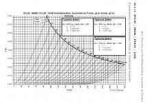
Triode Strapped Curves generated for 6BM8 Pentode
Hi All,
The 6BM8 contains a high mu line-level triode and medium power pentode (Pa ~7W) in one convenient glass envelope.
I made some rough triode curves for the pentode section. They can be found here:
Triode Strapped Curves for the 6BM8 Pentode – Greg's Stuff
Hope someone finds them useful.
Cheers,
Greg
Last edited:
Does anyone have any thoughts on how well the 6BM8 would work as a combined input and driver tube for a 300B SET amp?
The idea would be to use the high mu triode as the input and the pentode as the driver (pentode would be triode strapped as per my curves). I've been playing around with load lines and can get about 2% calculated H2 from the triode strapped pentode at 100V peak to peak output.
Any thoughts?
Cheers,
Greg
Yes, Two thoughts:
1.
2% 2nd harmonic distortion from the 6BM8 driver is in one phase.
2% 2nd harmonic distortion of a very hard driven 300B is in the other phase.
2% one phase - 2% the other phase = 0% harmonic distortion. Well, you get the idea.
That all is good and well when the amplifier drives an 8 Ohm load on the 8 Ohm tap.
But, there is no such thing as a single load line of a loudspeaker.
Depending on the frequency . . .
It will be resistive higher than 8 Ohms, it will be resistive less than 8 Ohms, it will be resistive at 8 Ohms.
It will be reactive at more than 8 Ohms, it will be reactive at less than 8 Ohms, and it will be reactive at 8 Ohms.
The various resistive loads will present load lines at different slopes.
The various reactive loads will all present elliptical load lines.
As a result, the 300B will be anything other than 2% harmonic distortion.
2.
Sounds like the basis of a good amplifier.
Try it, it will probably be much better than the pessimist's view above.
Happy building, and happy listening!
Ah yes, I had forgotten about the cancellation effect between the two devices. How useful it is!
Many thanks for the encouragement and advice, both here and in other threads.
I'll be posting a conceptual schematic in due course.
Cheers,
Greg
Many thanks for the encouragement and advice, both here and in other threads.
I'll be posting a conceptual schematic in due course.
Cheers,
Greg
6BM8 signal triode operating point
Hi All,
Another quick 6BM8 question I am hoping you can help with.
The 6BM8 datasheet here specifies the "average" bias voltage for the triode section as being -1.3V. Just wondering if this is right, as it seems close the the normal grid current cut-off? Seems to me it would be better off biased around -2V. However, if I can bias closer to -1V it would likely be more linear. Just not sure if grid current would become an issue.
https://frank.pocnet.net/sheets/164/6/6BM8.pdf
Appreciate your thoughts,
Greg
The 6BM8 datasheet here specifies the "average" bias voltage for the triode section as being -1.3V.
That's the manufacturer's test condition, not the 'average bias'. You can bias it wherever you like (I thought you liked distortion cancellation anyway?...)
Ah ok then, thanks for that. I thought it was the "typical operating conditions" or "typical design centre values" you see on a lot of other datasheets, which often seem to be a good starting point for the operating point.
And yes, I would bias at about -2v, 210Va and 3.4 mA myself....
And yes, I would bias at about -2v, 210Va and 3.4 mA myself....
Last edited:
Thanks Tom, I wish I had those a couple of weeks ago!
I have overlaid our curves for interest...quite different. My tests were done with a new Electro Harmonix 6BM8 and I tested 2 of them, both nearly identical. However, my test setup was less than optimal. Interesting to see the differences.
I have overlaid our curves for interest...quite different. My tests were done with a new Electro Harmonix 6BM8 and I tested 2 of them, both nearly identical. However, my test setup was less than optimal. Interesting to see the differences.
Attachments

Last edited:
Hi GregH2,
actually I think our plots are pretty close - maybe 5% to 10% difference in transcondutance? Valves used for plotting were (IIRC) either NOS Valvo (Philips) ECL82 or NOS Siemens PCL82.
If you do "sweep" plotting using a tracer, this might already explain the difference, since average Pd will be much lower than the quasi static plotting I do.
Regards, Tom
- Home
- Amplifiers
- Tubes / Valves
- Triode Strapped Curves for 6BM8 Pentode