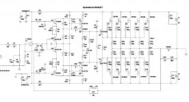
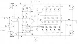
I have an amp design here, which evolved from non-symmetrical amps I already built in this thread.
So this is continuation, hopefully for the better.
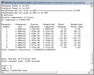
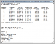
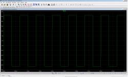
See the attached LTSpice sim file, and screenshots (for 1kHz and 10kHz).
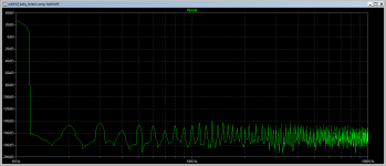
Everything seems to be working fine, except the clipping.
Looks kind of ugly.
Any help with improving clipping behavior (or anything else) in this amp would be appreciated.
Choice of transistors is determined by what I have (e.g. TTA/TTC, BD140, BC).
I simed it with different ones, to pretty much the same results. Also have higher voltage version with bigger fets,
but for this one I want to use IRF640/9640, as I have too many of them..
As it turns out, this thread evolved into "hands-on crash course in feedback stability", so keep reading if you want to
find out how to evaluate OLG, Bode plots, Phase Margin and Gain Margin.
For dummies.
Most recent schematic: post #69
So this is continuation, hopefully for the better.
See the attached LTSpice sim file, and screenshots (for 1kHz and 10kHz).
Everything seems to be working fine, except the clipping.
Looks kind of ugly.
Any help with improving clipping behavior (or anything else) in this amp would be appreciated.
Choice of transistors is determined by what I have (e.g. TTA/TTC, BD140, BC).
I simed it with different ones, to pretty much the same results. Also have higher voltage version with bigger fets,
but for this one I want to use IRF640/9640, as I have too many of them..
As it turns out, this thread evolved into "hands-on crash course in feedback stability", so keep reading if you want to
find out how to evaluate OLG, Bode plots, Phase Margin and Gain Margin.
For dummies.
Most recent schematic: post #69
Attachments
-
 wdrhld_baby_beast.comp.hexfet.10mar2021.jpg261.5 KB · Views: 671
 -
 thd_1.png25.9 KB · Views: 735
 -
 thd_10.png25.8 KB · Views: 647
 -
 fft_1.png25.4 KB · Views: 618
 -
 fft_10.png25 KB · Views: 618
 -
 sqr1.png37.7 KB · Views: 271
 -
 sqr2.png39.1 KB · Views: 266
 -
 clip1.png39.9 KB · Views: 341
 -
wdrhld_baby_beast.comp.hexfet.10mar2021.asc17.4 KB · Views: 103
Last edited:
Plots dont look too bad.
A little bit of HF on the clipping but I would suggest not enough to worry about.
Its not like its going to be clipping in normal use.
A little bit of HF on the clipping but I would suggest not enough to worry about.
Its not like its going to be clipping in normal use.
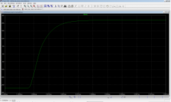
Wow, that's a lot of circuitry to tack onto the output of an op amp. Impressive performance. I'm curious about your loop-gain stability plots.
I think what is happening here is that when you clip the amp positive, current in Q1/Q5 goes to zero, and when you clip the amp negative, current in Q3/Q6 goes to zero. Are C6 and C7 there to help with this exact problem, or are they there for another reason? What happens at clipping if they are removed or increased in value?
I could be totally wrong about that. Emitter-couple pairs reestablish their current very quickly. It may simply be a matter of Q8 and Q10 saturating at clipping. A zener with Vbrkdn > 100V from the left side of R29 to the collector of Q10 may (cathode to collector) and another from left side of R28 to collector of Q8 (cathode to resistor) may cure it somewhat. In a real circuit, I would suspect quasi-saturation of Q9 and Q11, but I don't think quasi-saturation is in your transistor models. Also, it would be asymmetric, because the PNP would be worse.
Unrelated to your clipping problem: a thing that scares me a bit about the MOSFET outputs is that the gates charge faster than they discharge, the way you are driving them. That will increase their effective bias with high frequency signals. Have you tried putting a decent sized capacitor across R24, say 1 to 10 uF? This won't show up as extra distortion, in fact distortion may get worse if you add the cap. It shows up as very hot output transistors when doing THD at full power and high frequency.
Also Nigel is right (and also Wright). It's not really a big deal if you don't often clip the amp.
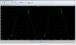
Thanks Russell - the Zeners helped perfectly.
Clipping looks very nice, and they don't seem to have any side effects.
In the sim I used 82V Zeners, and they clip nicely at 40V, which is about right.
Capacitor added in parallel with C12, doesn't seem to affect anything in the sim (Thd at higher frequencies is minimally lower), so it wouldn't hurt to keep it, if it's gonna help with effective bias in the actual build.
C6/C7 have nothing to do with clipping. They were added to the original Wiederhold design, by Russian designer Sukhov, and their function was to linearize conversion of op-amp output voltage to the current of the collector of Q1. They affect overall stability of the amp.
The evolution of this design was described to some degree in the thread linked in post #1. For some strange reason, this particular topology, starting with Wiederhold, Lomakin and Parshin, Ageev and Sukhov, has been very popular in Russia.
OLG plot added.
Attachments


Last edited:
Well, I guess that can work too. My intent was not for the Schottky transistors to have reverse breakdown, but to have a forward voltage lower than the forward voltage of the BC diodes of Q8/Q10. Basically, these are Baker clamps.
What happens if the Zener breakdown is >90V? Does it still help?
What happens if the Zener breakdown is >90V? Does it still help?
>What happens if the Zener breakdown is >90V? Does it still help?
No, doesn't have any effect on clipping. 100V is definitely too high, and then next Zener voltage in LTSpice lib was 82V. With 82V it's clipping just 1V or 2V below 'natural' clip.
Will try to adjust/select the Zener voltage in the actual build. Maybe 84V - 85V will be optimal.
Correct spice sim file with Zeners is attached here.
Attachments
Last edited:
You are still missing my point. And I understand why. I said zener, when I meant to say Schottky. 
The Schottky forward bias is a lot lower than the CB diode of the transistor, and will keep the transistor out of hard saturation. Try it again with a 100V Schottky (not Zener) this time. Sorry to cause confusion. Lack of sleep.
The Schottky forward bias is a lot lower than the CB diode of the transistor, and will keep the transistor out of hard saturation. Try it again with a 100V Schottky (not Zener) this time. Sorry to cause confusion. Lack of sleep.
Last edited:
Tried Schottky diodes (100V & 150V).
Either they don't have any effect, or actually cause slightly more oscillations, not just on corners, but on the whole slopes...
Amazing how the misunderstanding Zener vs. Schottky actually worked 🙂
I don't see anything wrong with Zeners, as long as they work..
Either they don't have any effect, or actually cause slightly more oscillations, not just on corners, but on the whole slopes...
Amazing how the misunderstanding Zener vs. Schottky actually worked 🙂
I don't see anything wrong with Zeners, as long as they work..
Last edited:
Hi Minek,
I reduced the counts part, changed to the Toshiba bipolars and IRFP240 series at the output. With 58mA quiescent it gives you VERY low 1KHz distortion with relative simplicity.
I dropped the shunt fb cap. If you use the 1056 IC it should control the offset very well.
This is a very good way to build a power amp at low cost. Thank you for showing it to us!
Hugh
Attachments
Hugh,
This is a very nice cross of Alexander amp and symmetrical Wiederhold 🙂
No drivers?
I tried something similar like this, but driven from op-amp output, in this post:
https://www.diyaudio.com/forums/solid-state/357369-unusual-amp-1987-a-11.html#post6330382
Your amp here might be different, most likely for the better.
Hi Minek,
Yes, it's a clean circuit, combination of IC rail regulation and cascode is elegant, but there are issues.......
20KHz THD is a little higher than I'd like, and H3 is close to H2.
The other issues is clip; it runs out at 43.5Vpk with a full 50V rail, this is not good efficiency and there seems to be bad ringing coming off clip which I don't seem to be able to reduce.
I've attached the .asc
Hugh
Attachments
Hugh, I see two ways to fix clipping:
1) 2 GREEN LEDs across the op-amp. Usually this will worsen the Thd, but in this case Thd was not extremely low to start with, so I see no impact.
I my amp from the post #1, Thd was getting worse, so I opted not use this solution; here it's OK.
2) clamp zeners (see sim) with appropriate voltage (~90V) depending on rails. Voltage should be adjusted in a way that will cause civilized clipping 1V before 'natural' clip (more inefficiency).
Sim attached (didn't have your models...).
Attachments
I like it. Works well....... good thinking, Minek, would not have used LEDs here!!
I noticed you removed the three resistors between the rail transistors, and the two caps. Good idea! Not needed. You could also remove that 100R load resistor on the opamp output. Direct connect the opamp to ground. This hugely improves 20KHz.
I think this is pretty good. The profile is not exactly what I like, but it's very good, THD is low enough and it has low parts count.
I particularly like the offset control, loop gain and low noise that the IC brings to this topology.
I think this could be built and tested now, what do you think?
Hugh
Last edited:
Hugh, I think this was very good idea to drive cascode from op-amp rails.
I modified my original amp from post #1, but not in such extreme way like yours, as far as parts count goes 🙂
All the numbers (Thd, FFT profile) and behavior is the same as before (post #1), but it's simpler, more stable, and slightly faster.
With this kind of symmetrical amps, there is always an issue at the junction point of the upper and lower half - they meet at op-amp output, but it's not easy to actually achieve true symmetry in there..
This approach eliminates the problem.
>I particularly like the offset control, loop gain and low noise that the IC brings to this topology.
Right. All my recent amps use op-amps. You get all these things you mention above for the cost of the TL072,
plus you get perfectly matched JFET input, pretty much for free 🙂
Attachments
Last edited:
Minek,
You have used a Hawksford cascode on each VAS but it has used a lot of parts (two more transistors, six resistors and two LEDs). This adds to parts count and costs a bit of headroom.
I would be surprised to see that this cascode improves the performance, but I may be wrong. We are driving common base transistors after all. What are your thoughts?
Can you identify how the numbers improve with this cascode?
The other issue is the bias generator. With the bipolar Vbe multiplier you will have dropping quiescent with temperature even with R16; it might be better to use a mosfet Vgs generator; it will give you accurate quiescent control for a mosfet output stage.
BTW, you can drop the fb shunt cap. The IC is so good that it will keep offset at the output <1mV.
Cheers,
Hugh
Hugh, I think this was very good idea to drive cascode from op-amp rails.
I modified my original amp from post #1, but not in such extreme way like yours, as far as parts count goes 🙂
Every transistor in your VAS is a cascode. 1st is a Hawksford, then a folded, and then a telescopic. It kind of makes me feel warm and fuzzy inside. Yes, this will have much better stability, because you've thrown out a gain stage, but not the gain. (I have to be honest, though. You could probably replace the Hawksford cascodes with a wire to the 47 ohm resistors, and the amp's behavior would not be noticeably different.)
- Home
- Amplifiers
- Solid State
- Symmetrical amp clipping behavior - help needed