Problem with Tian probe is the transfer equation that you added, How do you know if this equation is correct?
Most people as LKA, use simpler way explained here, LTspice Stability of Op Amp Circuits - YouTube which unlike Tian can be used on Tina. Another method described by Bob Cordell can be used if the impedance of the feedback network is much higher than the output impedance, which is not precise for CFA.
A pole and zero are representing points on Nyquist polar graph for low pass and high pass cut frequencies. Your dominant pole for example is about 20hz.
>Problem with Tian probe is the transfer equation that you added, How do you know if this equation is correct?
I don't know, but I can see that Damir and Russell are using it (with great success), and they say it's good. Who am I to doubt it ? Have to trust someone...
It's a pity it's not Tina compatible, I forgot you are using Tina only...
Will check out the other methods - hopefully plots generated will be, as you say, simpler and more obvious.
Kenneth Kundert walked me through the Tian method in a day-long presentation of the stability analysis tools available in Spectre (A SPICE tool for analyzing integrated circuits). He wrote the Tian analysis routine in Spectre. It is similar to the Middlebrook method, but more accurate with respect to feedforward loading. I am satisfied that it is accurate, as are the people who design every integrated circuit that includes an amplifier.
If you are doing a CFA, I think the Tian method is the only way.
The Tian method is actually included in the example circuits provided by LTspice with the download.
If you are doing a CFA, I think the Tian method is the only way.
The Tian method is actually included in the example circuits provided by LTspice with the download.
...
If you are doing a CFA, I think the Tian method is the only way.
The Tian method is actually included in the example circuits provided by LTspice with the download.
I use Tian in all CFA simulations.🙂
Kenneth Kundert walked me through the Tian method in a day-long presentation of the stability analysis tools available in Spectre (A SPICE tool for analyzing integrated circuits). He wrote the Tian analysis routine in Spectre. It is similar to the Middlebrook method, but more accurate with respect to feedforward loading. I am satisfied that it is accurate, as are the people who design every integrated circuit that includes an amplifier.
If you are doing a CFA, I think the Tian method is the only way.
The Tian method is actually included in the example circuits provided by LTspice with the download.
For those interested in some background on the Tian method:
https://kenkundert.com/docs/cd2001-01.pdf
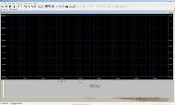
Not sure if this plot makes sense.
GM seems to be minimal, while PM huge..
Different than Damir's last plot.
Judging from Damir's plot from post #43 (with C10=7pF) PM already improved to 18 degrees.
The latest sim (post #40) has C10=3pF and C8/C9 also lower, so I would expect further improvement..
Still experimenting..
GM seems to be minimal, while PM huge..
Different than Damir's last plot.
Judging from Damir's plot from post #43 (with C10=7pF) PM already improved to 18 degrees.
The latest sim (post #40) has C10=3pF and C8/C9 also lower, so I would expect further improvement..
Still experimenting..
Attachments

Last edited:
I realy don't know what that plot represent, this is not correct LG plot. Why do you not do the plot like in my post #43?
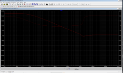
That's what I get if I try method from post #43.
Sim attached how I did it.
Sim attached how I did it.
Attachments
Last edited:
What are the acceptable values for GM and PM, for an amp to be considered stable and build-able?
Looks like PM in perfect world should be > 45 degrees, right?
Looks like PM in perfect world should be > 45 degrees, right?
Last edited:
What are the acceptable values for GM and PM, for an amp to be considered stable and build-able?
Looks like PM in perfect world should be > 45 degrees, right?
My goal is to get PM more than 60 degree and GM more than 10 dB.
Mostly I've got PM between 70 and 90 degree and GM between 20 and 30 DB, and that with CFA.
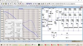
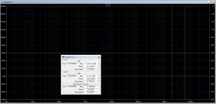
OK, this is the latest plot, that at least looks like Damir's plots,
so I guess it's more or less OK.
PM: 26 degrees, GM: 13dB
Far from OK, but better than yesterday...
The thing is I'm getting different plots from Tian method, and from simplified method.
This one here is from simplified method. Plot from post #48 is from Tian.
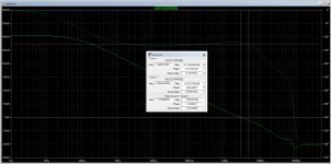
Update: attaching Tian plot here (2nd atachement).
They look different, and of course produce different PM and GM.
so I guess it's more or less OK.
PM: 26 degrees, GM: 13dB
Far from OK, but better than yesterday...
The thing is I'm getting different plots from Tian method, and from simplified method.
This one here is from simplified method. Plot from post #48 is from Tian.
Update: attaching Tian plot here (2nd atachement).
They look different, and of course produce different PM and GM.
Attachments
Last edited:
What are the acceptable values for GM and PM, for an amp to be considered stable and build-able?
Looks like PM in perfect world should be > 45 degrees, right?
For full transistor implementations, PM has to be > 60 degrees. Loads and speakers can be weird and amp testers like to hook up dangerous loads, so I shoot for > 65 deg.
GM, I normally shoot for > 10 dB. My lastest design shows 8 dB GM, and I reckon I'm happy with it.
I doubt U1 would be happy driving a 10R load R6 connecting to ground, 1k simulates better. C10 could then be increased to suit the desired stability margins.
With 1k op-amp load, 100pF across that 1k resistor, and C10=7pF
PM is 36, GM 26. Big improvement.
Adding 10pF across the op-amp makes PM=25 and GM=60
But of course Thd and FFT look slightly worse..
PM is 36, GM 26. Big improvement.
Adding 10pF across the op-amp makes PM=25 and GM=60
But of course Thd and FFT look slightly worse..
Last edited:
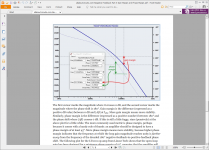
There is direct correspondence between PM and overshoot.
http://www2.units.it/carrato/didatt/E_web/doc/application_notes/overshoot_and_phase_margin.pdf
https://training.ti.com/system/files/docs/1334 Stability 4 - slides.pdf
http://www2.units.it/carrato/didatt/E_web/doc/application_notes/overshoot_and_phase_margin.pdf
https://training.ti.com/system/files/docs/1334 Stability 4 - slides.pdf
Last edited:
I'm not sure I am on the right track here. Using dadod's Tian model from post 22 I am getting a phase margin of around 60 degrees - the same number you have for gain margin. I have this around 17dB.
In addition to the first mentioned change with 100pF across R6 at 1k Ohm, I omitted the 10pF across U1 and made C10=39pF with 1k8 Ohm in series to form a step network.
In addition to the first mentioned change with 100pF across R6 at 1k Ohm, I omitted the 10pF across U1 and made C10=39pF with 1k8 Ohm in series to form a step network.
Tian probe was giving me strange results.
Only simplified method yielded plots/numbers comparable with Damir's...
Only simplified method yielded plots/numbers comparable with Damir's...
This 1k load on op-amp, while making amp more stable, increases Thd and makes FFT not-that-flat-anymore, and instead of staying below 150dB, now it's spiking to 120dB.
That makes the double cascode most likely unnecessary, as Russell predicted.
Will keep simulating this, to see if there is some kind of acceptable compromise...
I've seen many amps driven like this with lower load, perhaps not as extreme as 10 Ohm, but maybe 33 or 47 will do..
That makes the double cascode most likely unnecessary, as Russell predicted.
Will keep simulating this, to see if there is some kind of acceptable compromise...
I've seen many amps driven like this with lower load, perhaps not as extreme as 10 Ohm, but maybe 33 or 47 will do..
Last edited:
- Home
- Amplifiers
- Solid State
- Symmetrical amp clipping behavior - help needed