Right. All my recent amps use op-amps. You get all these things you mention above for the cost of the TL072,
plus you get perfectly matched JFET input, pretty much for free 🙂
Not very stable, just 11 degree of PM and 2 dB of GM🙁 but very low distortion.
Attachments
>Not very stable, just 11 degree of PM and 2 dB of GM🙁 but very low distortion.
Damir, any suggestions how to improve it?
Damir, any suggestions how to improve it?
Regarding the two cascodes vs. one cascode - according to the sim, 2 cascodes make it marginally better - flatter fft with bottom at 180dB vs 170dB, and slightly better Thd across the bandwidth. I'm sure this won't make any difference to the sound, and no one will be able to tell the difference...
But - since when building amplifiers is a rational thing to do ? 🙂
I've already built 4 amps with single cascode like this, and can't tell them from quasi amps from the 80s. Must be my tin ears..
It doesn't make sense to built another one like this, so I'm looking for some 'differentiating' factors 🙂 And since this 2nd cascode improves things A LITTLE, at least on paper, then why not?
>Not very stable, just 11 degree of PM and 2 dB of GM🙁 but very low distortion.
Damir, any suggestions how to improve it?
You have to compensate it better.😉
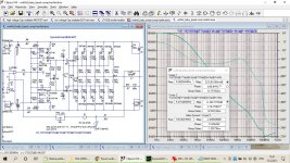
I have simed versions with 1 cascode vs 2 cascodes (Hawksford) (attached).
FFT profile looks definitely better for 2 cascodes. Flatter, more linear, lower levels in general.
Thd also much better for 2 cascodes.
E.g. for 1kHz: 0.000001% vs 0.000721%
Perhaps the latter number can be still improved a little, but it will not get anywhere close to 0.000001% with single cascode.
Will this difference be audible - no.
Will these numbers actually translate into a real build? Most likely also no.
But that's not a reason not to do it. Otherwise why even bother?
I simed dozens of variations of single cascode amps (symmetrical and not) in this thread:
Unusual amp from 1987
and I think I already squeezed all I could from this topology..
Attachments
Last edited:
> it might be better to use a mosfet Vgs generator; it will give you accurate quiescent control for a mosfet output stage.
I seldom see people using mosfet for thermal tracking here...
Usually there is a Red LED in place of my R16..
Is there any suitable small mosfet you can suggest? Or TO-126 ?
I've seen someone using IRF610 in this role, but that's TO-220.
All plastic, smaller device would be better.
I seldom see people using mosfet for thermal tracking here...
Usually there is a Red LED in place of my R16..
Is there any suitable small mosfet you can suggest? Or TO-126 ?
I've seen someone using IRF610 in this role, but that's TO-220.
All plastic, smaller device would be better.
Why you don't show the Loop Gain plot?
See this post:
https://www.diyaudio.com/forums/sol...l-amp-clipping-behavior-help.html#post6567191
this was for previous version from post #1
Last edited:
I did not really look closely at the first loop gain plot you showed. Your original loop gain plot agrees with Damir: you have about 11 or 12 degrees of PM. That's life on the edge, for sure. However, that is loop gain/phase from the original circuit, before you removed Q5 and Q6 at the input.
The main loop compensation is in the LT1056, compensated for unity gain of 5.5 MHz. That sets the dominant pole of your amp. The next pole that you add it needs to be no lower than 2 * 5.5 MHz / 28 = 400 kHz. (28 is the CL gain of your amp.) The higher you can make that pole the better.
The first pole is set by the LT1056. C8 and C9 are setting your second pole. You probably need to lower those values to increase your overall PM. I could be wrong.
Then you can adjust C10 to get a little more PM, maybe 5 degrees. Any more than about 5 pF is probably too much. Usually this can only cancel the input pole of the amplifier. I bet C10 doesn't help you much in this amp.
Thanks Russel.
> I bet C10 doesn't help you much in this amp.
Hugh was suggesting removing it completely...
I run OLG plot for a new version (driven from op-amp rails) - looks exactly the same as the 1st one..
High values of C8/C9 are because of the square waves overshooting... These values can go lower, but square waves will look
'less perfect' 🙂
Last edited:
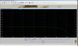
According to that gain-phase plot, your amplifier is not stable. That plot doesn't make any sense, because it is not consistent with your closed-loop gain/phase. Maybe you can use the Tian loop-break method that Damir is using to plot loop gain/phase, and it will make more sense.
Yeah, I'm in a process of researching/reading about these Bode plots..
I know about Tian method, but have never done it myself..
I couldn't match my plots with Damir's..
I know about Tian method, but have never done it myself..
I couldn't match my plots with Damir's..
Last edited:
Tian loop-break method for Bode stability analysis
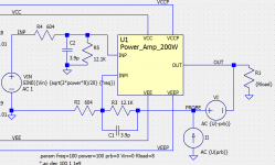
In Damir's testbench you can see the Tian probe between the feedback resistor and the output. It's a voltage source in series and a current source in shunt. You need to add those to your schematic. They don't affect other simulations.
1)Set the voltage source to DC=0, AC={U(-prb)}
Set the current source DC=0, AC={U{prb)}
2) Add these lines to your spice directives:
.param prb=0
.step param prb list -1 1
3) Add this to your plot.defs file in <USERNAME>\Documents\LTspiceXVII:
.func stb() -1/(1-1/(2*(I(VI)@1*V(PROBE)@2-V(PROBE)@1*I(VI)@2)+V(PROBE)@1+I(VI)@2))
4) Make sure all your other AC sources (input source for instance) are set to zero. Only the Tian sources are allowed to have AC.
5) Then, run an AC analysis. In the plot window, right click and choose "Add Traces". In the "Expressions to add:" at the bottom, type stb()
Good luck.
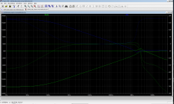
I like to run stability analysis at several points in the signal swing. Here are some details on how I do that.
Tian Stability Plot at multiple points across the Output Swing
In Damir's testbench you can see the Tian probe between the feedback resistor and the output. It's a voltage source in series and a current source in shunt. You need to add those to your schematic. They don't affect other simulations.
1)Set the voltage source to DC=0, AC={U(-prb)}
Set the current source DC=0, AC={U{prb)}
2) Add these lines to your spice directives:
.param prb=0
.step param prb list -1 1
3) Add this to your plot.defs file in <USERNAME>\Documents\LTspiceXVII:
.func stb() -1/(1-1/(2*(I(VI)@1*V(PROBE)@2-V(PROBE)@1*I(VI)@2)+V(PROBE)@1+I(VI)@2))
4) Make sure all your other AC sources (input source for instance) are set to zero. Only the Tian sources are allowed to have AC.
5) Then, run an AC analysis. In the plot window, right click and choose "Add Traces". In the "Expressions to add:" at the bottom, type stb()
Good luck.
I like to run stability analysis at several points in the signal swing. Here are some details on how I do that.
Tian Stability Plot at multiple points across the Output Swing
Tian Probe
Here's a picture of my Tian probe, to to help the formula in step 3 make sense. The Tian method runs two AC sims, and does some math using the data from both runs.
You will notice that Damir has his Tian probe backwards compared to mine. That's the beauty of Tian. It does not matter. Tian is especially useful for breaking loops in current FB amplifiers. Tian cleanly breaks the loop without changing how the feedback and input loading affect the output.
Attachments
Thanks Russell! Your help is very appreciated!
Update: nice post back from 2015. Came handy now 🙂
Update: nice post back from 2015. Came handy now 🙂
Last edited:
You have an important element R6 10 ohm grounding the opamp output, which determines the overall transfer function. You can add pole/zero at this point very easily.
You can try out other opamps who's open loop BW is about 20khz, as AD825,AD826.
You can try out other opamps who's open loop BW is about 20khz, as AD825,AD826.
Last edited:
Hi Hayk! Where have you been recently?
Tian probes, poles and zeroes, I guess I ought to go back to school, and pay more attention this time 🙂
Tian probes, poles and zeroes, I guess I ought to go back to school, and pay more attention this time 🙂
Last edited:
- Home
- Amplifiers
- Solid State
- Symmetrical amp clipping behavior - help needed