KENWOOD L-07 CII preamp

It's my first thread here.

I have a Kenwood L-07 CII with a problem on the right input phono MC stage ( noisy with cracking... ).
But without diagram impossible to repair.
And also impossible to find service manual, schematic, information about, ...

Please I need your help !
Raymond

My preamp :
An externally hosted image should be here but it was not working when we last tested it.

buzzing input...

Dear builders
Uhm...
My preamp has an annoying buzz. it's not very loud (music overshadows it) but constantly there.
It is not being attenuated (level is constant).
I disappears when I unplug the only input, a USB-dac.
swapping the dac doesn't change, I use a halide DAC HD (usb-powered) or a furutech ADL gt-40, more a preamp than just a dac)

Am I describing a ground-loop?

Many thanks!

Rookie question about thermal pastes

Rookie question about thermal pastes / Rectifier Q

Hi all,

I've had to unbolt this heatsink to move my PCB so I can replace the speaker relay on the board. About to put it back together and thought maybe this paste is insulating the rectifier from the chassis ?

I've looked up the datasheet and it states 'Case to Terminal Isolation Voltage 1500V' which I think means it doesn't need insulating. However I'd rather double check with you guys before blowing my amp up 😀

Thanks,
Rob.

Attachments

  • 20210807_150030_resized.jpg
    20210807_150030_resized.jpg
    861.2 KB · Views: 207
  • 20210807_150038_resized.jpg
    20210807_150038_resized.jpg
    385 KB · Views: 206

FS: Ian Canada streamer project

Hi Guys

Because I can get a good deal on a commercial audiostreamer I will no longer pursue this project. The deal concists of the following parts;
1A FIFOPI Q2 Reclock Module FIFO PCM 32bit 768kHz DSD1024 DoP with Accusilicon presicion clocks
23A SHILDPI
20A TRANSPORTPI Digital Interface SPDIF Low Jitter
5A ES9028Q2M DacHAT
6A I/V Standard output board including OPA1612 and OPA1622 op-amps
3A ESS SABRE 90X8 controller with display
8A ESSC Controller Extension Kit
I'm asking $450 shipped.

Attachments

  • Ian Canada Boards.jpg
    Ian Canada Boards.jpg
    565.2 KB · Views: 1,066

VTR-Project:Umatic DUB to Y/C conversion

Hi !

Since I have a couple of Umatic-VTRs around, I wanted to integrate them in my Y/C-video setup.

INTRO:
The S-Video Y/C-format uses Y & C signals, where the C-part is encoded @ 4.43 MHz (PAL)

To those who don't know - the 2 Umatic - studio VTRs came with DUB-connectors. That was a 7-pin port, that provides

1. separate Y-line (the luminance-signal), which is fully S-Video Y compatible (4.43 MHz)

2. a "color-under" coded C-line, which,depending on the tape-format works at different frequencies (<-and this is the trouble-maker - it's running at 688 - 924 kHz)

The Umatics provided these ports for better-quality machine to machine dubs, in order to circumvent the composite en/de-coding circuitary, which generates quite a loss in vid. quality.
The signals present at those dub-ports are basically as they get recorded on tape..


So I made a bit of investigation :

* According to my handy TV-technician-Cookbook, *all* home VTR are using (recording with) the color-under technique.
A VHS (PAL) for instance 626.9kHz, a Betamax 685.5 kHz & 689.4 kHz

* All VHS & Betamax VTRs are treating it's signal in the following manner:
1. they split it up into the Y & C-components - using BP/notch-filters
2. they modulate the C-component down to 626.9kHz

So all I need to do is use the same technique that a VHS-VTR uses to de/-modulate the FBAS 4.43 into it's internal subcarrier-format & vice versa - then I'm done right ?


* Reading further on, I found out, that the C-conversion is done rather quite simple - by applying some average FM-voodoo.

1. the C-signal gets filtered trough a BP-filter, to ensure we have a clean 4.43 MHz *modulated* signal present.
2. then the signal gets converted DOWN by simply mixing it with
a) a 4.434MHz color-carrier
b) an Oscillator, which is running exactly with a difference of 626.9kHz above the C-frequency (5.061 MHz for instance)
- which leads to a new subcarrier @ 626.9kHz !

* This voodoo is reversible - by simply applying a 5.061 MHz oscillator to the 626.9kHz color-under-coded (modulated) signal !

(- and maybe cleaning it up a bit with a filter - though in theory it's ready to use !)

CONCLUSIONS:

- since I'll start to build this converter firstly for Y/C (S-Video)-ports, I don't need to worry about filtering, since the C-signal is already present in a "clean format".

- So the only thing I'd need to build is a precise 5.0xx MHz oscillator...

QUESTIONS:
Am I correct about my conversion theory ?

Anyone made a Y/C-to composite AND composite to Y/C-converter - or something alike ?

Anyone out there using umatics, wanting to do (or have) the same thing ?

Anyone made an *precise* 5.00xxx MHz (and I mean precise at the "x"-ses 🙂) oscillator ?

Should I go the PLL-route - or fiddle around with a quartz ?

How about building a low(er)-frequency oscillator & using clock-multipliers ?


Thanks for any hints in advance & happy holydays to everyone !

In the meantime, I'll play around a little bit with my oscilloscope and some transistor HF-oscillators..

My F4 build (questions, bragging, and other thoughts)

Hi there

Just as mighty ZM suggested, I would like to start a thread about my F4-build. This is my second power-amplifier after ACA, so many details are really obscure to me.

The build-process and everything that comes with it is a great, no, a fantastic experience, thanks to all here @ diyaudio.

Although it is nearing completion, I very well may have one or the other question.

I will post those, as well as presentations of the process, as follow-up posts right here.
I‘m confident they will be answered [emoji4]

Before I begin to shamelessly exploit your knowledge [emoji83], let me say thank you so much for your patience, sense of humour, sharing expertise, and above all of course, thank you very very much Mr. Pass!

Noise in my stereo tda2003 amp

I got a loud noise in amp tda2003 amp.

When I connect the amp to a 12volt battery the noise in my speaker ca be barely heard.But when I connect it to an unregulated power supply (15volt transformer,rectifier,4700uF capacitor) I get a loud noise.

I did some experimenting -added an LM78.. regulator.At 18volts I get the noise.At 15volts the same.But at 12 volts the noise is gone.Maybe its volume is reduced enough not to be detectable by ear.

I tried to move cables around within the enclosure-power cables away for audio cables but nothing happens. I even took the transformer entirely out of the metal box .The result is that the noise get even louder.

I suspect a ground loop,a cold solder connection or even a bad component.I have no idea how to pinpoint the problem.Maybe its the tdas themselves.

What else can I try?

Here are the schematics and some pictures of the amp within the metal case.
As DIY as it gets! ????????????????: TDA2003 stereo amplifier with tone control 20 watts (10+10)

tda1.jpg


tda2.jpg


tda3.jpg


tda4.jpg

In Search Of Cambridge Soundworks P1000 Sub Control Module

I know this is a long shot, but I've got a beautiful CSW P1000 sub in absolutely mint condition, but no control module for it. Does anyone have one of those sitting in a basement somewhere? I'd be happy to buy it off you. It's making me sad seeing that gorgeous bassy beast sitting there idle just because it's missing this component.

Earthquake tnt td5x

Hi all
This 5 channel amp came with two channels not working. It using TDA8920BJ IC each for two channels. I changed the IC now all 4 not working. Audio signals reaching the ic and there is oscillations on pin 1. This board totally have 3 494 ic. Anybody have any suggestions will be highly appreciated. Is there a way to force channels to play?

Attachments

  • 20210806_100503.jpg
    20210806_100503.jpg
    1,004 KB · Views: 100

Motorola SH12E speaker impedance

restoring a simple Motorola SH12E hifi record player, and a few holes got in the speaker cones while cleaning the cadmium oxide off the frame with a brass brush dremel tip, so i figured i might as well replace them wholesale.

something doesn't line up for me, however, when looking at the specs for the output section. i'm hoping the attached pdf of the schematic works, if not, this one is easily google-able.

what i am seeing is each 6BQ5 in triode mode, class A, which should mean it wants to see 3500 ohms of load impedance. this schematic shows the impedance ratio of the OPT to be 500:1, so the speaker impedance should be 7 ohms; the standard 8 ohms being even easier of a load to drive.

each speaker measures about 7.3 ohms of DC resistance, indicating they are 8 ohm speakers. but they are wired with two in parallel for each block (one 4", one 6"), which should mean that the total speaker impedance is 4 ohms... right? seems like this would be way too hard of a load for the single 6BQ5.

does the big 5uF cap between the two speakers affect the impedance? that's my best guess, i come from a guitar background and have never seen a cap between different sized speakers like that before.

Philmore # TS60 6.0" Square Flanged Speaker, 8 Ohm 10.0 Watts – MarVac Electronics

thinking this sucker, and its 4" cousin, would do the trick. thoughts?

also actively seeking literature and resources on the belt drives for these units, including how to recognize different styles, and how to maintain them.

Attachments

Application for DDRC-24?

I want to implement something akin to what Magnepan has suggested in the following:

Magnepan

No place for a center channel speaker?

The photo below is of a demonstration in a hotel during a Consumer Electronic Show. The MC1s immediately flanking the on-wall video monitor provide a dual center channel array which can outperform a single center channel speaker.
A pair of our on-wall speakers achieves a center channel image in the same manner as a stereo system achieves a center image. By angling the speakers approximately 30 degrees to the wall, the center channel speaker on the left of the video monitor is on-axis with the viewer off to the right--- and consequently is louder than the center channel speaker on the right of the monitor (which is closer to the viewer). This "pulls" the audio image to the left and keeps the dialog centered on the screen better than point source speakers. It also raises the center channel image to the same height as the screen....

See attached image from the Magnepan site will give you the idea.


I have 4 DML speaker panels to use in the following configuration:

Left - Center left - TV - Center right - Right​

The LG OLED TV only uses a single digital source (an Apple TV).
No subs & no surround needed in this application.
I don't want an AV receiver with lots of functionality I'll never use.
AV separates seem overkill.

The first of the attached images shows:

1. An image from the DDRC-24 User Manual showing how it can support left right and 2 sub woofers.

2. My markup of the above wondering if a DDRC-24 could support what I'd like to do.​

Can this work?

I think I could use the DDRC-24's DSP to make a "synthetic" center channel output that would work fine for my application. The DDRC-24's DSP probably has a number of ways to do this.

I would plan to use a DDRC-24 and a pair of ICEpower 50ASX2SE stereo amps (2X50W).

I've used similar amps with DMLs in the past. Great combination.

I don't need world class center channel. I just want to hear the dialog and believe that the DMLs will excel in such a configuration.

So, would this work?
Thoughts and guidance appreciated.

Attachments

  • Screen Shot 2021-08-08 at 7.36.25 PM.png
    Screen Shot 2021-08-08 at 7.36.25 PM.png
    86.9 KB · Views: 179
  • Screen Shot 2021-08-08 at 6.14.33 PM.png
    Screen Shot 2021-08-08 at 6.14.33 PM.png
    233.6 KB · Views: 183

Crown XLI 800 airflow question mounted upright

Hi I want to mount my new Crow XLI 800 amp next to my chair on wall in a corner of my lounge. It is for powering my subwoofers.

I want the front face of the amp facing the ceiling and I will build a box around it to do this.

Is this ok for amp as it was never designed to go face up? How much space for airflow should I leave around it in the box?
Tim

Dayton OPA150 AMP issues, only turns on when I physically heat it up w/ a dryer!

Dayton APA150 AMP issues, only turns on when I physically heat it up w/ a dryer!

Alright so the stereo amp I have been using to power a pair of bookshelf speakers connected to my PC have recently starting shutting down on me. I can get it kicked into ON mode if I heat it up with a dryer, however, if the room gets too cold, I again have to take out the dryer.

I made a very lengthy post over at the EEVblog asking for help and even replaced what we thought might be bad diode to no avail, same problem persists. I will leave a link so you may view my post and pictures. OPA150 Stereo AMP issues, only turns on when I physically heat it up w/ a dryer! - Page 1

I guess what I'm now trying to do is pretty much Frankenstein this thing and that's where I could use some help. Unless someone can review the above post and knows a way around to keeping the amp on constantly, that'd be awesome.

I have been looking at Amp boards to replace the current boards that are in the Dayton amp, basically just use the case (which is nice), connections (RCA, Speaker etc).
I've heard great good deal about some Class D amps based on TPA3255 such as Amplifier Board - AIYIMA B2D2205 - TPA3255 | 4 Channel 315W Power Ampl It's two more channels than I need but I suppose has expandability in future?
That board requires a DC24-48V, I thought about getting this Amplifier Board - AIYIMA B2D1877 | Schottky Rectifier Filter Power Boa and just using the 28.4V toroidal transformer that's already in the Dayton and that takes care of my power supply.


But this is bit going over what I really want to spend on a Frankenstein build. Then I came to thinking that the rectifier 28vAC to 28vDC part of the Dayton amp works, why can't I just wack off the rest of the amp and keep just the rectifier part that gives out 28V DC and hook up a 2 channel board to it.

Do any of the electrical folks know where I would tap this DC power? The rectifier setup is not that complicated, Its AC-0-AC into a Rectron RS 802 single phase bridge rectifier rated at 100V, 8Amps and then into a pair of 5000uf caps for smoothing I guess usually from there it would go into a voltage regulator but that's where I got lost. Do these boards like the one I linked have their own voltage regulators? I'm pretty sure I can just tap the power somewhere after the caps.

given I have the power supply issue taken care of, is there any other 2-Channel boards you guys recommend?

Or should I just get Amplifier - AIYIMA A07 - TPA3255 | 2.0 Channel | 300Wx2 | HiFi and call it a day? Are these good?

I'm sorry my post is all over the place but I'm just tired of keep using the hair dryer to keep my amp running and I don't feel like spending $180 for another one. I've look at AudioSource amps as well but I dont like their form factor, I have no space on my desk for it.

Thanks for reading my nonsensical post, let me know if you guys have questions or ideas.

What about TPA3255 2x260W 2Ch Class D Audio Amplifier|Amplifier| - AliExpress paired with https://www.aliexpress.com/item/32880495843.html?spm=a2g0s.9042311.0.0.129c4c4d4HAXzH which I can connect to the transformer already in the amp. Would this work?
Any idea on how I can control volume on the TPA3255 Amp? I'm using a TOPPING D10 DAC and would like a physical knob and not rely on my computer for volume.

Attachments

  • Front (CUstom).JPG
    Front (CUstom).JPG
    487.2 KB · Views: 284
  • LeftChannel (CUstom).JPG
    LeftChannel (CUstom).JPG
    588.2 KB · Views: 325
  • RightChannel (CUstom).JPG
    RightChannel (CUstom).JPG
    599 KB · Views: 277
  • PowerBoard1 (CUstom).JPG
    PowerBoard1 (CUstom).JPG
    661.7 KB · Views: 266
  • PowerBoard2 (CUstom).JPG
    PowerBoard2 (CUstom).JPG
    545.3 KB · Views: 307

Woodworking question; Glue and Stain

I came across some 3/4 furniture grade plywood, which I need to extend the length of 4 pieces, by butt-joint glueing a 3/4" square hardwood stick to the edges at either end. I have a large bottle of Elmer's yellow -

I'm planning on staining and finishing the top surface and I know some glue will squeeze out of the joint. Obviously I dont want that to interfere with the stain. Do I just wipe off the excess? With a water soaked rag? Do I just let it dry and no problem after sanding? Scrape it off partially dried?

Stain before gluing?

How should I handle this? BTW, I've got one shot to get it right - and not have it look like crap for all my effort when done. Thanks!

Frequency Roll off changed - ideas

Hello everyone,

Yet another fault in my system.....yawn.

I have a 211 power amp that has become duller/rolled off and when my brother came to visit now covid restrictions are lifted he commented how recessed and dull it sounded. He is into his AV and has a microphone connected to REW software and we compared 3 amplifier set ups and confirmed the source of the roll of was my 211 amp, by deduction. Same DAC, same leads from DAC to amp, and same speakers and speaker cables. Only change the amplifier, we also had a measurement from a friends system (same speakers, different room) this is the orange plot see below.

So the question is what could change to make an amplifier roll off this much, we are sure it never used to be rolled off (but don't have historical measurements) It's 18 years old and has been used in numerous systems at points and has never before sounded dull. It did not seem to change in one event, it's just gotten that way over the last few months I think, and I had shame on me, not really noticed by how much

Speakers in all plots are Klipsch Heresy III

First plot:
Green my old Denon UDM-31
Blue 211+ ARC SP8 preamp
Pink 211 into directly no preamp

second plot:
Green, same as above Denon UDM31
Orange, ARCSP10 + ARC D125
red, blues, all 211 amp, also with different 211 valve sets (V4TC GE)

so deduction is the 211 is rolling off, and the general question is what might change that could effect this amount of HF roll off, over time?

The sound is still good, and no other obvious fault.

The 211 Valve is drive by a 6C45 valve and an interstage transformer and the power supply is valve rectified 5U4GB, so I am getting new versions of these valves, but wondering what else to consider?

I am going to try and suss out the circuit, but don't have a diagram.

Any general thoughts of what could shift to result in roll off?

Thanks,

Attachments

  • Screenshot 2021-05-31 at 06.40.58.png
    Screenshot 2021-05-31 at 06.40.58.png
    276.6 KB · Views: 306
  • Screenshot 2021-05-31 at 07.19.40.png
    Screenshot 2021-05-31 at 07.19.40.png
    299.2 KB · Views: 309

Octal Triode/Tetrode Regulator for tube voltage stabiliser

I want to find any octal base replacement for soviet 6S19P 9-pin regulator tube for tube voltage stabiliser.

6S19P parameters:
http://www.nj7p.org/Tubes/PDFs/Frank/113-Soviet/6S19P.pdf
f = 6.3V 1.0A
Ip = 95 mA cont, 140mA max
Vfk = 250V max
Va cold = 500V max

I want filament with 6.3V 1-1.2A, maybe 1.5A, not 2A as I saw for several types of octal triodes. Current 70 mA minimum.
Any octal analogs for this?

LK-48 over voltage

After it went silent I replaced the 5AR4, the 3 wire wound resistors, the 4x475 can-cap and did the UF4007 tweak. Fired it up and it sounds great but...all the voltage measurements are high. Where it should read 430V I'm getting over 500, with other lower voltage areas similarly high.
I checked all the resistors, and besides most being ancient, all test good.
Before I sacrifice another can-cap or the new quad of EL84Ms I could sure use some advice.
Thanks in advance for any help
Karl

Motor for turntable

Hi all,

I have started fiddling around with my VPI classic 3 + SDS.
I don't have extensive experience on motors so my apologies in advance.

The VPI uses hurst 300RPM AC motor. The outer edge of the pulley of the motor is only 3mm away from the outer edge of the platter, which makes it for an easy modification to have the pulley come in contact with the platter for RIM drive.
Pulley has a diameter of 50mm and I found that it is easy to find a proper O-Ring that will fit the application.

Nevertheless I have the issue that platter with such a pulley will spin at 45RPM and to adjust it down to 33 1/3 RPM, the SDS would have to go down to 45Hz.
Unfortunately minimum frequency for SDS is 52Hz which is a no go. Also I don't know if the motor would still operate properly at such a low frequency anyway.


My question is: is this motor suitable for Rim drive?
Can any expert here please recommend me a top quality AC motor that I can use to replace my original Hurst (no cost object) using 50mm pulley?
Or maybe for this application another type of motor i.e. DC or EC be more suitable?
For AC motors I also have read that best solution is having two sine waves with phase control, such as mark Kelly controller.
Unfortunately it seems that this controller is no longer available. Is there anything similar to this available for purchase?

Thank you all for the attention paid.

6(12)SN7-6n8 at 3...4ma anode current

Did anyone try 6sn7(6n8) tubes at 3ma anode current supplied in the region of 200...400v ? I built sone output transformers that have the posibility to be wired for 13k load while not able to run at more than 13ma so i might need some 12sn7 tube run at 3...4ma.i can also wire them for 4 times that impedance, about 47k...

Attachments

  • 6n8smu03.GIF
    6n8smu03.GIF
    6.2 KB · Views: 266
  • 6n8s6vah3ma150v.GIF
    6n8s6vah3ma150v.GIF
    18.4 KB · Views: 275
  • 6sn7.png
    6sn7.png
    117.7 KB · Views: 270

WE417A Valve Preamplifier

Dear Members,
Just like to share my latest construction.
It’s a preamplifier (line level), based on the small WE417A valve (one each channel), using output transformers. The final result is shown on the attached picture (hope you enjoy it).
List of inside goodies:
- One input resistor from Shinkoh.
- Volume Pot from TKD.
- Balance Pot from Alps on its Black Beauty version (my new old stock).
- Input control from front panel through C&K switches, to relay input board.
- Input relays from Nais (TDS).
- All aluminum chassis (based on Hifi2000 parts), 20mm sides, 10mm CNC machined front.
- Stainless steel shafts for front panel knobs connection to the pots.
- 4 special polymer bearings to guide the shafts (feel is incredible).
- 2 machined connectors from shafts to pots.
- Lundahl mains transformer.
- 1 double Lundahl choque.
- 2 more choques from Hashimoto.
- 3 double Elna Cerafine 100uF/500V power supply caps.
- All power cabling Nordost single strand copper.
- 5AR4 valve rectifier.
- 2 TDO 25W resistors to lower plate voltage from 200V to 180V.
- New old stock Western Electric Valves.
- 2 Tentlabs Heater supplies.
- Hashimoto output transformers.
- Direct connection from input to 1 resistor, next to volume and balance pot, into the valve grid, and direct to Output transformers. Nothing more, just a direct connection to output connectors through the 600 ohm transformer connection.
- All signal wiring is cryo treated pure silver from Audio Consulting.
- Neutrik RCA panel connectors.
- Furutech IEC connector.
It sounds simply astonishing with these impressive Hashimotos.
Best wishes for 2011.

Attachments

  • IMG00343-20101229-1055.jpg
    IMG00343-20101229-1055.jpg
    131.2 KB · Views: 759

Conundrum circuit

This was inspired by an analogous mechanical conundrum using springs and string:

Two simple circuits, each using 10k resistors and 10V zeners, each fed 1mA constant current - which voltage is higher, output1 or output2?

The right hand circuit is the same as the left one apart from one resistor (R5) being shorted out.
conundrum.png


For the inspiration: The Spring Paradox - YouTube

Most people's intuition is that shorting the resistor will lower the impedance of the whole circuit.

Cubo 18 for B&CTWB100

Hey all,
Will the B&C TWB100 be a suitable driver for a cubo 18?

Nominal power handling1500 W
Continuous power handling3000 W
Specs Below

Recommended enclosure200.0 dm3 (7.06 ft3)
Recommended tuning32 Hz
Parameters
Fs33 Hz
Re3.2 Ω
Qes0.34
Qms6.23
Qts0.32
Vas181.5 dm3 (6.41 ft3)
Sd1210.0 cm2 (187.6 in2)
η₀1.8 %
Xmax12.0 mm
Xvar14.0 mm
Mms268 g
Bl22.8 Txm
Le1.64 mH
EBP97 Hz

Many thanks!

Advice on repairing a speaker?

I inherited this speaker set, which has been working fine until recently: CyberAcoustics CA-3712BT.

I was playing fairly loud music for a while (1-2 hours, listening from another room), and suddenly the subwoofer cut out.
The other smaller speakers still produce sound fine.

My guess is that something overheated, and maybe even burnt out, but I'm not sure.

I opened the case, and the power transformer was very hot, as well as the heat sink that's near it (not attached, but nearby when it's assembled).

Some pictures are below.

I also noticed an electronic component attached to the heat sink, which I thought maybe was a temperature sensor - so maybe it cut itself off to avoid overheat? But even after letting it sit and cool a while, it's still not working.

I'm trying to get an idea of whether it's worth repairing or not.

Pictures: imgur listing

Questions:


  • How can I verify if, in fact, this transform is burnt out? I have a multimeter, but not sure exactly what to measure.
  • Is this something I could replace, if it is burnt out? I didn't see any obvious off-the-shelf parts that match it, and I'm uneasy trying to mix-n-match parts that are rated for different volts,amps. It has 2 sets of wires (2X11V - 1A - Blue/Black/Blue, 8V - 0.3A Yellow/Yellow - see pictures)
  • Any other guesses what might be wrong?

Thanks for any input!

SOAP EVOLUTION - Simple OpAmp Pre

This aint no revolution, however it is the SOAP Evolution .. 🙂

After some time of silence i now have tuned the SOAP preamp to a more complete version.

There was some request to have it even more simpel then the MKIII but i decided that it already was very simple (and cheap).

This version contains a full onboard PSU. Onboard trafo, Dual discrete rectifier, room for more smooting caps.
The in/out caps has switched placed for placement reason. (Out caps are generelly bigger)

Grounding has been optimized even further. 😎

This version will make installation a piece of cake with less cabling. 🙂

Testing will follow shortly.

A first glance on how it looks.. 😀

An externally hosted image should be here but it was not working when we last tested it.


/JZ

Oreo AMP prototype

Finally after almost a year and about a dozen designs I have a functioning prototype that is meeting my expectations.

All transistors except the EXICON double die lateral mosfets are SMD.

Photo of prototype and the simulation results, will post actual measurements later.

Attachments

  • PXL_20210807_200447540.jpg
    PXL_20210807_200447540.jpg
    749.8 KB · Views: 139
  • 2021-08-07.png
    2021-08-07.png
    441.5 KB · Views: 141

A.N.T. Audio Kora 3T phono stage DIY kits available

As the title said. The kits include a pcb, all components and fixtures plus a suitable Hammond enclosure. You'll need to find an external 24V DC power supply (50mA or more) and to drill required holes in the case panels.

Two full kits are available - for the MM version (£160) and for the MC version (£190). Prices include shipping in Europe, overseas orders add £5. Blank pcbs, partial kits and assembled pcbs are available on request.

Here is the discussion thread (and the link to the circuit diagram/description).

Enquiries and orders by email to "sales(at)ant-audio(dot)co(dot)uk"

Payments are by PayPal.

NB: the kits contain static sensitive and SMD devices - please consider that before ordering as you have to use proper anti-static precautions during the assembly (grounding wrist strip and mat, grounded soldering iron). For a kit with a fully assembled and tested board add £50 to the price.

Cheers

Alex

Any suggestions for P channel audio mosfets?

I am looking for a P channel mosfet for use in a class A or AB audio amp application. Quiescent Vds can be up to 100 volts with peak excursions approaching 200 volts at near zero current. Quiescent current is at or below 160 mA in class A with peaks to over 300 mA near saturation (near zero Vds). Class AB applications will see similar or lower static bias currents with peaks approaching 1 Amp, again at Vds in the 10 volt range.

The application is a vacuum tube amp with a cascode output stage involving a tube paired with a mosfet. The schematic is in post #91 here, the fet in question is the IRF9640:

https://www.diyaudio.com/forums/tubelab/340856-unset-coming-10.html

ON Semi / Fairchild does NOT seem to acknowledge secondary breakdown in their mosfet data sheets, which is real. They no longer list any mosfets for high powered audio amps on their web site. Many other companies do not show any DC curve in their SOA specs. I have tried dozens of the usual mosfets intended for SMPS use, and I have a big pile of dead ones. The Fairchild FQP9P25 is the best I have tried so far, but I have scattered a couple by driving the snot out of the amp with a guitar preamp, or having a bad ground on an interconnect and messing with it while playing music at full power. Yes, these are extreme tests, but I build my stuff to be capable of this kind of abuse.

I spent a good deal of the last year of my engineering career (2013) chasing secondary breakdown in GaN fets used in RF amps......now I'm chasing it again, or running from it.

What high efficiency speaker for Classical Music ?

Hello
Hard to choose when listening is not always possible [emoji16]
I have a very high quality 2A3 direct coupled amp, and want to build a corner speaker.
This to listen to Classical music (symphonic, baroque, opéra, piano and concertos....).
I am thinking about :
Altec 604 GPA
GRF type Tannoy (maybe a bit short in efficiency)
Klipschorn
TP1 London with Lowther or Alnico 215-2000 Supravox.
Some of you could share their experience with this kind of configuration and for Classical musical taste ? (Timbre, extinction, subtility, dynamics, etc....)

Just a remark : on YouTube, demos of Altec 604 are only with jazz or pop music, Tannoy mostly with classical : is that a sign ??

Julien

Open Baffle OR Baffle-less ?

Maybe i should reduce a bit my coffee consumption, but hey hey, here's another thread for your DIYolic pleasure, and mine. 😛


So, let's start by the beginning:

http://www.diyaudio.com/forums/multi-way/301988-about-sound-noise-go-through-cone.html

Then, the ''no-box-is-better'' started to show up (as expected), then i tried the 18FH500 baffleless ('cause i couldnt do better tonight) and now i'm asking:

IF the produced bandwith fills my needs (80hz+ as of now)... Is any added baffle is useful/wanted, or the ''baffleless'' or ''minimalistic baffle'' is a approach worth considering ?

I'm simply thinking about reducing as possible the unwanted reflections & resonnances that i felt/heard (that comes usually from an enclosure in the 80-500hz region) and also to reduce the baffle material and size of the ''enclosure''

Powered sub pulling down the audio signal

I have a H-K TA5000 and I m running an inexpensive active sub. My rig is in a small room so I use the sub because I'm running small bookshelf speakers; I just turn the sub up enough to barely hear it and fill the bottom - I dont rattle the windows with it. This sub has a line level input connection that I m using off the tape-out on the receiver. I was going to put the sub in a new location so I unplugged it. The volume and bass response of the main speakers increased dramatically with the sub unplugged. Obviously not the best way to connect a sub to this receiver. I don't ever turn the sub up passed 1/3 volume or so. There is no chance I'm trying to drive a passive sub with this amp.

Would putting a resistor in the line going from the receiver to the sub work and would it be a good way to keep the audio signal from being pulled down by the sub? If so, where would I start with resistor values. Is there a better way to go?

Directivity of FR drivers

Hi. I'm intrigued by a lot of the benefits of a full range and am considering diving in. I don't have a set chair in my listening space that is mine though, so would prefer something that doesn't have a laser beam sweet spot. Is the small sweet spot something that affects all full rangers, or are there designs/drivers that have wider dispersion.

So far, I've mostly been considering the Frugel Horn Mk3 with a MA Alpair driver, for no better reason than it's one of the first designs I looked into deeply (read, got obsessed with).

PCM56 DAC - Power Supply Question

Hi - I have a technical question I have not been able to find a satisfying answer for trawling the forum archives.

I am working on a parallel PCM56 NOS DAC. I have the design finished at a high level, working out some details. This is a first for me, digital design, so hoping to gain some insight from those with technical / engineering experience.

Here it goes: when it comes to the power supply for single channel DAC chips, like PCM56, is it beneficial to use separate supplies for each channel?

For instance, PCM56 requires VS+ and VS- (analog), VL+ and VL- (logic). I plan to separate these four supplies - so four supplies minimum plus the digital supply. If I were to use separate supplies for each channel, or at the very least split each supply rail at some point for L and R, the DAC would have in total eight supplies (plus digital)! As you can imagine, this is a nightmare to lay out on a board...so would be interested to know if there is a benefit.

Let me know what you think, thanks 😀

Ported volume for 6.5" then adding a 4" volume??

Hi I am building some speakers each with a 6.5" SB Acoustics SB17NRXC35-8 for the lower frequencies. This needs between 17 and 25 litres for a ported enclosure. I have calculated it to 22.5 litres with a 19.5 cm x 43 wide port.

I would like to ad a midrange driver the Dayton DSA115-8 4" but this needs a ported volume of 3.68 litres.

How do I add this, does it change the volume I already have calculated for the SB Acoustics 6.5" ? Does it change the port size by adding the mid range Driver??

Small 1W amp like TDA2822M as preamp for TAS5630?

Greetings!

I've got a TAS5630 2.1 (running at 48v) but my phone doesn't seam to have enough power on the audio output to bring the amp to it full potential.
So i'm looking around for a siutable preamp now. My question is, if it is possible to use a small amp like the TDA2822M with 2x1W or a slighly biger version with 2x5W as preamp?
I also had a look into headphone preamps but they seam to be more expensive and have less power.
Or do i need some board that is sold as preamp?
I had a look into the TAS datashet and thought the ANALOG INPUTS section is the right one. The voltage gain is 23db there. In the sure manual that gain value is described with in input voltage of about 2v. So i guess i need 2v input voltage to drive it to the max. Still i'm confused why it says that the input resistance is 33 KILO ohm - wich sonds quite high? Max input current is 342 mA btw. So how i know now if a 1W amp delivers 2v at 33 kOhm resistance or if i need a 5W amp for that? - or can't i use amps as preamps at all because there is some different functionality?

Thanks for reading, hope someone can give me a hint 😉
Cheers!
  • Like
Reactions: DblAA

NE5532 based low pass filter not working

Hey guys, hope it's the right subforum.
I have this low pass filter based on NE5532 that is not working:
CIRMECH Low Pass Filter Bass Subwoofer Pre AMP Amplifier Board Single DC Power NE5532 low pass filter bass preamplifier|amplifier board|bass preamplifierlow pass - AliExpress

It is brand new, the chip is fine since I have a known working spare, and the led lights up so it gets power, but no output. Measure the voltage at the output, it's like -0.06V to -0.11V, something like that. Tried switching polarities but again no sound.

Don't have an oscilloscope to debug further. Is maybe something simple I can check, maybe a cap/resistor is broken?

Modifying Soundboks v1

Hey all,

I'm thinking about gutting my Soundboks, and trying to improve the quality of the output. It's an original kickstarter one and it's had plenty of use. Frankly I've never been super thrilled with the quality of sound, though it did get very loud.
The cabinet itself is pretty well made and I think the woofers could produce some much tighter low end if they didn't also produce a bunch of mid range as well. I also don't need it to last 2 weeks on one battery charge, So I don't need the ultra efficient amp module it currently uses. If I can get it sounding half respectable for around $100 I'll be happy to keep using it.

Standard configuration is like this,

2 - 10" Eminence 4 ohm woofers (custom made, but very close to this I think Eminence LEGEND BP102 - 10" Bass Guitar Speaker) in a dual ported enclosure

2 - Eminence 1" Super Tweeters - These ones I think Eminence APT:30 - 1" Bullet Tweeter

1 - 4x"42 watt" Soundboks branded Bluetooth amp board.

I'm thinking to keep the woofers, replace the shrill tweeters, preferably with something that rolls off closer to 1khz instead of 3.5khz then power it with a little 2.1 amp that has tone and high/low pass knobs to tune it.

Tweeters I'm thinking - Dayton Audio DC28F-8 1-1/8" Silk Dome Tweeter

then powering everything with one of these amp modules
TPS3116D2 Class D 2.1 Bluetooth 5.0 Amplifier Board 2 x 50W + 100W with Filter and Volume Controls

The only problem I have with this, is that the tweeters will have to run as stereo, I don't think I'll be able to make the amp output mono easily, at least not using bluetooth anyway.

Does anyone have any suggestions on how I might do things differently to end with a better result?

Thanks for your time and input.
Ash.

Sony MEX-BT3800U unresponsive faceplate

Hi would like some help or advice for my stereo. When the faceplate is attached, the unit turns on and turns off at random. I press the eject button and the unit turns on. It sometimes cycles thru the different sources if I press the eject button. All the other buttons don't respond. I tried to reset it which didn't work. I took apart the faceplate and also sprayed some electrical contact cleaner on both sides, and all of the buttons and it still didn't fix the problem. I also figured out that if you hold down the eject button while pressing the other buttoms, it will function, ie: volume with the rotary knob, and switching sources. Can anyone help me out with this?

Here's a link to a youtube video with the exact same problem:

http://www.youtube.com/watch?v=IsljBqy72xc

An externally hosted image should be here but it was not working when we last tested it.

Shorting jumper solder joints

Recently bought a 6j1tube pre amplifier board and built up a small pre-amplifier. My question is in the directions it says to short the jumper for if your using a 12v or 18v transform. I’m completely confused and obviously a newbie and haven’t found anything online that would make me confident enough to do it myself. Could someone please help. I’m using a 12v r-core transformer

Attachments

  • BB40C2E1-A2A8-4D42-889F-04987F60076A.jpg
    BB40C2E1-A2A8-4D42-889F-04987F60076A.jpg
    939.8 KB · Views: 111
  • 7A349C51-FC8A-44BE-9B5F-B83F84E07EDE.jpg
    7A349C51-FC8A-44BE-9B5F-B83F84E07EDE.jpg
    100.6 KB · Views: 114

Adding preamp out to a PM6003 simple or not?

This amplifier has no pre-amp output. It obviously has got a pre-amp and a power section its just all enclosed. Can anyone tell me please looking at it, is this a simple job were I could just tie in some RCA leads from the board to give me the option to T off after the pre amp so I can use it with a separate power amp as well?

maxresdefault.jpg


Marantz PM6003 Integrated Amplifier, Inside - YouTube

Stiffening Paper woofer cones.

I found an old pair of paper 12" woofers that sound great, but the cone is bending a lot and distorting the sound quite a bit. I am on a budget and am wondering if there is any way to stiffen up the cones. Could a thin layer of epoxy be put on top? What about epoxing little strips of cardboard (like from a legal pad) to the cone? Any suggestions would be appreciated. Thanks.

Why doesn't my BP4 enclosure peak as hard as expected?

Hi everyone,

I'm just in the process of updating the next iteration of my enclosure in my LS430 and noticing some modelling/real world discrepancies which I'd like to get some opinions on.

First for equipment, the system is comprised of:
- Two 12" DC Audio XLs (3" 8-layer flatwound DVC option, 2200W RMS a piece, QTS = ~0.38)
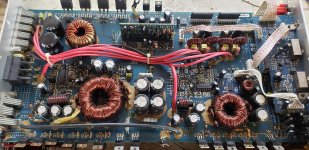
- Rockford Fosgate T1500.1BDCP (regulated at 1900W/1800W/1200W at 1/2/4 ohms respectively)
- Final impedance is wired to 1-ohm
- ~200L 4th/6th order adjustable enclosure

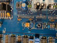
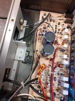
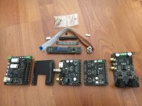
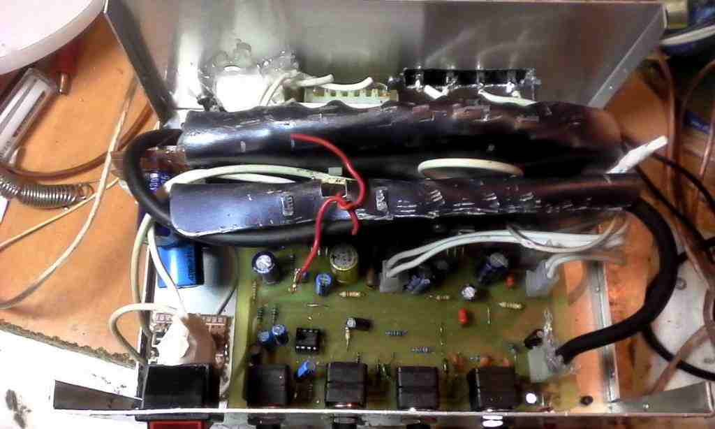
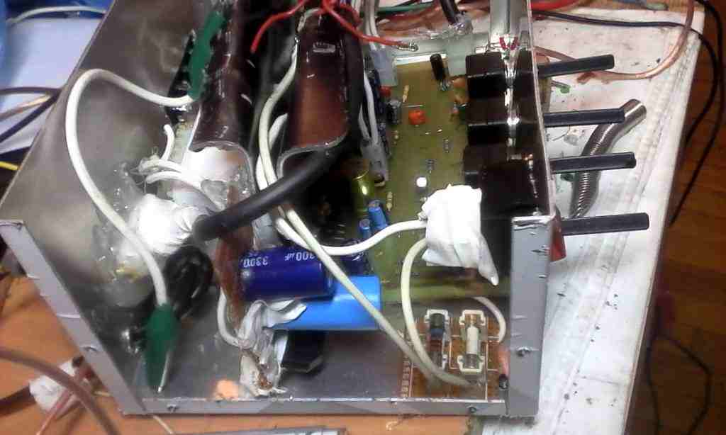
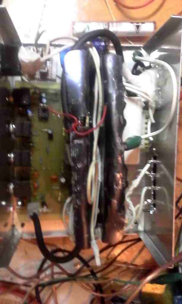
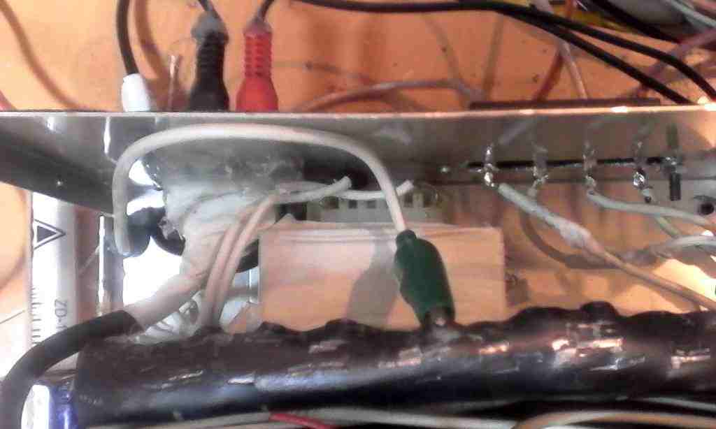
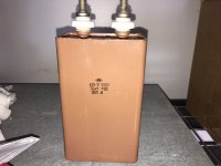
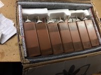
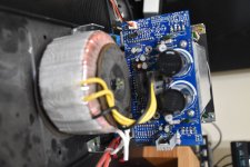
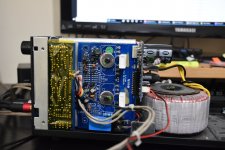
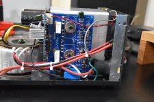
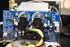
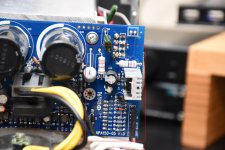
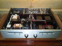
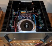
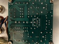
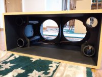
The enclosure is built as a series BP6 with following specs and pictures below:
- Rear chamber: 55-61L (depending on port configuration)
- Front chamber: 125-131L
- Internal ports comprise of four 46cm long PVC pipes which can be capped off to modulate internal port area (~0/45/90/135/190 square centimeters of port)
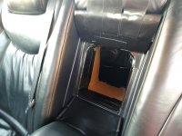
- Front port is 27cm long, with 489 square centimeters of area. In front of this there is another ~10cm of effective length having an area of ~900 square centimeters where the arm-rest recesses.
attachment.php

attachment.php


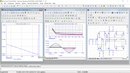
Enclosure has been modeled in Hornresp taking into account all port configurations and corresponding displacements @ 1kW RMS. Overall, the response of the box with the cabin gain is close to expected as we see in the RTAs that follow.

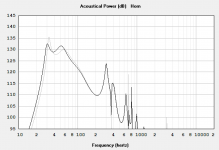
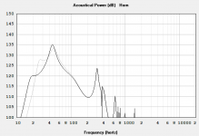
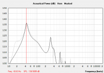
Below are Hornresp graphs which show the five different configurations:
4 ports open vs. 3 ports open
2 ports open vs. 1 port open
1 port open vs. 0 ports open (4th order mode)
attachment.php

attachment.php

attachment.php


I've taking many measurements with UMIK-1 at relatively low volume (well within any limits of microphone clipping). I'm noticing an intricacy in 4th order mode as well as 1 and 2-port 6th order modes that deviates from the sims in regards to peak output. Based on modelling I'd expect it to peak harder than the next closest configurations (1-2 ports open) by ~2-4dB respectively but that does not appear to be the case. At much higher power (1000W+) I've also RTAd the vehicle with the mic outside the window (in order not clip the mic inside the vehicle) and the same discrepancy is observed.

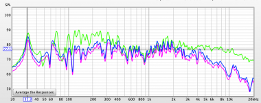
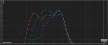
First set of measurements are with front windows open with UMIK at headrest (probably less than <5W). Box configurations can be identified by their low-freq shelf.
Green: 4 ports
Light green: 3 ports
Orange: 2 ports
Purple: 1 port
Blue: 0 ports (4th order)
attachment.php


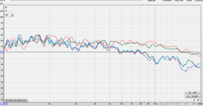
Second set of measurements are with all windows open with UMIK outside of car, ~1m away from B-pillar at same power. It's clear the car has optimal resonance mode at ~46-47Hz which is the the rough range where I'd like to target for peak SPL. The trace colors are different in this chart.
Green: 4 ports
Orange: 3 ports
Purple: 2 ports
Dark green: 1 ports
Red: 0 ports
attachment.php


For anybody wondering on why I want it to peak harder, it's to optimize this enclosure in these port configurations for SPL competition. I like having the modularity to switch port configurations on the fly for when I daily drive and when I want to compete. For reference before I got the UMIK, for competition I set it up as a 4th order and on the first go it did a 146.1 @ 42Hz on a Termlab at around 1kW of power. Now with the UMIK, I now have more insight into what's going on and I'm wondering if 4th order may not be optimal regard to SPL.

Was hoping to get some insight as to why this might be happening.
In terms of some factors:
- I don't believe that it's port compression as this relative behavior happens at low volumes. Furthermore, even at ~2kW there is no audible noise from the port.
- Could it be impedance being drastically difference in 4th?
- As this is done at low power I doubt I am seeing large-signal driver effects relating to BL-change vs. excursion as the drivers are barely moving when taking these measurements.
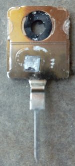
- For sealing up the ports, I am using slip-on 3" PVC test caps (very elastic). They don't leak but I do know that they are thin enough to resonate but I'm doubting this is significant.
- Could there any issues with the bracing/port supports/ports causing some tuning effect inside the box (only thing I've considered is just their displacement)?

Attachments

  • box1.jpg
    box1.jpg
    221.6 KB · Views: 515
  • box2.jpg
    box2.jpg
    234 KB · Views: 525
  • 4to3_ports.PNG
    4to3_ports.PNG
    62.1 KB · Views: 392
  • 2to1_ports.PNG
    2to1_ports.PNG
    58.7 KB · Views: 381
  • 1to0_ports.png
    1to0_ports.png
    63.3 KB · Views: 365
  • RTA.PNG
    RTA.PNG
    179 KB · Views: 374
  • rta3.PNG
    rta3.PNG
    249.7 KB · Views: 376

Rotel RB-991 clicking/popping

Hi,

I'm having problems with my amp again and was hoping for a few pointers.

I started to get popping/clicking on the right channel.

I unplugged the speaker from that channel and finished my film.

When I checked it next day, both of the 6.3 fuses were blown.

Only other symptoms I can think is it occasionally used to click when powered up, but this has gone since I'm only using the left channel.

Any tips?

I'm happy to reward any advice that leads to a fix.

I'm an electrical engineer, but electronics has always been my weak point (well that and personality).

No oscilloscope, but decent multimeters.


The schematic is too large for forum upload, but I can send it to anyone.
Also if you search for rotel rb-991 technical manual it comes up in images.

this link may work

rotel rb-991 technical manual - Google Search

SKA AMPS GB150 kits/complete build

Hi All,

i've read about Greg ball's popular GB150 amp a few years ago...
and just recently was thinking about one again...
upon trying to go to the ska-audio site, i noticed it was gone....

greg's not doing this anymore, emailed him to confirm....

I was wondering if there any verified kits which exist on the interwebs?
all i could see was a thread for something based on the GB150...caled the tg7? on diyaudio.


i was hopping there were pre-build modules which i could take to a tech to wire up/box for me (seeing as my diy skills are still not at the mains powered level yet! )

Upgrades for Rotel RB-991 Power Amp

Hi Guys,

What are the recommendable Capacitors, resistors or any other parts would be recommendable to select for a best possible quality / price ration upgrade to Rotel RB-991 Power Amp. I think they where manufactures starting from 1999

The Amp uses: BHC slit-foil capacitors. It circuit employs Black Gate and Wima capacitors and Roederstein metal-film and Vishay military-grade resistors.

Also, what are the signs to look for if power amps of that age needs upgrades? although is it really necessary to upgrade 1990 + Rotel Amps, meaning would the caps and other parts lose their ability?

Thanks

Rotel RB-980BX and RC-995 upgrade

Hi
I read forum for a while and notice you have expierience with Rotel .
I have 2 pieces from that Company .
Power Amp RB-980BX
And Preamp RC-995
I have aquired them few months ago and they are in working order however sometimes channel play unevenly and power amp gets very hot. I have cleaned pots and selector desoldered of the board dissmantle and cleaned as well as relays in pre.
However in order to improve on the equipment i would like to recap them as a prevention .
Basically i would like to ask you for help with capacitors selection and perhaps a suggestion as what else may need attention . Its all still original black gate. Perhaps i should just do power caps ??
Which capacitor cause problems in zobel network i read in one of your post??
Electronics is very new to me but i know how to use meter and soldering is good fun for me .
I would appreciate your help.
Love Rotel Sound and would like to preserve it.
Best of Regards .
I have both service manuals if needed.

Help with Rotel RB-980

My RB-980BX was stuck in protection mode. I checked every component on the circuit board, replaced a couple of resistors that were slightly out of spec and replaced all the smaller caps. I could not find any issues with the output transistors with my DMM or the four large caps so I left those as is. There are 4 internal fuses and they are all functional. Rail voltages are OK and transformer voltages are spot on. No obvious signs of burnt out components or damaged board from heat. Still stuck in protection. Any ideas as to what could be the problem are welcome!!!

Specific DML Questions

So ive built a couple sets of flat panels with canvas pictures and they sound great with a seperate sub matched with them. I am thinking about building another set for my garage shop and I have a couple questions.

1. these are just for garage work shop so not looking for perfect amazing sound but do want them to sound good cranking up the tunes while I work. I have 2 large canvas pictures that are 30x46 that i was debating suspending from ceiling down firing so as to not take up space because my walls are already covered in other stuff. Will this sound decent down firing like that? its a standard 2 car garage

2. using these very large canvas 30x46 what type and size exciter should I use? should I do two 4ohm exciters on each to pair them to 8ohm? I have a yamaha audio video receiver that im using for my computer sound in the garage that I can power these with. I think 100 watts per channel and the receiver is actually designed to be programmed and used with either 8ohm or 4ohm speakers. I can even bi amp if I need to with this receiver

Considering an ESP P3A but what else is popular?

Hi

I've built a number of chip and D-class. Looking for a new project with equal or greater power to the lm3886.
The only SS amp Im familiar with is the ESP P3A but it's not mentioned very often these days and last time I checked PCBs were a bit expensive.
Is this still a great amp, what else is recommended?
- ideally cheap to build
- 60-100w is plenty.
- 4/8r suitable
- Happy to build a clone or buy from China etc

Tannoy Super Red Monitor Project

Greetings,

Ohh JOY ... !!!

I bought myself a set of Tannoy K3149 speakers (Tannoys Dual Concentric 12") in mint condition. It came with 1 filter 😱 and 2 filter frontpanels 😛 .

Always wanted Tannoys for my (ever to build) home studio. Now I have this pair, I intend to do a project;

1 - Try to build my own Super Red Monitor cabinets (as close to original as doable)
2 - Design my own version to make it go way more deep, but keep it easy enough to handle.
3 - Build new filters, with the latest and greatest components (affordable prices ?)
4 - Do an active version with miniDSP and class A amps.

Challenges enough, I found a number of web-sites that contain K3149 and Super Red Monitor data, including a schema of the filter used.

To my supprize, the T&S parameters found ALL differ, and not by a margin. I use Bass Box 6 Pro, to design my cabinets (with good results) and it also contains a 12" Tannoy (SRM 12 LF), but it holds a note (caution: These parameters were measured by an unknown source (never knew that an unknown source has this type of talent...😀) and may not reflect the original specifications of the driver.). These parameters ALSO differ from the others found, but seem "More logical".

I also found the dimensions of the Super Red Monitor cabinet, 2 sets almost identical, 6 ALL differ, like internal volume between 72 and 105 liters. Doing a conversion to feet 3, AGAIN 3 differ this time. Hmmmmmm, nice little project popping up on the horizon.:warped: (or is measuring and calculating way more complex than expected? 😀
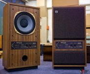
I gave it a first shot with Bass Bax 6 Pro, using the "unknown source" SRM 12 LF driver and the 2 almost identical dimension specs. Gave a result that looks very much like the specs in the Tannoy brochures I found.
Except to the reflex port, looks small on the picture (compared to the 12" driver it looks more like 50-60 mm), but comes out to be 98,8 mm diameter and 18 mm deep (at Fb 52 Hz).

I could just build these and have a listen, but my goal was to do it VERY right.

So this thread is intended to find all details and show all results, ending in designs for all interested parties (except professional builders, you can find this yourself.).

Any suggestion where to get the REAL T&S specs? to start with. Also saw that Tannoy (and almost any other company at that period) used "particle board" as building material, which we now a days call "any unkind phrase" of wood.
Start will be MDF 18 mm, end will be top grade Birch Plywood. Heavy bracing, etc.

Also noticed VERY thin cabling used, see how that effects the sound quality. These were very popular monitors way back when, change it YES / NO?

Keep you informed....

Oooh , by the way, the picture attached of the complete cabinet of course is just an example of what will be the net result of this project. Duuhhh.

Attachments

  • 1036121-classic-tannoy-super-red-monitor-srm12x-dual-concentric.jpg
    1036121-classic-tannoy-super-red-monitor-srm12x-dual-concentric.jpg
    230.5 KB · Views: 1,754
  • $_85.JPG
    $_85.JPG
    52.1 KB · Views: 1,614

Converting Mission Cyrus 2 to a power amp

Hi all,

I have a Mission Cyrus 2 that I would like to modify so it can be used as a power amp only, now I know that it’s preamp stage (besides the phono stage input) is passive so basically as far as I understand I only need to bypass it volume potentiometer.
But the thing is that as an integrated amp with passive preamp stage the power amp stage probably has a higher input sensitivity than an active preamp stage so I assume that if I’ll just bypass the volume pot and connect an active preamp (tube preamp in this case) to the power amp stage it will overload the Cyrus 2 power amp stage input, any suggestions for where in the input circuitry of the Cyrus 2 should I connect the external active preamp so the power amp stage won’t be overloaded by a too high of an input signal from the active preamp?
I’ll include the Cyrus 2 schematics soon.

Thanks

NAD 802 tweeter problem

Hello,

I have a pair of NAD 802 speakers and although I like the sound of them I think that one of em has a tweeter problem. I (think) I can hear somewhat of a scratchy sound sometimes. It's not permanent but at certain frequencies it makes me wonder if the tweeter might be either damaged or misaligned or something else which makes this scratchy thing at "mid frequencies". Are there ways to isolate this problem to be sure its even there and not just in my head? And even more important...are there solutions I can try to fix this? If not, is it possible to swap tweeters with other speakers if the parameters are identical or is there more to it than the obvious like size, impedance, power rating etc?
I'm going to exchange left with right speaker now and see if its still there or if it is indeed the speaker but thats all I can think of in order to figure things out.
What I noticed is that both tweeters seem to be slightly cracked around the screw holes and I already aplied a bit of glue to the craked parts but could this even be a source for scratchyness or could it even be a problem with the crossover capacitors ? I dont remember if I recapped them, will have to open them and have a look inside...
As you have probably noticed I'm a bit clueless when it comes to speaker healthcare 🙁
Thanks for any advise and have a great weekend!

How to select a replacement MOSFET/transistor?

How to select a replacement MOSFET/transistor?

Regarding a recent post,

Is this the correct method to select a replacement transistor (when the one on the board is discontinued or unavailable to purchase)?

My method:
1) Match the transistor type (NPN or PNP).
2) Match the "Vceo" voltage.
3) Same or higher "Collector current".
4) Same or very similar sized package.
3) buy the complimentary transistor at the same time.

Anything else I should be considering?
Projects by fanatics, for fanatics
Get answers and advice for everyone wanting to learn the art of audio.
Join the Community
507,666
Members
7,883,248
Messages

Filter

Forum Statistics

Threads
405,984
Messages
7,883,248
Members
507,666
Latest member
Fpa420