How much to spend on DSP

Hi there,

I'm in the process of sorting out all the parts to make a class D plate amplifier.

I'm looking into buying a DSP board so that I can bi-amp rather than using a passive crossover.

I've seen a few options around-

-MiniDSP
-Dayton audio
-Sure electronics

The miniDSP option is about €100, which is a bit pricey as that's about the same as I will be spending on amplifier modules. Then there's a massive gap down to the Dayton and sure boards at about €20-30.


Does anyone know about the relative strengths of these products? It's there a significant difference in the quality of the signal coming from a MiniDSP unit?

And most importantly, does anyone know of any OEM manufacturers who make reasonably priced boards?


Thanks
Peter

SPDIF out of TV low level (once D to A'd)

I have a 9th generation Pioneer Plasma and if I use the Optical SPDIF out, to any DAC the resulting analogue signal is very low.
If listening to music content it fills my room but, a little more, if watching a concert for example would be great.

When I was fixing TV's for a living, the Digital out always, no matter what Manufacturer, seemed low to me.

I was thinking of using a cheap DAC chip, using an OP Amp to raise the analogue level to say a good 2V rms and then A to D-ing the signal using a circuit similar to what must be available at the O/P of the average Minidisc unit.

Thoughts and any other possible solutions greatfully received.

P.

Schematic for REL T-3 (and a few other questions)

Anyone have a schematic for the amp i an REL T-3 subwoofer?

My T-3 is blowing fuses. I'm pretty sure the output transistors are shorted. The appear that way when measure in the circuit. I'll pull them today and retest.

In tracing the circuit, it does not appear that there is any voltage regulation for the output transistors. Current flows from the transformer to the PS caps and then to the transistors.


I can't find any VR ICs on the board, though there is one op-amp that could be in a part of a VR circuit.


Is it comment for outputs to be driven from an unregulated source?

Finally, assuming the transistors are bad and a replace all 4 (2 NPN, 2 PNP), are there any guidelines for setting the idle current if I don't have a schematic or manual? Should I just leave it as is in that case?


thanks,


James

Overture design guide issues with heatsink and voltage

Hi friends,

I've got my LM3886 stereo system running now for a test and I re-checked the Overture Design Guide spreadsheet after double-checking the supply voltages.

I'm not sure if I should be worried about the supply voltage being +- 38.5V, which leaves 3.5V headroom. Should I be going for a smaller output voltage on the secondaries on the transformer (currently 25V)?

It also seems to think that the heatsink is going to cause me trouble. I've felt the heatsink and it feels lukewarm after 30 minutes of listening. Does this mean the design doc is wrong or I am not outputting 100W ?

I've filled in my values in the spreadsheet and attached the screenshot below.


EDIT: I've got thermal paste on one chip (the other will be done in the next few days), and no insulation washers. I've got the TF package, the one without the metal tab on the body.

Attachments

  • Screenshot_20210810_165300.png
    Screenshot_20210810_165300.png
    155.1 KB · Views: 271

Please Help me identify these speakers

Hi there folks I recently bought these old speakers ,they seem to be coaxial speakers .I have spent 3 days on the internet trying to find out what brand of speaker they are without any luck so i can repair the high frequency drivers in them .The high frequency drivers are very small compression drivers with 25mm phenolic diaphragms ..the person i bought them from says they were built around 1965ish..if you can identify them please let me know so i can save these speakers...thanks in advance folks
Ill add the photos as soon as i can work out how to upload them here

LC & LCL DC Filament Supply: The Choosing of the Choke

Evening all,

I've been embarking on more elaborate power supply designs, while going through Thomas Mayer's blog bit by bit. I'm wanting to include in my next build a choke input filament supply such as these examples, from his blog:


76aDhDr.jpeg


J1kCuwU.jpeg


So I'm shopping up the components that aren't just on the shelf, and that means just the high current chokes... I won't be using 220, and it will be 5v from the transformer to 2.5v filaments @3amps for two 45 tubes.

The questions I have are:
1. What is the motivation to use a high-quality choke in this position, eg a $150 Lundahl? Why would I not use an $8 toroidal from mouser with the same inductance and current ratings? Is wire gauge important? Why wouldn't we all just go out back to that dead washing machine in our yards, pull the motor and unravel the wire, fetch a nice stick from the woods and wrap ourselves up the medieval clay-pot battery-accessory of an inductor that we all can have for free?

2. Will precise inductance matter much at all in this position? As long as DCR is right, am I correct that I can use a wide range - and would it be correct that I can go ahead and stick to the low end of that range, to minimize size without impacting the function? Say, 1 to 10 mHy?

Thank you in advance for any information. Links are quality input in my book.

Modifying 100 watt LXI amplifier circuit

Hello every one, I would consider this my second major solid state amplifier project, but with this one it will be like rebuilding an entirely new amplifier, so I am making an attempt to make the best one I can from what I've salvaged from this one and whatever else I can find in my junk piles.

The amplifier is made by Sears (go figures, considering there is no info what so ever about it). It produces 100 watts into 8 ohms and consider how cheaply made it is, it sounds really good and is a well designed amplifier. I even took the time out to draw up a schematic, which can be used for the convenience and personal use of others.

I have many ideas in mind of how to modify the circuit for improvements, but only understand the basics, so I am looking for ideas of what would make this circuit better, more current capable and efficient.

I have made a few posts on the Class "A" Hybrid Amplifier thread but have not had much help there since this is a class "AB" amplifier, that I indeed want to turn into a Hybrid of some sort, mainly to get rid of the obsolete chip fet at the input stage of the amplifier, so I am more than willing to be walked through the modifying process, as I now have all SUMMER!!! 😀

Here is the original schematic that I drew up, if there are any reasons why what I drew up may not work please let me know! I will correct it as necessary. 🙄

Attachments

  • lxi amplifier(small).jpg
    lxi amplifier(small).jpg
    66.9 KB · Views: 980

FS: 7 & 9 Pin Tube Socket Extenders/Adapters

I'm offering a set of (1) GC #9243 standard 7 pin and (1) GC #9244 standard 9 pin tube extenders, each labeled "TV tuner socket adaptor." Both are about 2 3/8 inches high. Other than a bit of tarnish on some socket pins and test terminals, these are in nice shape and are tested & working.

$28 for both, free First Class USA shipping included. PayPal only.

Attachments

  • upper_view.jpg
    upper_view.jpg
    406.7 KB · Views: 97
  • lower_view.jpg
    lower_view.jpg
    316 KB · Views: 94

Yamaha CA-610MKII Restoration/upgrade

I'm looking to renew my Yamaha CA-610MKII. I've had it since 1996.
It is from 1977 I think and is all original and works.
Looking at the Schematic, none of the transistors are available unless you go on ebay. I don't have a problem replacing capacitors as they are available.

I found this website that someone named S.Kinder renewed one but left out cross-reference parts he used!

Vintage Hi-Fi Audio Restorations: S.Kinder's Yamaha CA-610 MKII Integrated Amplifier Restoration

I like what he did and there are a few transistors in the pics and reading that show what he used and are available from mouser/digikey.

So I made a list of part numbers and the substitutes that I think will work. Took me all day!

I'm asking for help if anyone could verify my selections are good and if not, please let me know of alternatives.

I really want get this unit a little more current as far as parts.
For the cost of the replacement semi's, I think it's worth it.

Please let me know, any help would be good...

Thanks all

Attachments

  • Screen Shot 2019-02-22 at 10.21.11.png
    Screen Shot 2019-02-22 at 10.21.11.png
    588 KB · Views: 364
  • Parts.jpg
    Parts.jpg
    148.5 KB · Views: 310
  • ca610_ii.pdf
    ca610_ii.pdf
    2.3 MB · Views: 163
  • Parts.txt
    Parts.txt
    772 bytes · Views: 150

What is going on with the price of valves!?

I'm a casual observer of valves on eBay, just noticed this £1500 (2000 USD) auction. Maybe I don't have the nose for a bargain but just seems like a load of TV/radio valves. Could not see any of the crazy price audio things. Well I suppose it's £1 per valve. So not bad value. I just surprised someone would pay so much and need so many!


Very Large Collection of Old Radio Valves | eBay

Attachments

  • Screenshot_20210822-191631.png
    Screenshot_20210822-191631.png
    752.8 KB · Views: 813

DML as surrounds for atmos theater?

Greetings from an interested newbie to the DIY speaker realm.

I am going to be building a sub set up to sort of match some furniture.

The rears don't have many good options as far as a match goes but if a DML could serve well as a rear surround I have some decent options. The ceiling speakers can be worked around in a few ways but DML might be pretty interesting for that application as well.

Sorry if this has been previously addressed I looked around a lot and used the search function however I didn't find any discussions on it.

Is this a stupid idea because the surround effects are supposed to be lower and DML's are going to be too "loud" when driven by the decoding Amp?

My limited general understandings would be the DML have little bass response below 150htz is that a concern with surrounds? My experience is pretty limited and involved pretty crappy surround speakers in the past. Some Polk cubes that honestly never really sounded much better than an 8 dollar RadioShack 9 volt transistor radio.

Thanks for any feedback.

Questions related to using Cadsoft Eagle-help available

Hi all,
I want to start this thread to answer questions related to using cadsoft eagle effectively. I have been using eagle for over 2 years now and done many layouts of single sided and two sided ones. Although sprint is preferred by many to make simple analog layouts, I prefer eagle because of its compatibility with schematic.
All you need is a carefully checked schematic and correct devices, voila you are guaranteed to have correct layout.
I dont say i have mastered eagle, but i would say i am about 60% proficient.

I still have no capability with making ulp's. never felt the need to, as there are many many ulp's available on internet that get the job done.

This is not going to be a tutorial thread, just question and answer thread.
and would cover questions related to the following topics
1. making sch
2. cloning an sch
3. making packages, symbols and devices
4. making layouts
5. Cloning layouts
6. importing gerbers for cloning
7. DRC for home etching and for manufacturing
8. generating BoM
9. Generating gerbers
10. Generating pdf's (positive images and negative images of solder masks and copper layers), mirroring them, etc
10. any other

In the process of answering questions, this thread hopefully will also lead to make me more proficient in eagle and help in finding something new which I hadnt used before.

Thanks and regards

Prasi

Korg B1 + S11 Regulated PSU

Hello,

I have a Korg B1 + S11 Regulated PSU for sale.

Korg B1 with best parts: Nichicon, Takman, Black Gates NX, TKD Poti, Elma Switch, Cardas RCA Connectors.

The S11 PSU is in my opinion the best option for the Korg B1.

The aluminum front plates are powder coated.

The price for both is 400,- € ‚ plus shipping.
I can unsolder the 6 Black Gates NX and reduce the price to 300,- €, plus shipping.


Kind regards

Andreas

2SK76 2SJ26

Hey guys, I need a favor if someone is willing. I have these parts and I think they are suspect, I got them some time ago from a vendor I have had luck with in the past, but I have limited curve tracing available to me. I have a total of 8 parts that I'd like to get tested.

I would be happy to pay if someone has a curve tracer capable of checking them out and matching.

PM me if you are willing and we can discuss the parts and payment.

Thanks

JT

Dayton PC83-8 (3") test results

I picked up a couple of these new Dayton 3 inch poly full ranges Dayton Audio PC83-8 3" Full-Range Poly Cone Driver for testing. I thought I share the results here as they were designed as a full range.

I was curious about using them as a midrange, the spec sheet indicated they should have a wide dispersion up to around 4KHz. They'll also do double duty as a test speaker an active cross over project.

The tests are geared towards off axis performance, distortion, and I did EQ them and listened for a while. The cobbled up enclosures will be sufficient for that purpose.

Index to trials:
1) Box 8L - Dayton PC83-8 (3") test results
2) Cylinder 4L - Dayton PC83-8 (3") test results
3) Box 8L + large baffle - Dayton PC83-8 (3") test results
4) MLTL - Dayton PC83-8 (3") test results
5) Omni opposed drivers - Dayton PC83-8 (3") test results
6) Le Cléac'h 7-Petal Horn - Dayton PC83-8 (3") test results
7) Le Cléac'h 11-Petal Horn - Dayton PC83-8 (3") test results
8) Fixing the Le Cléac'h Petal Horns - Dayton PC83-8 (3") test results
9) BP8 'subwoofer' to get some LF performance Dayton PC83-8 (3") test results
10 ) Bass Reflex - Dayton PC83-8 (3") test results
11 ) Tractrix Rectangular Horn - Dayton PC83-8 (3") test results

Bleeding resistor + led

Hi,

I'm building a phono tube preamp from Valvewizard:

The Valve Wizard

With this power supply:

The Valve Wizard

I'm using the last schematic, without the voltage doubler. But I've notice that the 100k 2w resistor it's getting very hot.

My B+ voltage is 350V

And I use a switch with 12V led:

Aluminium Switch with Blue Light Circle 2NO2NC 250V 5A O19mm Black - Audiophonics

So, If my math's are right. I need a 33k 5w resistor?

Thanks.

Pioneer FX-88-ZI Tuner

This Tuner is an integral part of my Mum's system.
It has stopped responding to most of the buttons.
Free download pioneer fx 88 zl service manual
From the schematic, the buttons, all tactile switches not capacitive, all connect to the micro-controller.
I suspect the limit of my ability will be to ensure the mcu is receiving +5V.
Is there anything else I can possibly test for?

When on a station it appears to work perfectly.

2 small sub-bass modules driven by 1 plate amplifier for home office?

Hi

After recently converting to 2 smaller (BK) subs for my main 2 channel system, I am wondering about building a powered bass system for my home office.

The components I am considering are:
2 x Dayton Audio DCS165-4.
Dayton Audio - DCS165-4 6-1/2" Classic Subwoofer 4 Ohm

1 x BSB200
BSB200

The amp is rated at 200w RMS into 8ohms/275 into 4 and AFAIK is what they use in their XLS200 subwoofer. The drivers are 100w/4ohm items.

My plan is to build all three into separate cabinets for flexibility - the sub cabs (small and sealed - not ported/PR etc.) will be stackable if that works best or could be positioned separately for optimum smoothing. The amp will have a separate accessible position. I plan to wire the subs in series (100w each).

The space under my desk is limited, hence small cabinets - I have had a BK Gemini II there before but it was impractical. I’m not trying to produce really low end, rather to support/smooth the area from mid 30hz up to the 65-ish area. The benefits in terms of soundstaging etc. of dual subs in my main system have been considerable and I would like to reproduce this effect if possible in the office system. The main speakers (on the desk) are Mission 731i and amplification is either an AVA Meastro 50 or an Arcam A18.

My main question is whether driving both drivers off a single plate amp will be an effective solution? Also, has anyone else done a similar build - effectively 2 compact passive bass modules driven by a single amplifier?

Regards

Alex

Replacement midrange driver calculations

I have an active 3 way (Linkwitz Riley) speaker system with 6 60W amps, using Vifa 013-wh-00-08 as the mids. One of them has died, Im looking at replacements.

Vb for the Vifa is 2.2L, and so is the actual mid enclosure. I was contemplating Peerless 830860 as they get good reviews, which would fit with a bit of woodwork - its slightly larger and has flat edges.

For the Peerless a Vb of 4.8L comes out of Unibox. But since I cross over at 200/300Hz Im thinking an actual Vb of 2.2L wont make much difference. Is that a fair assumption?

But a max power input of 14W is suggested (The Vifa design comes up with 40W). Im thinking that means this driver isnt suitable for a closed box design? Or is that only going to be an issue if the design is used for bass/woofer ie not rolled off at 2/300Hz?

Any guidance is welcomed.

Looking for Harman Kardon hd7600 parts.

So, I bought a Harman Kardon HD7600 CD player to match up with my HK amp and tuner handed down from my parents, but lo and behold, when it arrived it no longer functioned. Many hours of fruitless searching and trial and error, I have a pretty good idea what's wrong, but I need to find an assembly that doesn't appear to be available anymore (pics below).

Does anyone know where I can get one of these, or even just a replacement spindle?

The player itself appears to work fine, but in its current state it simply spits CDs back out and refuses to play.

Also, is there a forum where I can get help with troubleshooting?

Single gain stage transistor amplifier.

Hi All,

Completely new here,
I've gotten hooked on this DIY audio amp building.
My goal is to replace a Marantz 2226B with a DIY integrated amp. So far I have had good results, but not enough to beat out the Marantz ( it may never happen). I have 90db speakers and can blow go too loud with 4-5 watts. Personally I like lower watts.

So I have tried the Chip amps...but I love the simplicity of a Single ended amp. To me there's no sense in creating a class A/B chip amp if I already have a Class A/B amp...that sounds good.

So I want to find/ develop a circuit that uses a single gain stage single ended transistor amplifier. I had a darlington amp work...but not enough volume. I'm trying to stay away from mosfets- I always come up with more distortion on the simulator with mosfets...and seems to give me a headache when played...awsome transparency though...just too sharp on the highs.

So am I trying to do the impossible? I don't want to rock the windows to a rattle...detail is more important.

Thanks for reading this and for any help you may have.

Solid state R2R attenuator using analog switches or multiplying DAC

I'd like to get opinions on building an attenuator that uses modern analog switches or a multiplying DAC. I've seen this method mentioned a few times and one example of a finished product but it seems it is still rarely done by the DIY community.

After searching through the forums there seems to be a lot of opinions on solid state attenuation but it looks like much of it is not based actual experience. It also seems that analog switches have a reputation that was gained 10 years ago but the analog switches available today are quite different, some having RON of < 1R.

The basic principle seems to be: VI conversion > R2R attenuation > IV conversion. There are quite a few very high end preamps that use this method, eg:
- Mark Levinson 32 and 38 preamps: Pic here.
- Luxman Luxman Electronically Controlled Ultimate Attenuator (LECUA, used is multiple products): Details here
- Accuphase AAVA: Discussed briefly here.

bbp built one, details here and here. Looks like it achieved very good results but he never shared the whole schematic.

While these implementations might sound complex with many analog switches and some ICs to control them, the same can be achieved with a single DAC and Opamp IC. Mark Levinson also does this. BV has mentioned a couple of times that he has achieved good results with DAC8043. It is detailed in the datasheet in figure 3 (VREF is the input):
qpFMHNV.jpg


Here is an Analog Devices Circuit Note about using this method for attenuation: Circuit Note | CN0025 | Precision, AC Reference Signal Attenuator Using the AD5546/AD5556 Multiplying DAC | Analog Devices

The DAC8043 might be good for testing as it comes in a DIP package but there would be better options once it was tested, like using AD5439 with ADuM7440 (SPI isolation) and a OPA1612.

I've attached a schematic using a DAC7800 and a dual opamp.

What do you think? Anyone experimented with this? An SPI controlled 1024 step attenuator that is better and more flexible than a PGA2310 and easier to use than a CS3318?

Attachments

  • Untitled.jpg
    Untitled.jpg
    99.3 KB · Views: 4,232

Amp Design Question

Morning, I’ve been looking at the schematics of B&K and other mosfet architecture amps and it seems each new design had more mosfets. My AV5000 S2 has 4, the AV125.5 that replaced it had 6 and my old REF7250 had 10 per channel. That means to perform the same repair I’ve done to the AV5000 on a REF7250 would be a total of 50 mosfets, for 300 solder joints! Is the increase a matter of making the mosfets work less by splitting the amplification between more components or is there an increased quality of sound by additional power transistors? Or both?

Bi-amping Dali Ikon 6 with a Minidsp 2x4hd?

I've got a pair of Dali Ikon 6 and will be getting a Minidsp 2x4hd- one pair input, two pair output (mid and bass). The Dali have 2 mid drivers and 2 tweeters, and are able to be bi-amped.

Can I sent one output of the minidsp to the tweeters and the other output to the mids? Good idea or bad? I'm new to DSP

edit: sorry if this is the wrong sub-forum. I didn't want to clog up the others with a non-diy question

Power conditioner build

I’ve rescued this old Leitz power supply from a container at work, it was used to power some kind of scientific equipment. Something had leaked inside of it, so I’ve gotten rid of all (weird!) stuff that was inside.

I’m now building a power cleaner out of it instead, and since I'm a complete beginner I could use some comments and help 😱

Inside it I now have a number of FO-felix’es. For a little bit of experimenting I’ve set them up differently; the ones with red coils I believe are 3A max (220v), the ones with copper coils are 18A max. The one with ATL written on it is a DC blocker, apparently potentially useful when used with a transformer. 2 of the boards are in line for mounting.

The big challenge I have is that I don’t have and cannot get earth in my apartment. All power outlets are only 2 wires 220v, phase and neutral. Naturally the chassis therefore cannot be earthed either.

All the pcb’s are fitted with nylon stand offs, but they are not yet screwed to the bottom of the enclosure.

I’ve fitted an IEC inlet with a fuse, and every FO-felix also has a fuse (after I bought all parts I’ve come to realize that I can’t even draw 18A from my outlets, so I could have used coils with lower rating but better supression of noise. And the 18A fuses seems to be redundant, as the mains fuse in my apartment would blow before these).

Does it look ok safety wise? Or am I lucky to be alive? Any tips or anything I should pay special attention to? Would safety be better if I used wood for the floor too?

Thanks !

ps1.jpg

ps2.jpg

ps3.jpg

nad 3130 Centre voltage adjustment issue

im having trouble adusting the centre voltage on one channel only, which currently sits outside of the specified ranges of 0v +/- 30mv (currently varying up and down between 40mv and 50mv ) so i dont want to leave it.

the idling current is within limits, so thats ok
soft clipping has no infulence, nor does the impedence switch


with the solder short removed the pot is having no influence.
I have spares of these so ive elimintated that as it is perfect 0-1k


when you turn the amp on it works ok, so its a bit tricky tracing this one
ive checked for all the obvious things visualy, but i dont want to start pulling loads of components out unessesarily unless i realy have to as i could do more harm than good.😕


any ideas?


cheers

Attachments

  • 3130 centre voltage issue.jpg
    3130 centre voltage issue.jpg
    216 KB · Views: 224

very very simple DJ mixer aka summing amp?

Hi there,

I was going through this DIY DJ mixer thread on the forum, and I noticed there was some talk about a very basic DJ mixer set up (mancuso inspired) where say for example: you have two turntables, then you connect the turntables to two phono amps, and then you run that to I guess what would be a summing amp (??) and then run the "resulting" signal to your amp and furthermore speakers.

I thought this was really interesting. The possibility of having a very simple mixer with two stereo channels in and one (maybe another for cueing) stereo channel out as a basic unit which you could then add an isolator or filters to in the output stage could be really great. Because, once you take a DJ mixer and remove all the eqing and effects, you're basically left with a summing amp with phono stages right?

my idea was to just get two really nice phono amps (possibly tube, and yes I'm aware tubes are **** in terms of fidelity, but pleasant coloration can be nice sometimes) and then hook them up to a summing amp and then maybe just get an isolator for the master output if I want to eq it...

So, I guess I'm looking for a simple/reliable summing amp schematic someone out there might recommend. And, also, would this be possible to do with a passive summing box type setup? I don't think so right? why?

Any input is greatly appreciated.

Cheers,
ben

Tubes for sale

Sale:
6J32P — 46 pcs. for $5 ea.
6N6P — 44 pcs. for $3 ea.
6N6P-I — 333 pcs. for $3 ea.
6N8S — 78 pcs. for $2 ea.
6N9S — 9 pcs. for $2 ea.
6N23P — 54 pcs. for $10 ea.
6N23P-EV — 33 pcs. for $20 ea.
6P6S — 84 pcs. for $3.5 ea.
6P14P-EV — 400 pcs. for $10 ea.
6P14P-ER — 400 pcs. for $12 ea.
6P3S-E — 100 pcs. for $7 ea.
6S4S — 13 pcs. for $25 ea.
GS35B — 10 psa. for $100 ea.
GS31B — 7 pcs. for $70 ea.

NAD 7240 PE-state of this.

ive seen some bodge jobs, but go knows how whoever got it like this
its drawing quite a bit of current on the lamp tester, but all fuses are in tact so hopefully i wont have to work too hard with it


biggest challenge is going to be making something reasonable out of whats left of the board

Attachments

  • IMG_20210804_135803.jpg
    IMG_20210804_135803.jpg
    334.1 KB · Views: 170
  • IMG_20210804_141742.jpg
    IMG_20210804_141742.jpg
    255.6 KB · Views: 179

Help assessing a couple of modifications on tritrix TL

Good Morning,

I am brand new to speaker building (so type slowly). All of you are way beyond my ability so laymans terms would be appreciated. My first build is the old TriTrix TL. I have cut my own cabinet per the drawings and few things on Mr. Campbells site. I am trying to figure out how energy travels down the transmission line. I have read it rides on air as a wave, others sites say it moves air. I as a woodworker have the ability to change the 2 corner waveguides that are flat and direct sound like light using 2 mirrors at 45°. I am trying to figure out if rounding them will be beneficial but there are a lot of caveats possible. Should I just leave it alone or is there enough theory of how the energy travels that it will be beneficial? The 2 corner waveguides would be doubled in thickness to achive this and that would change the size of the small chamber it creates (if this chamber is actually active). Do waveguides reflect energy, as in right angles, or does energy travel down them using their sides like RF?

Thanks for any ideas
Donny

.

Attachments

  • cabinet mod 2.jpg
    cabinet mod 2.jpg
    113.5 KB · Views: 93

FS: TOKEN THF-51S NOS

Sold: TOKEN THF-51S NOS

Sold!

I'm selling a pair of TOKEN THF-51S. These were purchased from watanabetomoaki, a trusted seller of these SITs. They are not matched, but the serial numbers are close, 1X5969 and 1X5958.

I'm selling because I already have a couple of pairs these SITs, one pair in a SissySIT amp and the other pair will be used in the Singing Bush or similar SE amp, and want to fund some other projects.

I'm asking $XXX. The price includes shipping in the USA and PP fees.

Attachments

  • IMG_2515.jpg
    IMG_2515.jpg
    343.1 KB · Views: 217
  • IMG_2516.jpg
    IMG_2516.jpg
    324.6 KB · Views: 213
  • IMG_2517.jpg
    IMG_2517.jpg
    264.4 KB · Views: 204
  • IMG_2518.jpg
    IMG_2518.jpg
    301.3 KB · Views: 202
  • IMG_2519.jpg
    IMG_2519.jpg
    300.6 KB · Views: 201
  • IMG_2520.jpg
    IMG_2520.jpg
    298.2 KB · Views: 74
  • IMG_2521.jpg
    IMG_2521.jpg
    333.5 KB · Views: 64

Denon pma 510ae, static noise in left channel

Ok. Got this Denon pma 510ae amp. It has a low static (white/Pink) noise in left channel, But the music sound fine otherwise. So easiest to hear the noise when there is no music playing. The noise changes when turning the volume knob. Most noise is at about 1/4 volume and 3/4 volume. But when turning on source direct the noise rises more and more the more volume i give it. The signal path is separated in three sections. There are the input section on the main board, and a volume and bass treble balance aso on the front panel PCB connected by i wire . An Its the power stage on the main board. I disconnected the signal wires to the power stage and it became quiet. Its probably not on the main board input side either. I disconnected the left signal wire coming in from the input side and there was still noise. I put another pot parallel to the main pot, no difference. Any ideas what could be the source of the noise? Is it The tone controls?

Attachments

  • IMG_20210711_171503.jpg
    IMG_20210711_171503.jpg
    987 KB · Views: 362

Budget 300B Build Video Series

I am starting on a more adventuresome project, a 300B amp based on the classic JC Morrison 6SN7 design, using a regulated DC power for the heaters.

I understand this is sacred ground I am stepping into, and this irreverent amp I am building, using cheap Edcor iron, I'm sure will draw the ire of some, but I'm doing this for the shear fun of education and the Zen peacefulness of the construction process.

I'm robbing the iron out of a Blueglow/Kegger KT88 build I built, that I'm no longer using. The main expenses at this point is the chassis ($40), some various passives and some 300B-Z tubes with sockets ($225 on sale). I will probably end up in another $100 in misc parts if I don't melt anything in the process.

You can follow along with this build on via this YouTube playlist. Right now I've posted a couple of thought process videos in the planning stages. I've collected most of the parts, and the chassis should be here next week to dive into the metal work.

I have a feeling this one will end up in a different place than my initial planned path, but I do want to stick with a coupled 6SN7 driving a 300B as the end point.

300B DIY Budget Tube Amplifier Build Series - YouTube

DC servo with RC filter question

I am now designing a simple CFA mosfet amplifier that needs a DC servo.

The servo action is injected in the NFB node.

With the servo output unfiltered I am noticing a spike near 3.5Hz in the OLG plot. This spike is accompanied by a phase inversion.

Filtering the output of the servo with an RC (R19 20k and C6 47u) I can greatly reduce the spike and reduce it's frequency (now small peak @ 1.4hz) and phase is not severely inverted.

Increasing the value of this capacitor gives even better results (As an example see the plot with C6 1000uF).

My question is:
Does the RC filter in the output of the servo reduce it's speed ?
How high can I go with the filtering capacitor ?
Is there a drawback in using such servo ?

1st image - Amplifier circuit
2nd image - Servo circuit
3rd image - OLG plot without filtered servo
4th image - OLG plot with 47u filter
5th image - OLG plot with 1000u filter

Attachments

  • CFA amplifier.JPG
    CFA amplifier.JPG
    135.9 KB · Views: 254
  • CFA amplifier SERVO.JPG
    CFA amplifier SERVO.JPG
    51.8 KB · Views: 243
  • OLG without servo filter.JPG
    OLG without servo filter.JPG
    216 KB · Views: 219
  • OLG with servo filter.JPG
    OLG with servo filter.JPG
    223.4 KB · Views: 194
  • OLG with servo 1000uF filter.JPG
    OLG with servo 1000uF filter.JPG
    223 KB · Views: 217

Dumb Cap Substitution Question

I just built a preamp kit (Korg Nutube B1) where 10uF 25V polarized electrolytics were specified for input and output caps. Even though I used Nichicon FG's, I have enough space to plop film caps in there instead.

Assuming the holes in the board are big enough for the film cap lead diameters (big if), is there any reason why I can't swap in film caps for polarized electrolytics?

BLH for Fostex FE168e∑

Hi

i recently build my first pair of small BLH Speaker and i really like them. After listining to them for a while i decided that i need a larger pair for my livingroom. After brwosing through the possible drivers, i decided it have to be the 168ez, i really like the designe (oh and of course the 6,5 inch drivers from Lii Audio but i guess they wont fit in a horn).

Now i am looking for a fitting enclosure. As usually size matters :/ and i have looked for some enclosure suggestions that fit into my living room. I ended up with the following

-BK16 ( according to many people a suboptimal choice)
-The D1 Horn from Nagaoka ( Very similar to the BK16 but a bit larger)
-And the Fostex Suggestion for the FE 166 NV (the 168ez has a sigificantly smaller Vas than the 166 NV)

They all would fit really nice regarding their size but will they sound good with the 168ez ?

Of course i am open for further suggestions 🙂

IR2153 Soft Start

I have a problem with my diy smps for class D. Sometimes a transistor explodes when turned ON. Unfortunately, it also takes circuit 2153 with it. Apparently missing soft start circuit. Runs absolutely reliably when it survives the start.
I need to implement a soft start circuit. I found two similar schematics. Version 1 - via LED to pin1 (Red line in schematic). Version 2 - to pin3 (Blue line in schematic) Please advise me. Which is better?

Thank You.

attachment.php

Attachments

  • spst.jpg
    spst.jpg
    140.9 KB · Views: 18,217

Audio dummy load

For years I've been using a wirewound resistor with some leads and banana plugs as a dummy load for testing amps.

I thought I would buy a proper one but I couldn't find anything pre-made (MCM used to sell one...)

So in case anybody is looking for ideas, here is what I made:

dummyload.jpg


dummyload_inside.jpg


More details here: Audio Dummy Load

The chassis came from Landfall Systems, the extrusion from Heatsink USA, and the resistors (a bargain) at Surplus Sales of Nebraska.

Pete

Where to buy thick diameter cable for DIY RCA interconnects?

Hi all. I've got some rather large RCA plugs that I would like to use, but I can't seem to find any brands of cable that do a big enough overall diameter. The plugs take up to 10mm OD, but all I have are various van damme cables which are only up to 6mm and are too small to be clamped into the large plugs.

I would be most grateful if anyone could let me know where I can buy some 9mm or 10mm unterminated cable for RCA interconnects, preferably online and in the UK.

Thanks in advance.

Port Tuning Frequency & Port Volume

I'm still dumbfounded by the pair of floor-standing speakers I got for free. The driver is a Peerless SKO-165 which claims a resonant frequency of 42Hz. What would you recommend as a port tuning frequency?

The second question is a little more complicated: a single 6.5" driver in a 22 litre cabinet is a waste of space. What are the advantages of increasing port volume? I can attain a frequency of 42Hz with a port of 45 * 90mm. But can achieve the same frequency using 65 * 170mm. What are the advantages of the bigger port.

If you cite WinISD or Hornresp in a brief reply, I'll probably ignore it. In my brain the mention of the aforementioned software translates to 'I don't know'. You see, you are saying, 'There's software for that'. Unfortunately, I comically reminded that several drivers have driven their cars into lakes after blindly following the software.

Unusual Mesh PTP Amp Layout ID?

I've been trying for ages to locate pics and info on this point to point layout. Basically a friend described seeing it somewhere, his description was that all components were set in a wire mesh that stretched across the chassis of the amp, and soldered point to point, and he can't recall where he saw the image. So I don't have much more to go on, but it sounded really interesting, does anyone recognise this vague description? It wasn't a guitar amp. It sounds a bit like an unusual gainclone layout.

Irf3205 reliability?

So I just had a return from an eBay sale on an MTX RT1000D, which apparently shorted a 3205 in the power supply for no apparent reason. This was a S-D short, and it had to have happened at low/idle power since the case of the device was still in perfect condition. Typically if they fail at high power they blow the case apart and melt stuff, this one I didn’t even notice till I put a meter on it. These all came from the same batch, out of the same stick from mouser. Anyone else having reliability issues out there amid this semiconductor shortage?

A very bad Sound-smith retipping experience

I just want to share a very bad experience after trying to get my Clearaudio Concept MC retipped by Sound-smith in NY. The original cart was in a very good but used condition, still sounding very nice but I decided to get it renewed by Soundsmith based on a recommendation. After getting the cart back I noticed a significant channel imbalance but it took me 3 months before actually properly measuring the output of everything in the signal chain. The left channel was clearly 6dB down with both L and R response curves being identical. I asked them to check their work and they accepted that as a warranty claim. At that second inspection the technician (David Moskowitz) said that he found metal debris??, rotated coils and potentially shorted coils in the cart. He initially rendered the cart unfixable, just to come back next day with a message that he cart was fixed and sent back to me. I organised a second cart specialist to inspect the cart and give me his professional opinion. His conclusion was that the original retipping job was not done correctly and that the subsequent fix was just trying to mask the real problem.

I asked Sound-smith for a refund of $450 paid for the service, just to be accused that I caused all the problems with the cart by not using it correctly! Now I do not have the money or the cart that works. I can only advise everyone to be careful next time when you consider them for a retipping job and especially if you end up communicating with their technician David Moskowitz.

CFA Class A Circlotron with stability issues. Thoughts invited.

This is a very unusual thread as it is really asking for help/expertise and asking whether anyone can spot any possible issues related to problems that have appeared in real world examples of this design. I know that there is some serious expertise on the forum when it comes to design and build of CFA designs, whether you feel you could offer an opinion or make suggestions 'essentially for free' is up to you. It is quite an interesting circuit though.

It is only fair to say right at the start that only the simulation file is offered and that no other details are available. My only connection in all of this is in having been asked to try and help out.

The file has been produced by another technician working on repairing this amplifier and the people involved in the design and production of the amplifier have agreed to the simulation file being discussed. It has become a problem child.

It appears the design has had issues with 'repeatability' and problems have occurred in service. These typically manifest as high frequency instability and under some circumstances hum and buzzing which appear to be related to the times the amplifier is oscillating. The buzzing reduces as the unit warms.

Typically the amplifier may oscillate at power on and although essentially non-destructive it does burn up the 10 ohm in the C/R network across the speaker terminals. This oscillation appears to be in the 300 to 400kHz region and can be picked up on AM radio. This oscillation I believe is in the 16 volt peak region (so I'm assuming over 30 volts across the speaker terminals).

When the amplifier is not oscillating, it can be provoked by simply turning a nearby electrical appliance on/off or by switching from balanced to unbalanced operation. Should the amplifier then burst into oscillation then it seems this is sustained and it can not be stopped unless the power is removed.

There is also a low level higher frequency oscillation (around 5 MHz in the real build) that is visible when the speaker relay is not connected.

The real design seems somewhat critical on semiconductor component types used as fitting different gain groups (for example in the driver stages) changes the nature/frequency of the oscillation but does not provide a fix. Getting the semi's 'right' also seemed to fix the low level hum that some examples had experienced.

(I suspect the hum issue is related to the instability rather than a simple case of hum due to other more mundane reasons)

The simulation file should click and run providing you keep the model file in the same folder. The models are for a handful of devices and are from Bob Cordells site.

Under the upper row of output devices are two resistors used to set the bias current. This allows the user to use a lower power option when needed.

In simulation I have been able to generate very similar looking oscillation to the real world designs by adding a little parasitic inductance (20uH) to the signal feed to Q1 and Q30 base's as shown in the attached image.

The attached scope shot shows the real problem.

And that is really as far as it has got. Any insight or thoughts that anyone has on this would be welcomed.

Attachments

Clearance around a Behringer DCX?

I'm getting ready to put my system back into action.
I don't have a rack mount and need to knock something up quickly.
Unit is going into a cheap IKEA TV cabinet with only passive ventilation.
I've read the manual several times and if there is information about minimal clearances I have missed it.
Can the members here give me a quick guideline to a good minimum clearance around these units please.
Space is tight or I'd simply allow 1RU top and bottom
Thanx in advance

DSP with Asian ADAU1452 DSP Board+AD1938

Hi guys…

The site is great, and most of it is over my head. But thank you.

I am coming here with my hands help up. Help. I have searches all over. I am a total novice and most things I read have trouble understanding.

The Asian boards do not come well documented, and I have no idea what is in and what is out unless it is obvious. All the boards seem different, and this confuses me.

I have wanted to do DSP and Speaker Cross-over for many years and it is all very complex. I only want to do 2-Way Cross over and Sub. I would really love a digital in and digital our so I can use my own DAC’s.

But I think, please do not shoot me, I think this is an OK combination…ADAU1452 DSP Board+AD1938 Audio CODEC Board+USBi Emulator Burner USB Programmer | eBay

But the seller and other sellers, have no information. I really do know what all the outputs are or how to hook it up or if and where to put power.

Also, I cannot find instructions on how to use these boards with Sigma software to do all the DSP.

I have been looking for over 2 years and I am still confused.

Has anyone used this board and willing to show me??? I am no technical bloke.

Billy Bags Amp Stands,12x12, Matched Pair, Designed for Aleph 2s or Aleph 5

Pair of Billy Bags amp stands. Asking $200 for the pair.


These were designed for the Pass Aleph 2s or Aleph 5, which they fit perfectly, but of course they can be used with other amps. The usable size on the top is 12x12, with the rails adding an inch or so on each side.

I'm willing to sell just one, if you have an Aleph 5, but I'd much prefer to sell them together.

I do not have boxes for these (obviously, really, right?) so would prefer something local. But I can certainly cobble something together for shipping. I'd recommend a little plywood crate, as they are heavy and will not play well with cardboard, I don't think. (I can do that easily enough. I've got lots of plywood lying around.) That's why I've set the shipping weight to 20lbs. But shipping cost will be whatever the actual cost is, to be worked out between me and the seller.

PC Hum/HDD noise into preamplifier

I am looking for help to solve a small amount of noise, consistant with HDD operation, mouse movements, etc... Heard at the speaker and enough to be annoying.
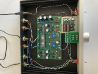
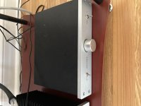
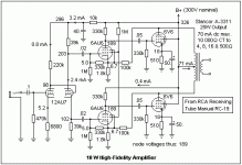
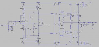
Set up is an Elekit Amp and Elekit Pre-amp, turntable and PC, with RCA out> into the Pre-amp. When listening to vinyl there is absolutey no noise, it's perfect. If I decide to listen from the PC (J-river/Flac), i.e. use a different input at the pre-amp, there is annoying humm as above. I have a power board that filters and everything is plugged into the same board from 1 AC outlet. I have tried a few of the ferrite chokes on the power cords to no avail. Pulled the PC apart and looking at the sound card, chassis, etc... I can see little screws that appear to earth everything as it should. Looked around on the forum and wouldn't know where to add a wire to stop a ground loop, if that is the issue, from occurring.
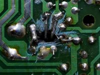
It is a recently built PC with a EV brand sound card.
My question possibly is, if the noise can't be solved, is it easier to purchase something that will use SPIF/Toslink (PC has this) in and RCA out (to the pre-amp), that doesn't reduce the sound quality, and get around the noise issue that way, or is there more I can do to solve to problem at it's source, i.e. in the PC.
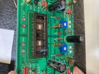
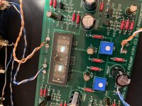
I can add images of the PC internals, etc.. if that helps.
All help appreciated as I'm fairly new to the audio world.

James

TDA2030 with transistors

Hi there!
I decided to try scematic TDA2030 as a tranzistor driver. And i have some questions about that schematic.
Did anyone do such a scheme? Does it sound normal? Will that schematic give me some troubles with installation and tuning?
Starting at what output power will additional transistors begin working?
What power supply unit should I use? How many watts?
And in this scheme, the gain factor is 10 as I understand it. Is this enough for an input signal level of 500 mV? What values of pR4 and R5 should I use?
I will definitely try this scheme. I already made a circuit board and almost soldered all the components.

Attachments

  • P3310064.JPG
    P3310064.JPG
    732.6 KB · Views: 1,589
  • P3310068.JPG
    P3310068.JPG
    916.3 KB · Views: 1,387
  • P3310066.jpg
    P3310066.jpg
    216.7 KB · Views: 1,395
  • Снимок.JPG
    Снимок.JPG
    73.3 KB · Views: 1,560

High Output Alternator

I’m finishing up my stereo system in my truck .

The last thing I need to do is install the high output alternator and battery bank .


I will be running this alternator separate so it only charges the back battery and will have nothing to do with the stock charging system this is a stand alone alt .

I tried contacting the manufacturer but never heard back .

This alternator has a external regulator.

Here are some pics but it’s been awhile since I hooked up systems .

My question is

1 terminal of the regulator goes to constant power
Another Terminal goes to ground

Then there is a terminal that goes to the field
And last terminal goes to switched power/solenoid output power .

The plug on the alternator has only 1 wire coming out .

So the question is what is the field wire ?
And what is the switched power/solenoid output ?

Wondering how I hook this up ?

I need to know what to hook the wire coming out of alt goes to
What the field wire goes to ?
And the switched power/ solenoid output goes to ?

Any info would greatly be appreciated

Attachments

  • B5E3E603-0197-46C7-B9BD-3B13B52D580D.jpg
    B5E3E603-0197-46C7-B9BD-3B13B52D580D.jpg
    993 KB · Views: 137
  • B08429B7-2C83-41B1-A9C2-0823B0066924.jpg
    B08429B7-2C83-41B1-A9C2-0823B0066924.jpg
    918.2 KB · Views: 138
  • 1ED21E8B-10B0-4931-A6BE-F8A1AD9496C6.jpg
    1ED21E8B-10B0-4931-A6BE-F8A1AD9496C6.jpg
    74 KB · Views: 140

Signal Ground Question

I've been preparing for my next build, and wanted to get the whole signal grounding thing right. I have Doug Self's book, and I have been referring to Fig 25.1 on page 600 (6th ed). I'm not sure if I'm allowed to post that here, but it is a helpful diagram.

I wanted to draw it out and see if it made sense to me, and hear if anyone has any suggestions.

My main takeaways are:


1. Local rail decoupling capacitors need to have ground at star point
2. Speaker return have ground at star point
3. NFB ground should be with signal ground


My main points of confusion:


1. In preamp, do I add an additional return path for signal ground to PSU ground on its PCB? Or, do I only allow preamp signal ground to be returned through the main amp unit and its star point? In the picture, there is no connection to signal ground to PSU ground that comes in with supply rails.
2. Is the 100 ohm resistor that separates signal ground and PSU ground at the star point necessary?


"drawing" 😱 is attached, appreciate any feedback/discussion. Thank you!

Attachments

  • PXL_20210722_204325312.jpg
    PXL_20210722_204325312.jpg
    638 KB · Views: 684
Projects by fanatics, for fanatics
Get answers and advice for everyone wanting to learn the art of audio.
Join the Community
507,574
Members
7,877,713
Messages

Filter

Forum Statistics

Threads
405,764
Messages
7,877,713
Members
507,574
Latest member
Sha1rholder