
Mona already suggested some changes. Still I post my findings here.
First stage:
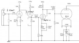
The load resistor of 1K5 is abnormally low in value (try drawing a loadline for it...) so amplification will be minimal and distortion will be high. If I'm correct the cathode voltage will settle on about 6.5 V, giving Ia = 4.3 mA and Va = 168.5 V
Second stage:
Since Va of the first stage is 168.5 V, the grid voltage of the second stage is ofcourse also 168.5 V. The cathode voltage of the second stage must be higher than than 168.5 V for normal operation (to create normal bias). This would mean that Ia has to be higher than 168.5 / 1500 = 112 mA. That amount of current ofcourse is not actually going to flow (think about the voltage drop over the load resistor of 22K and the fact that there must be some voltage between anode and cathode for the tube to operate), but there is enough 'room' for Ia to go higher than 10.7 mA, at which point the cathode voltage would go above 16 V. The cathode bypass capacitor is only rated for 16 V so big chance it will fail.
About that cathode bypass capacitor: That shouldn't be there in the first place because it will pass all AF signal to ground, so no signal will reach the third stage.
Third stage:
I think that the cathode voltage will 'settle' at about 35V, giving a current of about 106 mA and a cathode to anode voltage of about 495 V. That means the tube would dissipate 0.106 x 495 = 52.5 Watt. That is ofcourse way over the limit.
The actual current probably will be a little lower because of the 1K5 resistor at the screengrid. The actual cathode to anode voltage will be a little lower than 495 V because of the (unknown) dc-resistance of the choke. But the dissipation would surely still be way over the limit.
The anode voltage will swing up and down with signal. The voltage rating of 630 V of the coupling capacitor to the third stage is therefore dangerously low.
Fourth stage:
Not enough data.
First stage:
The load resistor of 1K5 is abnormally low in value (try drawing a loadline for it...) so amplification will be minimal and distortion will be high. If I'm correct the cathode voltage will settle on about 6.5 V, giving Ia = 4.3 mA and Va = 168.5 V
Second stage:
Since Va of the first stage is 168.5 V, the grid voltage of the second stage is ofcourse also 168.5 V. The cathode voltage of the second stage must be higher than than 168.5 V for normal operation (to create normal bias). This would mean that Ia has to be higher than 168.5 / 1500 = 112 mA. That amount of current ofcourse is not actually going to flow (think about the voltage drop over the load resistor of 22K and the fact that there must be some voltage between anode and cathode for the tube to operate), but there is enough 'room' for Ia to go higher than 10.7 mA, at which point the cathode voltage would go above 16 V. The cathode bypass capacitor is only rated for 16 V so big chance it will fail.
About that cathode bypass capacitor: That shouldn't be there in the first place because it will pass all AF signal to ground, so no signal will reach the third stage.
Third stage:
I think that the cathode voltage will 'settle' at about 35V, giving a current of about 106 mA and a cathode to anode voltage of about 495 V. That means the tube would dissipate 0.106 x 495 = 52.5 Watt. That is ofcourse way over the limit.
The actual current probably will be a little lower because of the 1K5 resistor at the screengrid. The actual cathode to anode voltage will be a little lower than 495 V because of the (unknown) dc-resistance of the choke. But the dissipation would surely still be way over the limit.
The anode voltage will swing up and down with signal. The voltage rating of 630 V of the coupling capacitor to the third stage is therefore dangerously low.
Fourth stage:
Not enough data.
plz help me fix it.Mona already suggested some changes. Still I post my findings here.
First stage:
The load resistor of 1K5 is abnormally low in value (try drawing a loadline for it...) so amplification will be minimal and distortion will be high. If I'm correct the cathode voltage will settle on about 6.5 V, giving Ia = 4.3 mA and Va = 168.5 V
Second stage:
Since Va of the first stage is 168.5 V, the grid voltage of the second stage is ofcourse also 168.5 V. The cathode voltage of the second stage must be higher than than 168.5 V for normal operation (to create normal bias). This would mean that Ia has to be higher than 168.5 / 1500 = 112 mA. That amount of current ofcourse is not actually going to flow (think about the voltage drop over the load resistor of 22K and the fact that there must be some voltage between anode and cathode for the tube to operate), but there is enough 'room' for Ia to go higher than 10.7 mA, at which point the cathode voltage would go above 16 V. The cathode bypass capacitor is only rated for 16 V so big chance it will fail.
About that cathode bypass capacitor: That shouldn't be there in the first place because it will pass all AF signal to ground, so no signal will reach the third stage.
Third stage:
I think that the cathode voltage will 'settle' at about 35V, giving a current of about 106 mA and a cathode to anode voltage of about 495 V. That means the tube would dissipate 0.106 x 495 = 52.5 Watt. That is ofcourse way over the limit.
The actual current probably will be a little lower because of the 1K5 resistor at the screengrid. The actual cathode to anode voltage will be a little lower than 495 V because of the (unknown) dc-resistance of the choke. But the dissipation would surely still be way over the limit.
The anode voltage will swing up and down with signal. The voltage rating of 630 V of the coupling capacitor to the third stage is therefore dangerously low.
Fourth stage:
Not enough data.
thanks for help.Mona already fixed it in post #2 so I'm not sure what you ask of me.
Stay at home to avoid the covid 19, so I want to make from what is available.
I am not knowledgeable enough to understand what was in #2.
i can just follow the available schematic. If possible, please redraw the circuit for me
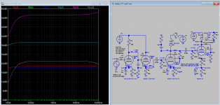
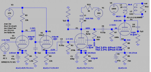
I have refined the fixs by the others and come up with a complete schematic and freq response is attached. Reference: A 211 SE Triode Amp | audioXpress
With 750 ohms cathode resistor of 211, the plate supply can be up to 1kV, dissipate 59W of 75W max. The driver current 30mA is about right, so the actual current should be higher if you run >30mA. Now as shown is 21mA-25mA, you can raise the bias level for 6p3p if you need more headroom but doing so also reduce the drive current which maybe introduce higher distortion. Take great care when dealing with high voltage.
With 750 ohms cathode resistor of 211, the plate supply can be up to 1kV, dissipate 59W of 75W max. The driver current 30mA is about right, so the actual current should be higher if you run >30mA. Now as shown is 21mA-25mA, you can raise the bias level for 6p3p if you need more headroom but doing so also reduce the drive current which maybe introduce higher distortion. Take great care when dealing with high voltage.
Attachments
Last edited:
- Home
- Amplifiers
- Tubes / Valves
- 211 Schematic - need help