I've been preparing for my next build, and wanted to get the whole signal grounding thing right. I have Doug Self's book, and I have been referring to Fig 25.1 on page 600 (6th ed). I'm not sure if I'm allowed to post that here, but it is a helpful diagram.
I wanted to draw it out and see if it made sense to me, and hear if anyone has any suggestions.
My main takeaways are:
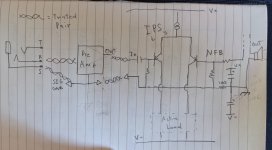
1. Local rail decoupling capacitors need to have ground at star point
2. Speaker return have ground at star point
3. NFB ground should be with signal ground
My main points of confusion:
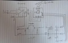
1. In preamp, do I add an additional return path for signal ground to PSU ground on its PCB? Or, do I only allow preamp signal ground to be returned through the main amp unit and its star point? In the picture, there is no connection to signal ground to PSU ground that comes in with supply rails.
2. Is the 100 ohm resistor that separates signal ground and PSU ground at the star point necessary?
"drawing" 😱 is attached, appreciate any feedback/discussion. Thank you!
I wanted to draw it out and see if it made sense to me, and hear if anyone has any suggestions.
My main takeaways are:
1. Local rail decoupling capacitors need to have ground at star point
2. Speaker return have ground at star point
3. NFB ground should be with signal ground
My main points of confusion:
1. In preamp, do I add an additional return path for signal ground to PSU ground on its PCB? Or, do I only allow preamp signal ground to be returned through the main amp unit and its star point? In the picture, there is no connection to signal ground to PSU ground that comes in with supply rails.
2. Is the 100 ohm resistor that separates signal ground and PSU ground at the star point necessary?
"drawing" 😱 is attached, appreciate any feedback/discussion. Thank you!
Attachments
Star grounding usually is applied to medium to high current paths.
The reason is the track/wire has resistance and the currents going through them modulate a voltage in them.
I fell in the trap of many years ago of just laying out a pcb randomly with a pre amp and its power supply. On power up with inputs shorted I was getting 1VAC on the output !
It seems the short charging impulses into the smoothing caps was modulating the ground. This got amplified through the pre amp onto the output.
I re-laid out the pcb keeping power supply separate and only joining grounds at pcb edge connector and this worked great.
Great insight. Thanks for your input, Nigel.Star grounding usually is applied to medium to high current paths.
The reason is the track/wire has resistance and the currents going through them modulate a voltage in them.
I fell in the trap of many years ago of just laying out a pcb randomly with a pre amp and its power supply. On power up with inputs shorted I was getting 1VAC on the output !
It seems the short charging impulses into the smoothing caps was modulating the ground. This got amplified through the pre amp onto the output.
I re-laid out the pcb keeping power supply separate and only joining grounds at pcb edge connector and this worked great.
Once you have a pre-amp in between the source and amp, the star ground is not effective. If I would to redesign, I would star ground at the amp side; where the input ground and pre-amp ground would tie to the speaker return ground.
Which also means my source ground would go to the amp directly, skipping the pre-amp. The pre-amp ground will still connect to the amp.
Which also means my source ground would go to the amp directly, skipping the pre-amp. The pre-amp ground will still connect to the amp.
2. Speaker return have ground at star point
Speaker return has to go back to local rail decouple. Not the star ground.
1. In preamp, do I add an additional return path for signal ground to PSU ground on its PCB? Or, do I only allow preamp signal ground to be returned through the main amp unit and its star point? In the picture, there is no connection to signal ground to PSU ground that comes in with supply rails.
"drawing" 😱 is attached, appreciate any feedback/discussion. Thank you!
Ideally, you only want one star for your ground. However, it is pretty common to have more than one star in your whole system.
Do you put preamp in a separated box with separated power supply? If so, you will have at least one star ground in each box.
You need to join signal ground with power ground at each star ground point.
Last edited:
2. Is the 100 ohm resistor that separates signal ground and PSU ground at the star point necessary?
It is for rf bypass.
As previously mentioned by nigelwright7557.
Do not use big cap to decouple signal ground. It will inject noise from power rail to signal ground.
However, without those caps on signal ground, it is subjected to rf interference. We use a low value resistor to bypass those rf to power ground. At very high frequency, we assume, the inductance of signal ground wire will have more impedance than a 100 ohm resistor.
Okay. This is a point of confusion for me. If the pre amp is in the same box, is there a way to pass signal ground to amp unit while not polluting it? I was wondering if NOT referencing signal ground to PSU ground in the pre amp was an option, and letting the amp unit do this for me, right before the star point. I'm unsure if this is a realistic option.Ideally, you only want one star for your ground. However, it is pretty common to have more than one star in your whole system.
Do you put preamp in a separated box with separated power supply? If so, you will have at least one star ground in each box.
You need to join signal ground with power ground at each star ground point.
Great, thanks.Speaker return has to go back to local rail decouple. Not the star ground.
Of course, that makes so much sense. Thank you.It is for rf bypass.
As previously mentioned by nigelwright7557.
Do not use big cap to decouple signal ground. It will inject noise from power rail to signal ground.
However, without those caps on signal ground, it is subjected to rf interference. We use a low value resistor to bypass those rf to power ground. At very high frequency, we assume, the inductance of signal ground wire will have more impedance than a 100 ohm resistor.
Speaker return should go back to the star, else the distortion may jump up significantly, the star is where the amp's input senses the output voltage. The local decouplers common point should go back to supply ground, not the star ground for the audio path, which should only carry linear audio currents if possible.
The feedback network can only linearize the output if it sees the true output voltage.
Currents through the decoupling caps are non-linear and include PSU noise too, and should never get into the feedback loop. The local decoupling caps are for stability, they are not signal path. This can easily be the difference between 0.001% distortion and 0.01% distortion!!
By the same token the take-off point for the feedback network needs to be from the hot output terminal, not from a random point on the trace joining the emitter resistors (which carries non-linear currents) This is basically another star connection for the amp output, loudspeaker connection and feedback network.
Last edited:
Speaker return needs to go back to the star, else the distortion will jump up significantly, the star is where the amp's input senses the output voltage.
If you put speaker return to the star, you essentially skip decouple cap. In that case, you don't even need decouple cap.
Mark,Speaker return should go back to the star, else the distortion may jump up significantly, the star is where the amp's input senses the output voltage. The local decouplers common point should go back to supply ground, not the star ground for the audio path, which should only carry linear audio currents if possible.
The feedback network can only linearize the output if it sees the true output voltage.
Currents through the decoupling caps are non-linear and include PSU noise too, and should never get into the feedback loop. The local decoupling caps are for stability, they are not signal path. This can easily be the difference between 0.001% distortion and 0.01% distortion!!
By the same token the take-off point for the feedback network needs to be from the hot output terminal, not from a random point on the trace joining the emitter resistors (which carries non-linear currents) This is basically another star connection for the amp output, loudspeaker connection and feedback network.
Thanks for your input. I do remember this from Doug's book as well, something like this, if I'm not mistaken.

Okay. This is a point of confusion for me. If the pre amp is in the same box, is there a way to pass signal ground to amp unit while not polluting it? I was wondering if NOT referencing signal ground to PSU ground in the pre amp was an option, and letting the amp unit do this for me, right before the star point. I'm unsure if this is a realistic option.
Signal wire always should come in pair, + and the ground.
For power board, you can just use the signal ground come from the output of preamp board. Just make sure use relative big gauge wire for ground. It should be fine.
The mechanism that signal ground is polluted is through power amp's feedback resistor. I think it should be fine, unless the feedback resistors are uncommonly small value. You can also run a dedicated ground from the star only for feedback resistor ground.
Okay. This is starting to make sense to me. Last thing though: should I not connect signal ground (on preamp board) to psu ground (on preamp board), in an effort to isolate signal ground from psu ground? Is this impossible to due through op amps in the preamp, since their supplies are referenced to PSU ground?Signal wire always should come in pair, + and the ground.
For power board, you can just use the signal ground come from the output of preamp board. Just make sure use relative big gauge wire for ground. It should be fine.
The mechanism that signal ground is polluted is through power amp's feedback resistor. I think it should be fine, unless the feedback resistors are uncommonly small value. You can also run a dedicated ground from the star only for feedback resistor ground.
should I not connect signal ground (on preamp board) to psu ground (on preamp board), in an effort to isolate signal ground from psu ground?
Signal ground and power ground should only be connected together on the power supply side.
However, I don't think there is much current going on your preamp board. You may go with one ground on preamp board just fine. Note that, treat that ground as signal ground. Do not put any big cap on that ground. Just put couple 0.1u around op-amp chip.
Okay. Here is my latest revision of schematic, I hope I'm getting it.Signal ground and power ground should only be connected together on the power supply side.
However, I don't think there is much current going on your preamp board. You may go with one ground on preamp board just fine. Note that, treat that ground as signal ground. Do not put any big cap on that ground. Just put couple 0.1u around op-amp chip.
1. Star point includes all audio signals - NFB return, SGND return, speaker ground return
2. After star point - rail decoupling caps, this return path to the PSU board with rectifier and larger reservoir caps
3. No large caps on preamp board - only will have 0.1 uF decoupling at supply nodes
4. SGND and GND are connected on preamp board
Does this seem to be about right? Appreciate all your help.
Attachments
Star point should be on power supply board.
I just quick glanced at Doug’s book (not the latest version).
The diagram regarding grounding is good.
Expect one thing, speaker return should be connect to middle point of local decouple, which is near to power amp output transistors. No matter the book says, speaker wires should always come in pair. If not, you essentially create a coil. It is subjected to get interference. It also subjected to emit interference considering the current it can carry.
Last edited:
Star point should be on power supply board.
I just quick glanced at Doug’s book (not the latest version).
The diagram regarding grounding is good.
Expect one thing, speaker return should be connect to middle point of local decouple, which is near to power amp output transistors. No matter the book says, speaker wires should always come in pair. If not, you essentially create a coil. It is subjected to get interference. It also subjected to emit interference considering the current it can carry.
Thank you both for your input. I've gotten to a later stage in the design, and I believe I am able to ask a more direct question. Thank you for the PDFs, very informative.
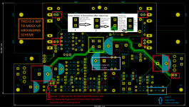
Currently, in the picture below, I have the HBR and other grounds all star pointing at the GND terminal, which returns to the PSU board. I believe this is incorrect, and in the upper middle part of the picture, I have mocked up the way I believe it needs to be and drawn a picture.
FYI: I copied the spade terminal footprint, just to use as a symbolic reference for the different nodes that we are discussing (SGND, 0V relay GND, PWR GND, SPK RETURN), but note that I am not advocating for the use of an entire terminal with an external connector for each node.
What I have tried to convey in my picture:
1. Audio star ground - all HBR and audio ground connections need to meet here (QUESTION: does this include CCS and VAS grounded components, e.g. bootstrap cap from rail to bias point for ccs, or collector of first VAS transistor in EF VAS(this without Q18) topology?)
2. Audio star ground goes to Misc ground - this ground is used for relays and other components that need it for biasing, but no heavy currents through here
3. Misc ground goes to PWR ground - this ground is where the rail decoupling capacitors (big and small) connect, and this is directly connected to the PSU connector which returns GND to the PSU board.
4. Spk return to PWR ground - speaker return is placed very near the PWR ground terminal and is connected to it as well.
I hope this isn't too convoluted, if there are any thoughts, please don't hesitate to comment. I've been learning a lot through this process, so thank you very much.
Attachments
Last edited:
Do you not realize amps have a great big multi-turn coil on the speaker output anyway for stability driving capacitive loads?Star point should be on power supply board.
I just quick glanced at Doug’s book (not the latest version).
The diagram regarding grounding is good.
Expect one thing, speaker return should be connect to middle point of local decouple, which is near to power amp output transistors. No matter the book says, speaker wires should always come in pair. If not, you essentially create a coil. It is subjected to get interference. It also subjected to emit interference considering the current it can carry.
I don't see how you worrying about loop area has anything to do with connecting to the middle of local decouplers anyway. Keep those non-linear currents out of the star ground!! Minimizing loop area is great, but you care in sighting the output inductor is probably more important for inductive cross-talk.
I don't see how you worrying about loop area has anything to do with connecting to the middle of local decouplers anyway.
I agree with you on this part.
The analogy of "loop area" explanation does not reflect the whole picture of the issue of speaker ground wire. However, I find it is more acceptable to the "major" audience.
Here is the core of this issue, if you draw a circle around the power amp board, the sum of currents flowing into that circle is equal to the sum of currents flowing out of that circle. See explanation of Kirchhoff's circuit laws. Kirchhoff's circuit laws - Wikipedia
Assume you put speaker ground return to the star point, which is on the power supply board outside the circle you drew. However based on Kirchhoff's law, the total sum of current across the circle of the amp board must be zero. The speaker return current could not disappear. In a big chance, the return current still goes through the power-ground wire of amp board.
There is always a speaker return current that need go back to amp board, no matter where you physically connect the speaker return. Put the speaker return to the star point outside the amp board, you just make the issue even more complicated. It is counter intuitive, that's why I use "loop area" analogy to explain at the first place.
Last edited:
- Home
- Amplifiers
- Solid State
- Signal Ground Question