Please review my cart before I order parts for my PSU!

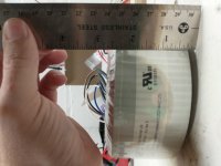
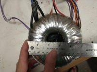
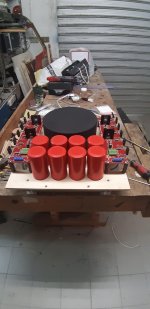
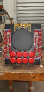
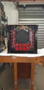
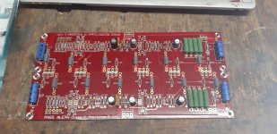
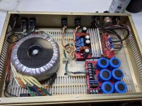
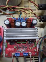
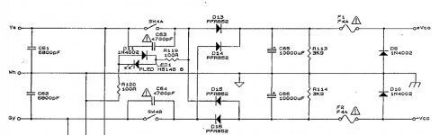
My plan is to build diyA PSU with monolithic rectifiers and a 600VA 24v transformer.

I think this Mouser cart contains everything I need, minus the transformer and PCB. Please let me know if anything looks off or if I seem to be totally off the rails on my assumptions what I need 😛

Direct cart link: https://www.mouser.com/ProjectManager/ProjectDetail.aspx?AccessID=37d2997a84

Scroll "code" section to the right to see quantities and prices

Code:
[FONT="Courier New"][B]Part Number[/B]        | [B]Brand[/B]              | [B]Description[/B]                                                             | [B]Quantity[/B] | [B]Price[/B] | [B]Total[/B]
CL-60              | Amphenol           | Inrush Current Limiters 5A 10ohm Straight leads                         | 3        | $2.06 | $6.18
SLPX183M050H9P3    | Cornell Dubilier   | Aluminum Electrolytic Capacitors - Snap In 18000uF 50V 20% 85C          | 8        | $5.95 | $47.60
KBPC5010-G         | Comchip Technology | Bridge Rectifiers DIODE RECT BRIDGE 50A 1000V                           | 2        | $3.61 | $7.22
CPF322K000FKB14    | Vishay             | Metal Film Resistors - Through Hole 3watts 22Kohms 1%                   | 2        | $1.27 | $2.54
CPF31R0000FKE14    | Vishay             | Metal Film Resistors - Through Hole 3watts 1ohms 1% 100ppm              | 2        | $1.15 | $2.30
TLHG6400           | Vishay             | Standard LEDs - Through Hole Green Tint Diffused                        | 2        | $0.46 | $0.92
CPF3R47000JNB14    | Vishay             | Metal Film Resistors - Through Hole 3watts .47ohms 5%                   | 8        | $1.86 | $14.88
CCF0710K0JKE36     | Vishay             | Metal Film Resistors - Through Hole 1/4watt 10Kohms 5% Rated to 1/2watt | 2        | $0.13 | $0.26
1985852            | Phoenix Contact    | Fixed Terminal Blocks MKDSN 1.5/3 HT                                    | 2        | $1.64 | $6.56
62409-1            | TE Connectivity    | Terminals .250 PCB TAB                                                  | 8        | $0.14 | $1.20
MKP2D031001F00JO00 | WIMA               | Film Capacitors 0.1uF 100 Volts 5%                                      | 2        | $0.66 | $1.32

[B]Total $91.06[/B]
[/FONT]

Anyone built a PP-1C or PP-2C (Alan Wright designs)?

Hi,

I was looking the PP1 design at Schematics and I've also read about and found scematics for a newer KT88 based revision called PP-2C

I've seen threads here from people who were contemplating to build one of those but I have not found any actual stories of completed builds so far.

Did anyone here or someone you know build one of these and would be willing to share some expiriences, stories or pictures? That would be very interesting...

Cheers!
Lars

Does a high end capacitor on woofer improve sound?

To start I'm building a 3-way speaker using these drivers:

Tweeter: Sb Acoustics satori tw29txn-b
Midwoofer: Sb Acoustics satori mw13tx
Woofer: Sb Scoustics satori Wo24p

I've been going down the rabbit hole of how certain crossover parts could alter a speakers sound signature. My interest Is if anyone has observed a noticable change in sound by using different types/brands for a given crossover filter.

More specifically if a 2nd order low pass was used would using a high end capacitor but "worth" two, three, or more times the cost

PC speaker project

Hi,

Firstly I want to be clear that I am a complete novice with circuitry and electronics. I do have a healthy respect for electricity, and safety is always on my mind.

I had a mad idea to free up my Bose bluetooth speaker I've been using with my home pc so I can take the Bose back downstairs where it should live. I have some old Dell pc speakers but they're no longer working so I mused about how to replace them. I came across some old Hi-Fi speakers that would work well in my office, but being passive they'll need an amp.

The mad idea: I had an old Panasonic LCD TV ready for scrapping, and I thought "Why not take the amp and power supply out and make it into a speaker amp?"

That started me off, so I've now cannibalised the TV, and taken the boards out. I have the TV's service manual downloaded which tells me what the parts are.

So the issues I need to consider:

I'll need to create a line input, but the more I think about this the more I realise my knowledge limitations.

The TV volume would obviously be controlled by remote. I have also taken out the IR receiver, so could this circuit be used with a volume control?

Housing the amp. Is a wooden box suitable?

I'm not after anything high quality - that could be worked on once I have more experience, just something to listen to music whilst on the pc. I don't want to spend loads of money buying kits, I just want to learn how to do this and gain some satisfaction knowing I built it myself, with help obviously!

Apologies for the long initial post, and any pointers or advice to "Get out before you do major harm to yourself and your family" will be gratefully received.

  • Locked
XRK Imposters on AliExpress

Hi Folks,
It seems there are several products popping up on AliExpress under the “XRK” brand. It’s kind of flattering and funny, but a bit worrisome because I don’t know what they sound like or how good they are. Even the logo looks a bit similar. Maybe it’s pure coincidence? I don’t know.

Anyhow, just wanted to let you know that I had nothing to do with these products being offered in this way.

HTB1e5fdPVXXXXa6XVXXq6xXFXXXZ.jpg_640x640Q90.jpg_.webp

XRK E3 Mini Desktop Earphone Headphone Amplifier HIFI Digital Stereo Audio MP3 Amp with LME49600|mp3 amp|amplifier hifiheadphone amplifier hifi - AliExpress

There are more…

HTB11V6IboLrK1Rjy1zbq6AenFXay.jpg_640x640Q90.jpg_.webp

https://m.aliexpress.com/i/32977079729.html

HTB10qv5bjDuK1Rjy1zjq6zraFXaz.jpg_640x640Q90.jpg_.webp

https://m.aliexpress.com/item/32975...2g0n.store_m_home.smartJustForYou_830115793.0

HTB1MkRDPFXXXXbLXXXXq6xXFXXXs.jpg_640x640Q90.jpg_.webp

https://m.aliexpress.com/item/32794...2g0n.store_m_home.smartJustForYou_830115793.0

NAD transformer config for new Wolverine?

Advice needed - NAD transformer config for new Wolverine?

I am gathering parts to build the upcoming Wolverine and found a broken NAD t773 as a chassis and heatsink donor.

Trying to figure out if I transformers as well, and if so what configuration makes sense. Unfortunately I don't know the VAC on them.

The t773 is a 7x110, with 2 transformers. One runs 3x110 and some extras, one runs 4x110. Curiously, the larger 4x110 runs at 54-0-54v, the smaller at 51-0-51. They must drop a decent amount of voltage as power supply is just under 60 VDC.

Here are the options as I see:

1) use the 4x110 only. I think NADs ratings are a bit conservative and it was capable of higher peak power, so 2x200 seems reasonable.

2) use the two transformers as dual mono. As I understand the different voltage would only effect max potential output and I won't be near there.

3) scrap and get an appropriate, lower voltage transformer recommended for the build.


Note this amp will be driving 4-ohm speakers, though never at high volume.


Any advice on this one?

4x110 - 5 3/8" x 2 1/2"
3x110 - 5 1/8" x 2 1/2"

Attachments

  • IMG_20210804_073610188.jpg
    IMG_20210804_073610188.jpg
    608.2 KB · Views: 269
  • IMG_20210804_073622163.jpg
    IMG_20210804_073622163.jpg
    508.9 KB · Views: 249
  • IMG_20210804_073633973.jpg
    IMG_20210804_073633973.jpg
    650.2 KB · Views: 249

Maya R2R Advanced Volume controller

I still get emails from people interested in Maya, so here we go. Same prices as on the first GB.

Features:
- R-2R 64 1dB step attenuation
- Android/IOS client for remote control
- infrared remote RC5 protocol with autolearning
- infrared remote NEC protocol for Apple remote (default)
- OLED display
- 4 selectable inputs
- independent volume control for each input - very good for A-B source comparison
- extra low noise ground separation between digital and analog circuitry
- inrush current protection
- soft start with speaker protection
- soft turn off with speaker protection
- plate voltage delay for tube pre/amplifiers
- temperature display and monitoring
- temperature protection
- serial I2C bus for unlimited channel extension
- easy direct control and setup with precision optical encoder

Current firmware version is 0.9

More detailed information about Maya is available at vicol audio : MAYA - your ultimate volume-controller
An implementation from first GB Interest check on Vicol Audio Maya R2R Volume controller - Page 12 - diyAudio


Regards,
Tibi

Class A? Really?

I've never been that interested in class A, the low power output, expensive ancillaries, static power consumption and roasting heat put me off.

This little unit looks quite promising for the active 3 way set up I have in mind though. 30 watts is juuuust enough, it's appealingly simple, and it's pleasingly chap. Also claims to be pretty robust and heat proof. Does it look OK to you?

It quotes perfectly acceptable distortion at 10w. Hmmm. Does that mean that, realistically, it's a 10w amp? 30 is tight, 10 is a non starter.

Assemble A30 FET Pure Class A Power Amplifier Board Stereo HiFi Audio Amp Board | eBay

Description:

The A30 power amplifier circuit is very compact. It consists of only 8 transistors and a few passive components in a single channel. There are no redundant components, which is in line with the HiFi concept of “simply supreme”.
The A30 power amplifier circuit is very stable. It can use a relatively small heat sink and the current is very large. When the heat sink temperature is 80 °C, the circuit can work very stably. There is no need to worry about overheating and damaging the transistor.
A30 installation and commissioning is very simple, only need to connect DC power, adjust the quiescent current and midpoint potential is OK. Where R17 regulates the midpoint potential and R16 regulates the quiescent current.
The A30's low cost and small size of the power amplifier board make it ideal for small HIFI or desktop amplifiers and multichannel amplifiers.
This project consists of two boards (two channels. one board = one channel)
Specifications:
Maximum output power: 30W/8 ohms 60W/4 ohms
Maximum Class A power: 30W
Maximum supply voltage: DC+ -33V
Harmonic distortion: <0.01% 10W/8 ohms
Frequency response: 0Hz-100KHz
Damping coefficient: >100
Signal to noise ratio: >96dB
Conversion rate: >30V/uS
Input sensitivity: 0.5V (effective value)
Input impedance: 10K
Gain: 31dB (34 times)
Size: 99mm × 53mm (mono PCB size)

Onkyo NS-6130 streamer with Amazon Music

Hi, I know this isn't really "DIY", but has anyone set up a Onkyo NS-6130 streamer with Amazon Music (Unlimited)? I am only getting files at 256kbps rather then HD/Ultra HD (as Amazon calls High Res). This happens using The Onkyo App (Android) and the Amazon Music App (Android + Windows 10). Amazon say you should see “HD/Ultra HD flags” to change the quality. I have not seen that on the Onkyo or Amazon App. I have FLACs on my media server, they play fine (both Streamer + Amp are capable). The Onkyo is connected to my Network by Ethernet cable and I have Fibre broadband. Has anyone else had this problem with Amazon music? Any advice appreciated……

My Aleph 5....italian style 2

I wanted to share with you some photos of the construction of my version of Aleph5.
after endless searches to find the right components and many hours of work this baby was born.
sounds divinely .... thanks mr. PASS.
what do you think?
how did it come?

I apologize for my bad english

Attachments

  • 20210915_192734_gsModify.jpg
    20210915_192734_gsModify.jpg
    306.2 KB · Views: 358
  • 20210912_164249_gsModify.jpg
    20210912_164249_gsModify.jpg
    983.9 KB · Views: 346
  • 20210915_130422_gsModify_gsModify.jpg
    20210915_130422_gsModify_gsModify.jpg
    951.1 KB · Views: 345
  • 20210824_130847.jpg
    20210824_130847.jpg
    1 MB · Views: 339
  • 20210823_111957.jpg
    20210823_111957.jpg
    326.3 KB · Views: 340
  • 20210824_131220.jpg
    20210824_131220.jpg
    463.7 KB · Views: 284
  • 20210919_091351_gsModify.jpg
    20210919_091351_gsModify.jpg
    375.6 KB · Views: 269
  • 20210724_180332.jpg
    20210724_180332.jpg
    1,018.1 KB · Views: 280

What to use for replacing axial electrolytic caps?

In amplifiers, not speakers. Some amps used axial electrolytics.

Axial? Do axial caps exist in low leakage, nonpolar, or "audio grade"? What are some capacitor brands/models that are good for amplifier use?

Radial with the legs spread wide? It seems like this would be less rigid mechanically and more susceptible to vibration than the original axial caps :scratch:

in shock at how amazing my tiny cheap 2.1 system sounds with TPA3116D2 pcb

I posted earlier about perhaps making some diy speakers as I was not happy with the sound from my bass face SPLBOX.4BL plastic speakers that cost me £9 with delivery (dunno how they do it sometimes lol was on sale). Had muffled highs and mids and a lot of distortion..

BUT I ws using this cheap crappy amp! 12V 2.1Channels 400 WATTS Car Audio Stereo Amplifier MP3 Radio Booster HiFi H6 | eBay

Then I upgraded the amplifier and omg it sound 100 times better never had a TPA3116D2 based amp before. I am driving a Panasonic subwoofer rated at 180w (prob more like 100). The two satellites are 50w each.. Basically its all perfectly matched for the amp ! Lucky me! (amp is 50w x 2 and 100w sub)

2.1 amplifier I got £17 hahah!!
BLUETOOTH HIFI POWER SUBWOOFER 2.1 CHANNEL STEREO AUDIO AMPLIFIER BOARD TPA3116 | eBay

TPA3116D2 chipset in a amp with Bluetooth I haven't even put an enclosure around it haah.

Based on that chipset.
TPA3116D2 data sheet, product information and support | TI.com

I tell you what for a set up that cost me about £26! It is great! I got the sub woofer free from family that were throwing it out, been left outside in a garden for months or years even lol Still sounds pretty clean! I reckon on ebay its so easy to find a sub nearby for cheap a hifi sub or one from a 5.1 set up..

I am amazed at the detail I am now getting from this cheap diy set up! Instead of dead highs and lacking details its actually quite a cutting sound delivering a pretty balanced clear sound of all frequencies Right down to 30hz-40 (i guess)..

Basically I have a three way set up now (2xtweeters 2xmids 1xsub) and never had that before.. Nice to feel so immersed in the sound! Having the higher frequencies physically higher in the space and sub from the ground it adds a certain immersion to the sound. I am just not used to it as I always mixed and listened to music on a two way stereo set up. I live in a tiny space so I knew to get a nice full sound I would have to opt for 2.1 to get a full range sound. Speakers have only 3 inch mid drivers and 1 high. Also they have screws on top and bottom for great outing ideas in a small space, currently simply using the supplied brace / holder as a stand for my tiny desk at the least the speakers are facing my head!

PICS OF MY MICRO SET UP!
amplifier 2.1 examples - Google Drive

Bassface SPLBOX.4BL
SPLBOX.4BL 4Ohm Waterproof Mini Box Speaker Pair 100w RMS Blue


Really fun for playing computer games on my ps2 emulator, watching movies and I will very much enjoy making music and editing video, I can tell already! And its clear enough for a basic monitoring situation kinda has a PA sound to it, like I have a micro PA on my desk it goes LOUD! 😉 Can see a house party vibe in the future for sure!

Really I love making these DIY set ups fitting around the space and budget and I am always amazed at the quality we can achieve at such low cost! Through upcycling, investigating, learning and luck! great thing is I know I can think about one day upgrading my two satellite speakers or any part of the set up.. Maybe make a DIY sub woofer.. Great hobby and really made my listening experience a totally different one, worth every minute and penny to get it right!

Rockling out to this its amazing stoner rock feeling that bass on my sub 🙂 Good set up for bassy doomy metal rock:
https://youtu.be/1HM6J_xNO3I

After sales service

For any of you who haven't had the need to call on it, Hugh is magnificent when it comes to helping out in cases where for any reason, you might have a problem with one of the many products he's created over the years. For me, the problem was self induced, so it's extra good of Hugh to help me through with his email trouble shooting system

16 years on and my AKSA 55N+/GK-1 combination is still working perfectly, in harmony with my fairly efficient [96db] DIY speakers from the same time. I did have a small incident late last year, after having to uproot the whole system to escape from the bushfires that ravaged our east coast forests and their residents both human and animal.

The Incident: I post this because it might help somebody else. Many RCA sockets, that are fitted to cases, depend entirely on friction to keep them from rotating when you remove/replace a cable from them. Simple enough in a way but given there's no specified torque, or toque wrench, to give you the right tension on the retaining nuts and that squashing a nylon washer doesn't give you much feel for the correct tension, these things can slip/rotate. For me, this happened when I removed some cables that hadn't been touched for maybe 20 years [and were tight]. When I re-installed the cables, the RCA terminal was loose so the ground ring was also loose, so the connection caused problems.

Now, I'm using a dab of loctite plus the more mundane and obvious strategy of checking the RCAs more carefully while removing/replacing cables.

Thanks again Hugh.

Jules

Refinishing ADS Speaker cabinets

I recently found a pair of ADS 1290 in fair cosmetic condition, but sound amazing. Well worth restoring, methinks.
As found, the color and grain looked anything but walnut, but as the picture shows, a few minutes to remove the varnish and 30 years of discoloration, then
one application of boiled linseed oil makes a huge difference.
Anyone on the fence about spending lots of time, care and elbow grease to do the same should be encouraged.
Peter

Attachments

  • B7108EB3-D0A4-4B29-86DD-771618004349.jpg
    B7108EB3-D0A4-4B29-86DD-771618004349.jpg
    655.8 KB · Views: 109

Phase Linear 700B burns speakers

I am new to the forum, I don't have much electronic expertise but have been an avid hifi fan most of my life.

I bought my PL 700B twenty years ago and it had been in storage since 1980. It had been checked over and had a clean bill of health and sounded brilliant.

After running it for a few months it sent some feedback down one of the channels and burned out a speaker.

I went to the best technician I could find and after 3 tries and many components replaced it still had the problem. It was still frying speakers, most of the time it worked fine but if the feedback hit it was too late for the speaker. He said he didn't know what the problem was and his only suggestion was to replace all the components inside. I gave up parked it up, I hated frying my beautiful speakers.

Being in Sydney, Australia I didn't have a lot of options as far as getting it repaired. They are rare out here so finding someone with the necessary expertise is difficult.

I would like to get it repaired properly but want to be armed with a bit of info before I give it to someone.

I was hoping that someone had encountered this problem before and could point me in the right direction.

Thanks in advance
Peter

Problem using Hammond 126C IST

Hello friends. I recently bought a pair of Hammond 126C interstage transformers to couple my 6SN7/300B SET. Using the circuit attached, I am getting 63 Volts RMS drive for the 300Bs with a very clean looking waveform down to 40 Hz. This is way more than adequate for the 300B. My problem is that I am getting an ugly waveform on the amplifier output, which is originating in the 6SN7 driver stage. (I have proven the source by experimentation). The offending signal is about 15 millivolts P-P at 50Hz with a strong 3rd harmonic component. My line frequency is 50Hz, so I am tempted to think it is mains supply pickup. This ugly beast was not present in the output when I was using RC coupling. Has anyone else experienced this problem with the 126C? I'd very much appreciate any suggestions. Waveform.jpg

Interstage 1.png

'Distortion separation/crosstalk' between channels?

I have been modifying (and hopefully improving) some basic amps for fun lately. One was a Yamaha RS300 and a Rotel RA 930-AX(for a friend). Main improvement on both was increasing bias to abt 30mV between emitters. Anyway, that is not the topic here.

In these cases I wanted to measure channel separation, witch I have not done much, since many of my DIY builds have been dual mono, and maybe I have not considered it to be a significant factor for SQ.

What I found was that separation was pretty bad on both amps, especially on higher frequencies (around 40dB from memory).
However, the most shocking to me was that the 'distortion separation' was abt 0!? What I mean is that the distortion components on the silent channel were about the same level as the distortion components on the driven channel, even if the fundamental was 40-60dB lower. This was almost the same on both of these amps.

I suspect it has to do with the common PS, and possibly that the front end is on the same rails as the output stage?

Could somebody explain this further?

The Magnepan Tympani 1D Ribbon Project

Hello there! I am a happy owner of a set of Magneplanar Tympani 1D speakers. I have rewired all 4 of the bass panels and have been pleased with how they sound. However, I have a large problem, one of the tweeters in them was destroyed (and I mean destroyed) at some point in their life to the point where the magnets and frame were damaged. It was a goner, and apparently Magneplanar no longer makes the tweeters anymore and so you can probably guess how I feel about that situation...

Anyway.

I have read a large amount of threads on this section discussing DIY ribbon tweeters. I am new to this website so please excuse my ignorance, but if anyone here has any guidance or threads discussing long ribbons, please link me to them as I need to read as much as I can before getting into this.

Efficiency is not a big deal here as from what I can tell that is the subject of concern for most. The bass panels are 84db 1 watt according to the Tympani 1D manual. What kind of magnet setup would I need to achieve that level of efficiency? I am aware that it is dependent on the size of the ribbon itself but any ballpark figures would be appreciative.

I am also thinking of doing a large scale tweeter, say 3" in width. I am looking for any opinions on whether or not a 3" wide ribbon tweeter would be able to go from 200hz to 20khz. I know the original tweeters crossed at 1.2khz but I'd like to take that down to delegate the bass panels to strictly bass, or close to that anyway.

I have a bit of experience and I'm good with rewiring a toroidal or traditional transformer for my needs, so for me that's not much of a concern.

Any links, information, or ideas would be excellent to be presented here. Question, has anyone ever tried using NiChrome foil for a ribbon diaphragm? I appreciate any replies, I really want to get these excellent speakers going. Thank you.

Out of the closet -Hi from the Netherlands

Dear fellow enthousiasts,

Via this post I would like to introduce myself 🙂 Music and audio has kept my interest all my life and in the course of time I build a small number of systems by my own design.

As a hobby musician, I played the bass in a number of local bands and it was great fun back then. Audio and making music myself were two sides of the same coin to me. As I became familiar with the sound of (amplified) instruments and drums and saxophones and trumpets and keyboards, I wanted to be able to recreate that experience at home. In the nineties, I watched, listened to and enjoyed great (and sometimes not so great) horn stacks in pop venues and discotheques. So I started to experiment with diy horn speakers, because I wanted that dynamic, crisp and focused sound at home too.

Because internet did not exist back then, I went to the library to study the sparse books available about audio design, I bought diy magazines and read about the many aspects that influence audio reproduction.

From my unavoidably limited knowledge, I started to build a horn system that has been modified over time, when new knowledge (and especially more purchasing power) became available. So over the course of some 25 years, I ended up with the system that is depicted in the photograph. I guess it will never be finished, but at the present state, I am very satisfied with the sound. My (mid)bass horns have never been replaced and in use for more than 25 years. Lucky shot I guess...

I would like to thank all contributors on this website, I have learned a lot! Some day I hope I will be able to start a small business (yet another one 😀) doing (horn)loudspeakers and tube amps for the local market.

I may contribute once in a while on a topic, but my academic knowledge of the matter is not that great. I hope I will be able to share some of my insights that I have picked up along the way, and post some pictures of my gear " to show off 😉".

Attachments

  • Mijn installatie_800x400.jpg
    Mijn installatie_800x400.jpg
    38.4 KB · Views: 142

Horns or waveguides for 1” compression drivers

I have tried to source 1” horn or waveguide but haven’t found none in production or sale. Also European source preffered.

Looking for B-52 PHRN-1014, QSC PL-000446-GP or similar 90° x 60° waveguide.

Best compromise that I have found is 18Sound XT1086 but prefer lower crossover point than ~1,5kHz so larger waveguide like QSC would be better.

Any ideas or solution to this?

Raspberry pi + IQ audio DAQ pro

I tested this. (IQ audio Dac Pro) It has a clear, clean sound.

Unfortunately The treble (ie >2kHz) is piercing and sharp, and it makes me think this DAC does not have a flat response.

I much prefer the sound-card of the old laptop.


With the Same Amp and speaker setup:


When comparing to my laptop sound card (no effects or equalisation enabled)
with the IQAudio DAC pro+ on a Rapbserry pi 3..

The difference was obvious,
The High tones were piercing, female vocals and cymbals were unpleasant and sharp. Things only sounded normal after dialing down the treble on the amp. What detail am I missing out on now.. ?, by cutting down a chunk of sound with the dial.

With the old laptop setup, the Amp equalisation settings can be at dead-centre, and the sound is 'balanced' and full.


I thought I would share my encounter, has anyone else found similar ?

Dangerous Ampex Preamp!!!

Hi Everyone,

Someone has asked me to recap this vintage Ampex 600 tape machine preamp.

Before turning it on I was trying to trace out the internals and relate the insides to the schematic and noticed some weird extra stuff in one corner! The signal in off the mic seems to be hook directly to the high DC voltage rail! When I tested pin 2 of the XLR socket it read 319VDC!!!

Here is the vid I made which shows the additional components ...

Ampex preamp safety issue - YouTube
They don't seem to make any sense at all!

The original schematic is attached.

Does anyone have any idea why these extra components were added? What they were trying to do? It's strange because none of it looks like newly added stuff (the extra caps and resistors look as old as the rest of it).

Cheers

Tom, UK

Attachments

  • Ampex_600-8.gif
    Ampex_600-8.gif
    130 KB · Views: 646

New to FLAC files, need advice

In the interests of researching newer formats I have ... how can I say this delicately ... "acquired" a number of FLAC files. I can burn these to a CD using standard burning software and they play fine in my Oppo UDP-203 player.

The problem comes about when the files exceed the size of a standard CD. I have tried burning the FLAC files as audio files to a DVD but my burning software (BurnAware) won't allow that, telling me to insert a CD. D'oh! I can also save them to a DVD as data files and use the TV as a menu to play them, but the playback is mighty weird. Specifically, the two channels are out of time with each other, which gives an odd pulsating/echo effect and is very unpleasant. So, I made a few drink coasters so far. 🙂

I'm guessing that FLAC files store the data in chunks rather than interleaving them, but whatever it does this only seems to be an issue with the files large enough to need a DVD. i.e. 24/96 and 24/192 formats. I have tried to convert them to WAV format but have been unsuccessful so far, and in fact I'm unsure if WAV even supports such high resolution.

1. Any suggestions for a PC user (not Mac, not Linux) gratefully accepted. Preferrably not commercial software since this is of idle interest only.
2. It would also be nice to know what I'm supposed to do with DFF files, which also seem to be available. I've never heard of that format.

Edit: I forgot to mention that the files play fine using VLC media player, so they're not faulty. I also tried using a USB stick in the UDP-203 and got the same problem so it's not specific to the disc itself. The UDP-203 is supposed to be able to play FLAC files but it maybe it has issues with high-res formats. Insufficient buffering?

Lateral Mosfets Double Die TO-3 ESP P101

I want to build a mosfet amplifier (maybe the ESP P101) utilizing the transformer and heatsink assembly from a retired Tandberg 3012 integrated amp. The Tandberg was rated at 100W rms at 8 ohms / Ch.
The transformer secondary supplies about 57VDC +/- after smoothing to the rails. The original heatsink was quite robust with one pair of complementary mosfet outputs per channel. The original outputs were 2sj55 and 2sk175 rated at (ID) 8A and 125W ea. Tandberg seemed to think that these ratings were adequate for the 57V rails and functioned till the end without failure. Rod Elliot (ESP) seems to take a much more conservative approach with these higher rails (57V) and strongly suggests doubling up on the complementary pairs. As you can see in the pic the Tandberg heatsink assy. provides only for 2 TO-3 outputs per channel.
ESP P101 amplifier.
Rod recommends the Exicon ECX10N20 and ECX10P20 for the low power output. For my application (at the higher rail) I am considering the Exicon double die TO-3 versions, ECF20N20 and ECF20P20. I have read the pros and cons about the double die versions and still wonder if there are valid points to not using them. If it’s on the internet, it must be valid!?
Can I basically use the double die versions to replace the dual complementary lateral outputs without any real change to the P101 driver circuit at +/- 57VDC.
I emailed Rod and did not get a response.
OR… should I take the chance and use the lower power rated Exicons and justify it by what Tandberg used for power rated outputs. Seems to me that if this amp is used well below its rated output (like in my apartment), I should be able to get away with using the lower rated lateral outputs.

Attachments

  • IMG_0033.jpg
    IMG_0033.jpg
    721.2 KB · Views: 1,417

Tube Buffer Preamp Design

Hey guys, one of my next projects will be a new buffer line stage. The preamp I built a while back using 12AU7s sounds good enough, and for some things it is ideal. But it has too much gain. I am finding that many modern sources (like my DAC or an audio interface) have an output more than sufficient (by a fair bit) to drive an amplifier. With my current preamp (and it is by no means a high-gain design), I have the volume set at about 10% to achieve a normal listening level.

While it would seem that having a simple pot-in-a-box (passive) line stage would be the best, I do have some amplifiers (some of my big solid state amps, for example) have a pretty low input impedance, and while a tube line stage will add distortion, I find that even a low distortion design like my current preamp can take the slightly harsh edge off digital sources (all subjective and subtle). Beyond that, a passive preamp is rather dull and unexciting.

While I will use whatever transformers I have on hand, I think it would be good to design this to be cost effective using off-the-shelf parts in order to make it more beginner friendly. When I was looking for my first project (about nine months ago... I'm not a "seasoned veteran" by any means), I was continually frustrated by the number of designs using rare or difficult to obtain parts.

Enough rambling. I am thinking of doing a very simple cathode follower with a regulated power supply and possibly a constant current source. I've modeled some simple cathode followers in LTspice (just learning how to use it... whole new world of opportunities), and the 6DJ8, 12BH7, 6SN7 and 12AY7 seemed to perform fairly well. I have not modeled these with a CCS. The 12AU7 did not seem to perform quite as well.

As a side note, I think I have a pair of Jensen JT-11-FLCF transformers to use for a balanced output. These would be easy to omit, however, if someone wanted to save the $80 a pair of these would cost, especially if they didn't regularly use it with balanced-input power amplifiers.

My thinking, based off of inexpensive and obtainable transformers let's look at a B+ of around 260-300 volts.

So here's my real question for you all. What tubes do you all like for a cathode follower?

Ideas and suggestions are appreciated.

Thanks and sorry for the long post,

H713

Tri-Amping : Equivalent power query. BS or not too much BS

It's a genuine query as I've got my set-up now and I've been told that when Bi-amping / Tri-Amping you get a synergy that gives apparent power that seems as if you have a much more powerful single amplifier.
Back story there; as way back when I was drooling over the monster Rotel RB 1090 and the sales person was telling me to Bi-Amp and use two much smaller Rotel RB 1070's which would actually have more "Music Power" and said sales man was saying double the actual music power of the 1090 and at a much more affordable price

So my current Tr-amp set-up is 380W into 4R + 150w into 8R plus 150w into 8R
Which is a bit crazy as I'll probably normally use about 15 to 30 watts when listening at a reasonable level
I suppose 680 watts per channel RMS is a tiny bit of overkill but if comparing it to a single amplifier do I really have the equal of a thousand watts per channel??

For those interested
Cambridge Audio Azure [ rebuilt]
Behringer DCX
Jaycar Playmaster / BASS
Rotel RB1070 / Mid-bass
Kenwood L-07M / Mid/tweeter

Into
BASS
Cerwin Vega Vega124
Midbass
Vifa P26
Midrange / Tweeter
Vifa P13 / Vifa D-27
Midrange/Tweeter

How often should transformers blow

Hi everyone, I have a pair of Adam A7 active studio monitors that are about 12 years-old (and an Adam Sub8, which is a little newer) that I intend to keep.

About five years ago, the power transformer in one of them blew, and I replaced it with a transformer from Adam. In the past few months, the transformer in the other monitor blew and I replaced with a new full amp board from Adam (no individual transformers left).

I believe they are running low on replacement parts for these monitors, and I'm debating whether I should buy another amp board (for about £125) in case I have another problem.

Basically, the question is do you tend to find that there are just bad batches or transformers, or is it reasonable for them to blow every 5-10 years?

One other thing worth mentioning--the volume has recently starting fading in and out a little on the monitor that I fixed five years ago. However, I fortunately have a spare amp board now that presumably works fine except for the blown transformer.

Thanks.

KEF B139 Bass Driver SP1212 and SP2055A Crossovers

KEF B139 SP1212 in good, working condition: $50.
(Also have another one with open VC and dented cone which can be included for free with purchase of the good one if you want it.)

KEF SP2055A 3-way crossovers, complete: $50/pair.

Prefer local sale in Los Angeles.

Attachments

  • k8e.jpg
    k8e.jpg
    694.1 KB · Views: 101
  • k8c.jpg
    k8c.jpg
    740.1 KB · Views: 108
  • k8b.jpg
    k8b.jpg
    822.9 KB · Views: 99

Type 42 single ended ideas

I picked up a couple Type 42 tubes from a lot this weekend. They look so classic that I want to build a single ended very vintage hi-fi (yes, I some may think this is a mis-use of the word) amp around them. I know I won't get much power and there's lots of talk about distortion, but I think I could work around it and be happy with the results.

Because part of the attraction is the "look" I want to stay with a 2 digit 6 pin driver. What is everyone's thoughts for a driver. To my uninformed search, it seems a type 76 is what I should target.

Thoughts?

If anyone has a schematic that would be nice also.

Thanks in advance.

Common Grid MOSFET Power Booster

I'd like to build a power booster for a low watt tube guitar amplifier that I recently built. The guitar amp produces about .5 watt sine and maybe 1 watt max. Great for practicing at home.

I saw a design for a power booster using tubes but only achieves a power gain of about 6. I'd like something more in the range of 60 - 100 to get me to 30 - 60 watts for playing out. Using some less common tubes it could be achievable but I like to stick to stuff that readily available.

Ideally, the booster doesn't change the dynamic interaction between the speaker and the tube amp's output section.

Mosfets are maybe a better choice for the application? This is an area I where I'm seriously lacking experience.

Would a common grid setup like this have a chance of working?

Attachments

  • mosfet power booster.jpg
    mosfet power booster.jpg
    114 KB · Views: 199
  • kuehnel-garage-amp.gif
    kuehnel-garage-amp.gif
    27 KB · Views: 189

UcD-18ohg x4, SDS-470, Audiofire12, XLS2000, Fuhrman PS-8RII

So I've finally accepted that I no longer have the time/drive for audio so I'm selling my stack. Crown XLS2000, Echo Audiofire12, Fuhrman PS-8RII power conditioner/delay powerup, 4 channel DIY Hypex UcD-180hg, and 2 channel diy Class D Audio SDS-470.

Hypex 4 channel: ucd-180hg x4 modules with gain resistor removed (great for high eff!) and Hypex SMPS. XLR in for each channel and speaker out is 2x 4pole Speakon. Powercon in/out for power and a power switch on front panel. Setup for rack mount only no feet but I think I drilled the enclosure for feet. Last used in 2018. Powers up.

Class D SDS-470: 2 channel module with Class D torroidal power supply. XLR in for each channel. Has stereo gain pot as well as separate trim pots for each channel. 2 pole Speakon speaker out. Powercon in/out with power switch on front. Also setup for rack mount only same deal with the feet. Last used in 2018. Powers up.

Audiofire12, XLS2000, and Furhman were from same system. Last used in 2018. All power up.

Will include diy TRS to XLR for all channels, diy Powercon cables, and a pile of 8 pole cable, 8/4/2 poles Speakons, and maybe more.

$600 takes the lot and I prefer pickup in Rochester, MN but may travel a short distance to meet. WILL NOT SHIP. I cleaned these up as best I could but there is some dust, scuffing, etc. Used in my home.

Attachments

  • classd.jpg
    classd.jpg
    519.7 KB · Views: 221
  • classd2.jpg
    classd2.jpg
    658 KB · Views: 216
  • classd3.jpg
    classd3.jpg
    478 KB · Views: 215
  • classd4.jpg
    classd4.jpg
    414.7 KB · Views: 212
  • hypex.jpg
    hypex.jpg
    435.8 KB · Views: 204
  • hypex2.jpg
    hypex2.jpg
    438 KB · Views: 124
  • hypex3.jpg
    hypex3.jpg
    397.5 KB · Views: 99
  • hypex4.jpg
    hypex4.jpg
    430.5 KB · Views: 97
  • stack.jpg
    stack.jpg
    377.2 KB · Views: 112

Rockford T1500-1bd ringing outuput

Hello Guys,

Please help me trace or eliminate the ringing signal from the high side output side of the T2000 and T2001. I believe this is the root cause of ringing on positve side of output fets but please correct me if I am wrong. This is the first time I trouble shoot this kind of amp.

44H11 and 45H11 readings are good I also re soldered it. I also pulled out driver transistors and all tested fine no leak.


Attached are the signal forms.

Attachments

  • upper bank.jpg
    upper bank.jpg
    141.8 KB · Views: 119
  • left bank.jpg
    left bank.jpg
    143.8 KB · Views: 122
  • ringing.jpg
    ringing.jpg
    137.3 KB · Views: 138

Stuffed mid tweeter TL

I have decided to add a small full range driver to my quarter wave tapered line speakers which will replace the original tweeter and the xover will be lowered to 500Hz.

This involves adding a pipe from the front baffle to the rear panel to act as the mid tweeters enclosure. It needs progressive stuffing of course but the line is not very long (197 mm / 8") and that doesn't give much opportunity to soak up all the backwave.

I have no problem drilling the back panel of the speaker - nobody looks behind do they 🙂 So I thought why not extend the line. I could cut a 68mm hole in the back panel and install a black pvc curved 90 degree bend used on guttering systems. The pipe could be extended down the back of the floorstanding speaker to near floor level - that would give me a line just over 90cm / 3ft long.

This is just to soak up back wave of a mid tweeter so I presume it doesn't need tuning to Fs and no output at the end of the line is desirable.

Does that sound like a good plan ?
Does the line have to be tapered ?
Is it best in this case to leave the end of the line open ?

Many thanks .

Variable-state filter phase shift?

This is a simple "yes" or "no" question, I guess.

Is the output of a standard variable-state filter 180% phase shifted in relation to the source? I've read that many phase shifts happen within the filter's integrators, but I don't know if the overall output is shifted as well.

I need to know this for a practical application and unfortunately my understanding is not enough to decipher it alone.

In the image you can find the exact circuitry I'm referring to.

Thanks!
Domingo

Attachments

  • st-var-f5.gif
    st-var-f5.gif
    8.4 KB · Views: 147

Sap15 biasing in power amp

Hi,

I am trying to set the bias on two musical fidelity xas100 power amps (4 mono amps).

Chips used are SAP15.

Datasheet has an explanation, as do sites/forums online but I'm struggling to interpret the information and apply it to the amp. I'd say my knowledge is begginer.

Data sheet:

"1. Recommended Operating Conditions
➀Add a variable resistor (VR) between diode terminals to adjust the idling current. The
resistor having 0 to 200Ω is to be used.
➁Adjust the forward current flowing over the diodes at 2.5mA.
➂Adjust the idling current at 40mA with the external variable resistor.
Both the temperature coefficients for the transistor and the diodes are matched"

200 Ohm VR fitted between (D-D)
Assuming the 2.5mA will be set by design (across D -D)
All I need to do is adjust the idling current to 40mA Question is, where do I take readings from to determine the current?

Any advice/assistance is much appreciated.

Thanks,

Kevin

Attachments

  • IMG_0658.jpg
    IMG_0658.jpg
    148.7 KB · Views: 331

Behringer PP400 mods?

I've searched the forums and the 'net generally but can find no hobbyist input on the PP400 phono preamp. Well, I just gambled $20 on one and, to my surprise, it's not horrible. Noise is low, detail is OK, and output is not as overly hot as I'd been led to believe. Channel separation / imaging seems a bit mediocre, and it does seem that it's lacking some oomph in the low registers.

Has anyone done any modding or experimentation with one of these?

Some questions about the Lii Audio F15 please ...

Hello all , I have some questions about this driver from Lii Audio in China :

1.jpg


%E8%AF%B4%E6%98%8E%E4%B9%A6%E7%AE%B1%E4%BD%9311.jpg


I am considering building this enclosure posted on their website :

f-15-design.jpg


I only have this 6.5W single ended tube amp :

MP-301-MK3-1024x683.jpg


Is this tube amp sufficient to drive these speakers ?
( I don`t play very loud )

Could someone more knowledgable on speaker design give their opinion on this design , or alternatively , know of a similar enclosure plan suitable for this driver ?

( I don`t have room to correctly place any open baffle speakers ), so I`m only really interested in a large bass reflex cabinet.


Would I need a sub ?

Thank you .

Chinese 'JLH 1969' headphone amp

Hello all.
I have today received and soldered together one of those super cheap Chinese 'JLH' headphone amps, his 1969 design, so published the same year as his famous "simple 10 watt class A" amp.
Long ago I built the superb kit from Hart Electronic Kits in the UK, of his Chiara Headphone amp with its separate PSU.

This one, unlike the Chiara is all discrete and quite new to me.
I wondered as I was putting it together if it would be helpful to stop and share a scan of the board as a guide to some of the smaller components. These kits come with no instructions at all!
From other photos I have seen, the PCB has jumpers on the top surface where I have filled in the Plated-through holes. I think this is all that is required (?), and maybe not even this as they are PTH .
I hope (I'm out of practice) that I've put the diodes and the LED in the right way! (I did check).

Attachments

  • 2021-09-18-0003.jpg
    2021-09-18-0003.jpg
    518.2 KB · Views: 299

Running 3+ way speaker setup with only two AMPs & a multi-channel computer sound card

3+ way speakers with only two AMPs & active line-level + passive crossover network

Hi... first post... I had an idea, wondered if it's a good idea and/or has already been done. Wanted to change the thread title to "3+ way speakers with active crossovers with only two AMPs & a line-level + passive crossover network" but too late. Respect to the technical proficiency of many on this forum — this idea's fairly simple.

I was playing around with the kx driver for Creative Audigy 2 ZS 7.1 channel sound cards and found it was easy (for a noob like me) to manipulate crossovers and band-pass filters and virtual cables to create multiple customised analogue outputs. I understand passive crossovers can cause phase distortion, so we'd rather use active line level crossovers connected to multiple amps.

If you had a 3 way speaker with frequency bands like woofer/mid/tweeter 50-200Hz/200-5000Hz/5000-20,000Hz (not sure how realistic those bands are) and programmed your sound card to output woofer + tweeter on one channel & fed it to an amp, and mid on another & fed it to a second amp, then put a cheap passive crossover system on the output from the woofer/tweeter amp with a cutoff around 2000Hz then the woofer and tweeter would get their signals cut off around 200Hz and 5000Hz by the software crossover and never experience distortion from the passive crossover cutting off inbetween them.

Or you might want a four-way speaker, which I've drawn roughly... one amp does woofer/tweeter, one does sub/mid... the thick lines indicate the line level output from the multi channel computer sound card with software crossovers, the thin lines indicate the behaviour of the passive crossovers between the amps and speaker cones (of course the source could be from any line level crossover, but it's a cost cutting plan & multichannel computer audio is cheap and a software crossovers are easy to tweak).

Attachments

  • Untitled1.png
    Untitled1.png
    10.9 KB · Views: 123

Jeff Bagby Helios speaker

Hello.
Unfortunately, I have lots of stuff and I need to downsize because I really have no space for all my stuff not time to enjoy so many things built and bought during the last years.

FS my Jeff Bagby Helios Spaeakers.
Simply the best 2 way bookshelf I have ever heard.
SB Acoustics Berillyum Tweeter in waveguide + 9,5" satori bass driver + 10" SB acoustics passive radiator.
Crossover was built with intertechnik and Jantzen Audio air core coils (Cu 1,4mm) and jantzen z-std and cross cap

The best speaker Jeff ever made, and his last creation before passing.

I'm asking 1400€ for these fully built speakers, what I think it's like a bargain because only the drivers, not including crossover, wood and work, will be that amount.
they habe been used less than 15 hours.

Shipping within EU will be like 40€. I have all the original boxes for all drivers and would be safely shipped in separated boxes if needed.


local output feedback using floating VBE multiplier

I recently performed an experimental validation of the use of a floating VBE multiplier to perform local linearization of an output stage. The idea is to regulate the voltage between the VAS and output to a constant value.

I researched this concept after an investigation of feedback versus "error correction" last year. OldDIY showed this strategy used in a Russian audio magazine. This implementation is an attempt to distill the benefits of Hawksford "error correction" documented by Jan Didden and LKA and others into a feedback concept with small parts count.

Attached is a schematic, generator baseline, output stage with feedback bypassed, and output stage with feedback. For the generator baseline, I set a scope to play a sine + DC offset into a DC coupled gain of 10 amplifier. This amplifier drove the output stage under test. The concept works nicely (tested with a bias of about ~20mA), resulting in about 10-15dB measured distortion reduction of the output stage with local feedback being reduced to the generator baseline. Results are shown for 5VPk or 10VPk-Pk into 8.2Ohms.

EDIT -> clarify difficult to read plots (better measurement is shown in post 4 with sound-card/global feedback)

Generator Harmonic 2 = -71dB
Generator Harmonic 3 = -72dB
Generator Harmonic 4 = -81dB

Output Stage (NO FB -> FB) Harmonic 2 = -59dB -> -71dB
Output Stage (NO FB -> FB) Harmonic 3 = -69dB -> -77dB
Output Stage (NO FB -> FB) Harmonic 4 = -70dB -> -80dB

EDIT

Some unexpected things came up with this development. I needed to set the Miller capacitor C1 higher than I thought to be stable. Initially I attempted a >1MHz bandwidth, but I settled on about a 400kHz bandwidth. I also needed to add R7 which helped the circuit find a good DC bias. The circuit feedback using R1 adds a bit more base current to drive this output stage from the VAS, but it is not terrible due to feedback making this fairly constant.

I added Q2 and R6 to increase linearization in simulation, and bypass C2 to control high frequency impedance. I also added zener diode D1 to clamp the output. I used high voltage transistors, but if I can establish the zener does not increase distortion, then lower voltage parts are potentially allowed. Unfortunately, I have reached the measurement limits of my current oscilloscope setup (Digilent Analog 2 + rat's nest) so I did not measure the distortion contributions of these circuit elements.

I did successfully incorporate this output stage into a broader amplifier circuit with 3rd order global feedback (this is the gain of 10 amplifier in front). The net result is stable. The whole amplifier circuit is easier to measure using a soundcard because it feeds back on the internal DC offset of the output stage. So I will do some modifications and measure with my RME UCX, but it may be hard to find the effects of Q2/R6/D1 in the presence of global feedback.

Attachments

  • generator_10kHz_1VAC_n130mVDC.png
    generator_10kHz_1VAC_n130mVDC.png
    143.5 KB · Views: 572
  • output_10kHz_1VAC_n130mVDC.png
    output_10kHz_1VAC_n130mVDC.png
    138.4 KB · Views: 515
  • output_VBE_10kHz_1VAC_n450mVDC_2.png
    output_VBE_10kHz_1VAC_n450mVDC_2.png
    141.8 KB · Views: 555
  • output_schematic_pic.png
    output_schematic_pic.png
    190.1 KB · Views: 577
  • output_fb_2021_08_26.asc
    output_fb_2021_08_26.asc
    9.6 KB · Views: 82

Replace Mornsun 350W PSU of Infineon MA12070 AMP

Hello everybody.

I own a "SabajA20a" amplifier. This amp has a "Mornsun LOF350-20B24V PSU" capable of 200W/350W peak (14.6A max) running a PCB with two Infineon MA12070 ICs with 24V. Unfortunately they built the device in a sandwich configuration. The case is very narrow. If I put my ear to it, I can hear the PSU "buzzing/summing" inside the case. Im sure there is some EMI. If I turn the volume up louder than ~80% I get "white noise" from my speakers. Im sure this is the same noise I am hearing when I put my ear to the case.

I want to replace this PSU with a better one that is to be installed in a second case which I will put next to the amp.

Plan:

Questions arose so far and promise to keep on arising. I'm in hope to answer some of them with your help.
  1. Is the default Mornsun LOF350-20B24V PSU" a "single rail" or "multi rail" PSU? And do I even need to bother?
  2. Which one of the SMPS300 versions (RE, RS, RxE) would be best suitable to power my amp? F.e. the RS is "single rail" and has no GND on the output side, whereas the RE version has a GND at output. Both have GND at the input side (Schuko). Do I need a GND at output? (The Mornsun-PSU I believe has none).
  3. Will a more powerful PSU give me more power/headroom with the two MA12070 chips? In theory their max output in Ampere is 8A per chip, so I could go 16A, but the Mornsun does only reach 14.6A.

Pictures of open amp:
An externally hosted image should be here but it was not working when we last tested it.

PCB Trace

I am not sure if this is the correct sub forum for this, but I am sure there are people here who could help on this.

So I picked up a piece of non-working gear from ebay to do more troubleshooting and learning how to fix more things.

The picture attached is from a B&K CS117 and the problem they listed is it kept popping fuses. So the trace that has all the bubbles in it is one of the main ground traces on this PCB.

Now my question is; if it was yours, and you wanted to keep the item, would you gently cut the top layer, check the trace itself and say it was in the shape as the top; remove and replace it?

If you replaced the trace, where would you locate that and also what would you use to then cover it.

Now I know I need to find out why this was caused, but I do not want to cover that here, just what your thoughts on a repair.

Thanks, James

Attachments

  • PCB.jpg
    PCB.jpg
    720.5 KB · Views: 233

Horizontal Studio Monitor

Ive been contemplating a new set of studio monitor ls for a while now. Ive been eye balling the M-Audio M3-8 active monitors for a while now but in the spirit of DIY i jist cant bring myself to pull the trigger :O

So! My latest plan involves a 2 way horizontal configuration using Dayton's ES180-Ti woofer paired with a Dayton PT2C-8 planar tweeter.

Call me a fan boy but I have had great sucess with prior Dayton products, albeit my previous projects where always low budget.

Anyways, my design goal is a full range 2 way in a moderate sized enclosure with 40Hz extension. Ive been wanting to hear this planar for a while now, I am privy of its narrow vertical dispersion given my studio is fairly small and this will be a near field application.

I would be powering these actively with an ART SLA4 using a minidsp 2x4 for x-over.

My questions, is it more acceptable to use such an arrangement horizontally given the tweeter dispersion pattern?

How will this pairing fair in a monitor application assuming an crossover of 3khz?

Ive also been looking are options from Morel and Dynavox but im liking that the dayton has more xmax and needs slightly less space to dig as deep.

Just wanted to emphasize, full and accurate representation to 40Hz is paramount for me given the genres I am mixing/producing.

These will be for monitoring so i dont need earbleeding volume, i have a second "master channel" with plenty of power for chest crushing bass when I feel the need for such a thing.

Anyways, I apologize for being long winded. Hopefully someone can chime in with possible cons/trade off of my driver selection and preferred orientation.

-Josh

Aa driver operating point

I have some Aa tubes that will be used as a driver in my new amp Aa drives 50 monoblocks.

Per the attached Aa spec sheet, typical operating values: 3mA, 220V, -2V

Would like your thoughts on the following 2 alternatives for Aa operating values:

Option A
Ua = 240
bias = -3
Ia = 3.4mA
225-115=110Vpp
(110V/2)/1.414 = 39Vrms
Dissipation = 0.0086a * 110V= 0.95W = 63% max
(max dissipation = 1.5W per spec sheet)

Option B
Ua = 220
bias = -2.4
Ia = 3mA
205-115=90Vpp
(105V/2)/1.414 = 32Vrms
Dissipation = 0.0085a * 90V= 0.76W = 50% max
(max dissipation = 1.5W per spec sheet)

Not sure if this is enough to swing / drive the Type 50 output tube.

Also, I have a 4Vac filament tap. The Aa spec sheet calls for 3.8V. Do you foresee any issues using 4V instead of 3.8? I will try AC as I like the sound of AC, but if hum becomes an issue, then I will go to a regulated 3.8Vdc.

Note: The attached Aa curves are courtesy Intact Audio, Dave Slagle.

Thanks

Attachments

  • Aa.pdf
    Aa.pdf
    62.8 KB · Views: 75
  • Aa curves -2V : 220V : 3mA copy 2.jpg
    Aa curves -2V : 220V : 3mA copy 2.jpg
    455.5 KB · Views: 184

Refoam Pioneer "BOFU" driver

I have a pair of these drivers that have been in use in Nelson Pass's TL speaker box designed for the driver. It's quite nice. But the drivers both need refoaming. I've done this on several drivers in the past so not too worried about the job. But the original foam was applied to the back side of the cone. Just how important do you think it is to apply the replacement to the backside of the cone? I can't see that it would make any real difference, though there would be a lip of the foam where it joins the cone. Again, hard for me to believe that would matter a lot. I'd imagine getting the foam OFF of the back would be more important relative to mass.

Anyway, I'd be interested in any thoughts you all have. Thank you!

Funny Looking 0B2 Tubes

I got a big bag of 0B2 tubes of questionable provenance for about $0.80 each, and lucky me, only 2 were dead. Three of them are labled IEC Mullard, "MADE NI ENGLAND". They are unlike any 0B2 tubes that I had ever seen, though my experience is very limited. Instead of the usual cylindrical innards, there is a backwards "S" shaped plate(?). The regulated voltage is spot on at 108V, and they light up very brightly even with only 6mA running through them. I did a pretty extensive search on the web and didn't see anything like them. Anyone seen them before?

attachment.php


attachment.php


attachment.php

Attachments

  • 01 Tubes.jpg
    01 Tubes.jpg
    461.7 KB · Views: 553
  • 02 S Plate.jpg
    02 S Plate.jpg
    218 KB · Views: 559
  • 03 Glow.jpg
    03 Glow.jpg
    398.6 KB · Views: 358

better DIY option / alternative to HK990

Hi

Just curious what would be better sounding amplifier to HK990 ?

So far i have modded HK980 and it sounded quite nice... would be willing to say it sounded more "musical" than the current HK990 with a bit of mods.
I tried to go to tube amps but with the kind of music i listen to ( genres all over the place ) it seems not to be fit for the job.

Power wise i have no reservations (running Fostex FE206En ) as a matter of fact i was looking at maybe building the "Le Monstre" with original 8W of claimed output.

Are there any other more "musical" amps than the HK990 in the DIY space ?
Is it even worth to DIY anything since the HK990 seems to play everything effortlessly ?

Thanks for the answers 🙂

"Upgrading" power transformer in Cyrus 2 amp

Hi All,


I have a Mission Cyrus 2 amplifier (after fully recap and some other tweekings), it's mains transformer is 200VA (2x28Vac) rated and I was wondering what will be the effect of replacing it's transformer for a higher VA rating and output voltage, let's say 300VA (or higher VA rating) 2x30v output.
I've read that the PSX (optional) power supply's transformer rating is 500VA and the PSX DC voltage output is +/- 40Vdc.
I attached the schematics of the Cyrus 2 power supply section as a reference.


Thanks

Attachments

  • Cyrus 2 power supply.jpg
    Cyrus 2 power supply.jpg
    74.3 KB · Views: 132

Subwoofer through-mount enclosure?

Hi all, I have a dumb/basic question that seems to not have been asked. I'm attempting to maximize a space-constrained, hopefully-stealth build for car audio. Is it possible to mount the subwoofer magnet through/ outside the enclosure? It might save "just" 3/4", but it could be more in some cases. For example, the Tang Band W8-1363SB has an exceptionally long but thin magnet. (However, I believe this magnet has an open center which would make this stupid? confirmation appreciated). You could recover a lot more space with that, if the bump is in the right place. And it actually seems beneficial, at least structurally-speaking.

Yes, this might create more heat build-up/less cooling of the magnet. Well, you could use a tight-fitting aluminum ring with a bit of thermal glue to achieve a similar surface area for dissipation.

Anyway, I've seen very heavy magnets supported 1/3 to halfway around with ply in HT applications, to prevent destructive torsion on the face of the box. But I've never seen a magnet fully surrounded by wood or protruding from the enclosure. Any tips appreciated, thanks!

PSU Capacitor Arrangement and Grounding Question

Hello Everyone,

I'm trying to rebuild the PSU of my old class AB amp.

The original PSU have just a 150va 25v secondary with 2 x 10,000uF; and I have on hand a 225va with 2 x 25v secondary, 2 x 10,000uF and 2 x 4,700uF; all capacitors are Vishay56 series 63v.

Space is not a constrain though new PSU has slightly bigger toroidal and 2 more capacitors.

I am wondering if I should put the 10,000uF closer to the rectifier and the 4,700uF on the amp side, or is it better the other way around?

On PSU 0v, the plan is to have a bus wire across a pair of capacitor, but I'm not sure if there is any difference to have the bus wire across the pair of capacitors closer to the rectifier vs bus wire across the pair closer to the amp. The speaker returns will be connected to this bus wire.

Thanks in advance for all your input and advice.

Pearl 2: Twisted AND shielded cable for power (umbilical nirvana)

Searching for the right mix of cable(s) features for the dual mono power supply for the Pearl 2.

Found this Harwin Unveils New Twisted and Shielded Cabling Solutions for Gecko Products | Harwin

Thinking each board should/will have a stand alone shielded power umbilical cable with twisted conductors to minimize inductance.

Understanding that the cost will drive actual parts used "used for space" equals expensive assembly.

Thoughts? Good enough? How would you make it?

Attachments

  • Umbilical.jpg
    Umbilical.jpg
    62.5 KB · Views: 358

Unbalanced To Balanced Audio Level Issue

During capturing some VHS tapes the unbalanced red and white audio RCA stereo coming out the VCR and going into the BrightEye75 pro capture device which is equipped with balanced Phoenix style connector audio input (see photo), I've noticed that some tapes have very low level even with the gain cranked all the way up in the BrightEye75 audio menu I still have the level below -10db in the capture app.

393.jpg


The hookup instructions for the BE75 recommends connecting the cold and ground to the ground side of the unbalanced and the hot to the positive side of the unbalanced side, this still produced low level, what is the easiest way to boost the level by 6db without an external box that requires too many cables.

Will these gizmos work without sacrificing the quality? and how to power them up?

Good evening from Memphis Tennessee

I think this might be my first post here, I am certianly a noob to the forum and today is likely the longest I have even been logged in.

Lived in So Cal for 47 years and a few years ago moved to West Tennessee.

I have been fairly consistent in activity level, building and designing tube amps for audio reproduction since about 1994. For many years I bought and sold vacuum tubes (and tube relateds) in So Cal and supplemented my income with such. Then it became antique radio repair, then HAM radio, along the way I started a firm that provided low voltage and communications services for LA/OC and all of So Cal. My base was mostly in West LA. Along the way I got to experience systems like Cello Music/Levinson, countless ridiculous audio and media systems working for the LA Elites and that experience helped guide my tastes, preferences and expectations from audio and other electronic systems. Ive been In the homes or Perenchio, Murdoch, Senators, actors/actresses, producers and directors (Copollas home to name one), Paramount, Warner Bros, CBS, NBC (every studio in So Cal), musicians, comedians, philanthropists, bankers, felons (rich ones), engineers and retired Secret Service agents, plus Vic Edelbrock, Parnelli Jones, Vasek Polak and the President of Nissan Motors at his CA rental home on Portugeuse Bend Road (just to go a different direction in the list), etc. My work allowed me to meet an inumerable host of people and most all of them had audio and video systems (why I was in their homes and businesses to start with). I remember a guy name M.C. Hong in Rolling Hills, CA (Evergreen Shipping, China seems to ring a bell), All I know was he had $7000 a sheet wall paper (it was gold leaf) being hung for the second time in his home, as he didnt like the test wall (like 11 sheets required) and had the prior equally expensive paper removed! So I met a diverse group of people, I was fortunate and it was a career. I have heard many audio systems but in the last decade that has been on a serious decline, really serious decline. And now I hear NONE.

A case in point, it was a video system in Encino that put me in this Chinese guys house, really great fellow. He was a strip mall owner and lived on a short street off Van Nuys Blvd West of the 405 by a few miles. He had audio systems in every room (BIG BI-LEVEL house) and had maybe 6-7 of them in the great room downstairs. Enough gear where you wadded through it! He traded on an open account with some well knonw audio store even further west on the Blvd. It was a marble crypt, hard surfaces everywhere. But this is where I first experienced electrostats as tall as me at 6 foot, maybe taller. Big 120 Watt Jadis monoblocks feeding them (with rows of Genuine Tungsol 6550US STs on fire). Opera is what I heard and I had a fit listening while I worked. Never heard music so good and instead of enjoying Jim Morrison, I found myself really immersed in Opera for teh first time and enjoyed crap out of it. I broke my foot at that job, dropped a heavy item in his driveway and broke metatarsals while I honored his request to go shoeless in the house. Magnepans, tubes---- Thiel speakers, horns, just stupid amounts of gear. That is when I said- screw Mosfets and Silicon!
Just a fun memory to give some insight to my history and experiences.

When I moved to TN I did not retire. I became a supporter of agriculture, I work for farmers and agriculture businesses and also manufacturing plants of all sorts. I no longer build audio and video systems, I can't even find one here....... I know where the RICE, yellow soy, corn, milo, hard red and soft white wheats are grown and I can probably grade a grain and get pretty close to a price for a given moisture and Bushel Weight. Meaning........ the electronics I see now are PLC's and motor controls, and scales and moisture meters and process switches and tractors and grain bins with blowers and heaters! You eat and have diesel and ethanol and rice in part, because of my participation in agriculture. Im proud to be part of it now.

I wanted to post to say hello and maybe reach a sourcepool of WEST TN, EAST AR, NORTH MS goofs that are looking for another goof that builds audio gear or at least likes to listen to "quality music" whom I can communicate with. I have ZERO except the Atlanta Audio Society (IIRC) and they have never replied to any email I have sent. Plus they are too far to bother. I am shocked that there is NO Audio Club of any kind here in and around Memphis..... the home of SUN Studios, Beale Street, blah blah blah. I dont even think there is one in Nashville. I have searched, I find nothing, anywhere within reach.

BTW: Im NOT OPPOSED TO HELPING FOUND OR OTHERWISE INITIATING ONE! Hint Hint!!

Anyway, thanks for a great forum. I have perused it MANY MANY times for anecdotal data (for many many years) and it has been a useful resource. If anyone has any experience with Burning Amp Fest and how that whole "bring your gear for audition" works, Id sure like to hear about it. PM me.

Not sure I have anything to contribute unless you want to know what moisture you should sell your yellow soy at for best return and even then....... At some point Ill probably speak up about some designs and some theory (mine not yours!) but I spend less time crunching numbers for a perfect load line and I like what Nobu K. Shishido always leaned toward ..... using his ears more than his eyes because we cant listen with our eyes and a load line sounds horrible. That whole Eastern Medicine vs Western, not that a rat tail tea will or wont cure me of a disease but there is more than meets the eye in audio, there is always what meets your ears too. My wife cant hear a load line and she could care less where the Q point is, so really I shouldnt necessarily focus on one. If it sounds awesome, then maybe its right???? If she likes it and proclaims it awesome, even better?? Quite honestly Im sick, the build and design time is far more appealing than the finished product...... Im sure in a group of DIY'ers I am alone in this sickness to which there is no known cure.

I am corerftech absolutely everywhere and there is no other. If you see that handle somewhere on the net, its me!

Mike in Germantown!!
Formerly of Garden Grove, CA for 47 years.

WLM Stella clone

Here is a little project I have been working on over the past few weeks. Its a "clone" of the WLM Stella bookshelf speaker.

It uses the Visaton drivers W130S 5" mid-woofer and TW70 paper cone tweeter.

The tweeter has a fast rolloff below 1.4khz and 4th order acoustic slope can be achieved with just a capacitor. The W130S sounds very smooth and has good bass response for such a small woofer.

Some measurements to come shortly.

An externally hosted image should be here but it was not working when we last tested it.

Passive analogue CDout to AMPin box

Hi there People,

does anyone out there remember the manufacturer or model number of a passive box which was to be introduced between the CD analogue output and the CD input of the amplifier. This was in the early days of CD (mid 80s ?) and it was "supposed" to make CD sound less digital. As far as I remember this box was designed to emulate some of the physical characteristics (failings?) of a cartridge, I think crosstalk was mentioned as the main idea behind it. I also seem to remember it was a sealed unit so the last statement could be pure conjecture.

I never heard it; I am just trying to remember what it was

thanks in advance
Neddy

infinite baffle vs paraflex subwofer + guide resources

Hey guys, I'm curious as to how infinite baffle subwoofer ensloures might perform against paraflex, generally speaking.

I'm working with the following 21" driver, for pro audio application. Also if there's any good guides for modelling these kinds of enclosures using Hornresp or any other software, would love to know it.

Much thanks!

Soundstream LW4.620 DC thump problem

Hello,

I have a problem that just started happening with this amp. When it turns on one of the channels sends a DC signal and tries to jump my speaker cone out of the magnet. It sometimes does it a few more times within 30 seconds but then stops and operates normally.

If I shut it down then turn back on within a minute it doesn't do this. If I wait a little longer it sends the DC again. It is only happening in the one channel.

Any ideas why or how to troubleshoot? I searched for a schematic but wasn't able to find one.

Thanks for any help...

Discovered Acurus DIA-150 sabotage

Well I just had to share about something I just discovered. I recently picked up a DIA-150 integrated amplifier off Kijiji for $100 bucks because it wouldn't power up. I thought it was a great deal and maybe I could fix it. I tested the amp sections and they were fine. The problem seemed to be on the control board because it just wouldn't power up.

So I dissembled the entire amp, something you got to do to get at the the control PCB. And after some investigating and removing parts I found the culprit. Someone had removed the filter cap for this board and carefully cut through the copper trace leading to the voltage regulator that powers up the on/off and input selector circuit. Then they resoldered the capacitor back into place so no one could see their handy work.

Man, that is greasy. Someone either really didn't like this guy or it was a ploy to buy the amp for really cheap claiming it couldn't be repaired.

It also looks like the volume pot has been sprayed with some kinda oil.

Attachments

  • IMG_0903.jpg
    IMG_0903.jpg
    992.3 KB · Views: 171
  • IMG_0902.jpg
    IMG_0902.jpg
    884.3 KB · Views: 167

Analog Devices Purchaed Maxim Integrated

Another episode in the massive process of semi manufacturing concentration, after AD purchasing Linear Technology, it is now time for Maxim to be digested by one of the two giants (AD and TI). Short of the fabless companies relying on silicon foundries like TSMC to manufacture niche products, AD and TI is all what's left out of a once burgeoning and diverse semi manufacturing market in the US.

Never really liked Maxim, their strategy to rather quickly obsolete their products was annoying, plus that they did not have a wide range of high voltage linear products, but some of their power management products were useful in audio. They had a very generous samples policy, which likely will vanish in the usual corporate massacre that will follow the acquisition.

  • Poll Poll
Sound System

Amplifier

  • Lab Gruppen

    Votes: 2 100.0%
  • Electrovoice

    Votes: 0 0.0%

Hello! I have a sound system composed of 4 electrovoice eliminator speakers and 2 horn subwoofers. All are phased checking
Speakers go fullrange and subwoofers crossover the problem is that you have to press the reverse buttons on the crossover to sound the bass full. that is, they cancel each other out on normal 0 degrees. It is normal to use the reverse button ? the speakers are in the club at a distance of 3 meters between them
The speakers used in the subwoofers are b & c 101b.

Some basic question about power supply design fundamentals

If there is a document I've not found that covers it, please send me there instead. But, I have some basic questions to help me clarify my understanding of power supply design choices:

1. The transformer provides the power used by the system, which means the transformer needs to be rated at least as high as the maximum draw expected from the system. If you know a system will only ever draw a maximum of 300W, is there any benefit from using a transformer greater than 300VA?

2. I understand that the filter capacitors smooth out the DC voltage and provide voltage when the draw from the system is greater than the inflow of electricity through the transformer. How does the filter cap capacity relate to the circuit that will draw on it? IE, how do you know how many farads you need for a given circuit? And is there any benefit to adding more?

3. What are the benefits of dual-mono power supplies? I understand in principle that having a separate power circuit for each amplifier circuit has benefits, but I'm not clear on exactly what or why. Additionally, Nelson Pass describes a "dual mono" power supply with one transformer feeding two bridge rectifiers and two capacitor banks. To what extent does this achieve the benefits of dual-mono design, and what is the tradeoff of using one transformer vs. two?

Need help calculating the encloser size (Sphere)

Hi there,

I'm calculating a case size for the first time and I haven't quite understood a couple of things yet. I also included a photo.

I have a sphere with a diameter of 50cm. Corresponds to a total volume of 65L.

I would like to install a 12 inch woofer there.
Now I have found such a table on the Internet:

Woofer Size Enclosure Volume
4 ".25 - .39 cubic feet
6 ".35 - .54 cubic feet
8 ".54 - .96 cubic feet
10 ".96 - 1.8 cubic feet
12 "1.8 - 3.5 cubic feet
15 "3.5 - 8 cubic feet

According to my calculation, with a volume of 65L I come to 2.3 cubic feet. A 12 inch driver would fit.


Now we come to the second part in the photo. Because I somehow have to build the drivers into my sphere, I have to make sure that one part has a flat surface.
My 12 inch driver would now come in there.

Now I only have a remaining volume of 39L or 1.3 cubic feet. If I go according to the table, would a 50cm diameter case still be too small for a 12 inch driver, or am I getting that wrong?

Attachments

  • Bildschirmfoto 2021-09-14 um 21.40.33.jpg
    Bildschirmfoto 2021-09-14 um 21.40.33.jpg
    260.3 KB · Views: 134

Bass solution for my kid...

Hi all,
Been out of the car audio scene for about 20 years so I need a little advice. Would like to get my daughter a sub + amp for her 2010 Subaru Outback. I would like to keep it as simple as possible. Something she could move or take out in case she needs the trunk space and so.ething that could be added to her existing stock stereo. I thought about something like a 10" Bazooka bass tube or something similar as it would be easy to move or remove. Like I said, been out of the game for a while so just looking for suggestions. Thanks.
Paul
Projects by fanatics, for fanatics
Get answers and advice for everyone wanting to learn the art of audio.
Join the Community
507,792
Members
7,888,737
Messages

Filter

Forum Statistics

Threads
406,257
Messages
7,888,737
Members
507,792
Latest member
Quentinsommers