Hello Everyone,
I'm trying to rebuild the PSU of my old class AB amp.
The original PSU have just a 150va 25v secondary with 2 x 10,000uF; and I have on hand a 225va with 2 x 25v secondary, 2 x 10,000uF and 2 x 4,700uF; all capacitors are Vishay56 series 63v.
Space is not a constrain though new PSU has slightly bigger toroidal and 2 more capacitors.
I am wondering if I should put the 10,000uF closer to the rectifier and the 4,700uF on the amp side, or is it better the other way around?
On PSU 0v, the plan is to have a bus wire across a pair of capacitor, but I'm not sure if there is any difference to have the bus wire across the pair of capacitors closer to the rectifier vs bus wire across the pair closer to the amp. The speaker returns will be connected to this bus wire.
Thanks in advance for all your input and advice.
You could even arrange it as Crc, with a small value (0.1-0.25 Ohm) power resistor for extra ripple rejection.
Thank you Anderson, I don't intend to implement the CRC for now but I'll keep that in mind.
Just want to understand if there is any advantage / disadvantage to have the 10,000uF immediately after the rectifier then the 4,700uF, or the other way around.
Just want to understand if there is any advantage / disadvantage to have the 10,000uF immediately after the rectifier then the 4,700uF, or the other way around.
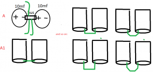
Broadly speaking this would be the better approach.or is it better the other way around?