Proper transformer winding technique?

Hi,
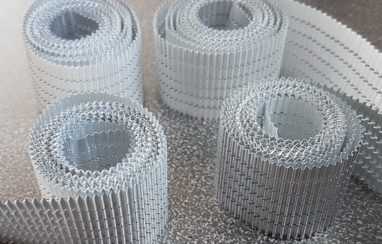
in the past (i.e. in my youth) I've successfully wound dozens of transformers, both power and output transformers, as well as chokes. I did it the, say, German way, using flanged bobbins and serrated insulation foils. Both are (were?) very common here and make winding a relatively easy-peasy job.
Now I've harvested quite a number of power transformers from cheesy transistorized Hammond organs. Unfortunately, most of them feature 115 Vac primary windings, hence aren't much of use for me in their present state. So I'm about to rewind (some of) them. Even more unfortunately they weren't wound on flanged bobbins, just rectangular tubes are there.
That makes me scratching my head now. What precautions do I need to do to prevent the magnet wire from slipping when it comes close to the edges?
Best regards!

Old-fashioned amplifiers with a new twist (1)

Some time ago, Daniel asked me if I could design "discrete chipamps", ie. amplifiers as simple, tolerant and easy as chipamps, but completely discrete in the seventies style, and with additional constraints: single-supply, no LTP, no unusual parts like lat-FETs and transistor count < 9.

Here is the result for the lite version: ~0 to 25W output.

It is the base circuit: the circuit lends itself to various modifications and improvements (will be described later).

attachment.php


It is built to be highly flexible and tolerant: it was initially designed for supply voltages ranging from 3.3V to 24V without any component change, but it can in fact work from less than 3V to more than 30V if the capacitors have a sufficient voltage rating.
All components are non-critical, and it can work with cheap internet parts (my prototype uses some).


The performances are not exceptional, but they are decent enough for such a small circuit, and normally sufficient for most applications.

Since the thermal compensation/quiescent current is always a delicate issue for DIY amps, it uses an automatic class-B bias engine: no adjustment, and only basic thermal coupling is required (this can even be dispensed with completely, more on that later).

The efficiency is also quite good: with a 19V supply, it manages to deliver 18Vpp into a 4Ω load.

The schematic and sim use the D44/D45 OP pair, because it was a preference of Daniel, but in my build I used a BD435 from ST and a BD438 from Philips. Not the best match, but it works with this amp. The VAS is not a BC337, but a CN made S8050.

The simmed THD is 0.04%, against 0.05% in reality.
The power bandwidth exceeds 300kHz.

Here is a pic of the prototype:

attachment.php


And here is the 10kHz, large-signal squarewave response:

attachment.php

Attachments

  • TheOlFashL0.png
    TheOlFashL0.png
    34.3 KB · Views: 4,697
  • OlFashL1.jpg
    OlFashL1.jpg
    449 KB · Views: 3,435
  • OlFashL2.jpg
    OlFashL2.jpg
    283.6 KB · Views: 3,314
  • TheOlFashL.asc
    TheOlFashL.asc
    11.3 KB · Views: 172

Sony HiFi RV22 - STK 403-130 Question

Hi Members

I am new here and I have a few questions regarding the Sony HiFi RV22 - STK 403-130.

I am going to run this Amp separately and I wanted to know about feeding Input voltages, I have attached AMP schematic view.

Numbers Marked Red
1 - What voltage should I input for running 3 number Relay and where from I get that voltage.

2 - How much voltage should I input to mute the sound?


Screenshot 2021-12-04 at 4.41.17 PM.png


Answers will be really appreciated.

FS: Dave Pellegrene custom waveguides with Audax TW025A28

Due to lack of time I'm selling two pieces of these. New, never mounted.

More information:
http://www.multi.fi/~samppo/Audax/waveguide.jpg
https://plus.google.com/photos/101632266659473725850/albums/5934770582575763633?banner=pwa

Original Audax frontplate, screws and shipping carton included.


New price 170 euros/pair (Price 200 euros/pair). I can ship anywhere, ask for shipping costs.

Hypex SMPS400A400 and Bus Pumping

Hi,
I wrote to Hypex to determine the maximum capacitance that can be applied to the output of the Hypex SMPS400A400 power supply to reduce bus pumping. Their response was that :

"It is unsupported to apply extra capacitance on the output of the supply. The surge current could damage the supply."

Has anyone any experience of using reservoir capacitors on their SMPS units - (63volt units) ?
Of course there will be local reservoir capacitance as per the class D amplifier, so the blanket statement that it is not supported seems overly cautious.

Thanks and regards for any feedback on this.

Regards,
Shadders.

Recommend a 30watts to 50watts budget amplifier

Hi,
I need a stereo amp of around 30watts per channel at 8ohms (it could be 50watts also)

I remember more than a decade ago people talked a lot about the T-AMP and some friends recommended it to me.
It was really cheap but performed well.

As a lot of years have passed, probably there's a lot of better choices than the T-Amp nowadays .
I would like to ask you what do you advise as a budget Class-D amp?
Something that I could buy from Ebay ou Aliexpress

I'm not looking for a Kit, I would like to buy an already assembled unit.

Thank you so much

R.I.P Hans-Erik Dyvik Husby (Hank von Hell)

Hans-Erik Dyvik Husby aka Hank von hell sadly passed away 19. November 2021.

Hank was a true multi-artist who has done everything from theatre and opera to hard-rock with great passion and talent.

Outside of Norway he was probably best known for his role in the Norwegian punk-rock band Turbonegro. He was their main vocalist and front figure of the band from 1993 to 2010 and probably played a huge role in their success, both with his powerful voice and great live performances.

Hvil i fred Hank.

ADAU1701 based DSP for sub or 2 way

Happy New Year 🙂

Starting the new year and decade playing a bit with DSP.
Have bought a Sure DSP and programmer board, and gotten familiar with SigmaStudio.

Time to do my own 😉

Would highly appreciate a review for any mistakes or misunderstandings I might have made, by someone much more experienced in ADAU1701 design than myself.

I can make PCB design available if interested ... when I get that far 😉

Design based on ADAU1701 obviously, and NCS2632 to allow for pop free operation.
The output is enabled by a voltage monitor, TCM809TENB713.

I have included 3 general use pots for control, and 3 LEDs for especially peak indicators.

Output 0 and 1 are additionally run through a 10k log pot, for use with e.g. a sub amplifier directly, or my coming party box a la "Soundboks" :djinn:

There is an extension port which is intended to be used for additional or alternative DAC / Codec. I have not included the I2C signals though, which is otherwise the normal for e.g. FreeDSP ... can't really see the use ... but correct me if I'm wrong on this.

/Baldin

Attachments

Two versions of Fane's Full Range Model "Studio 5M" - 100 db and 92,5 db ??

Two versions of Fane's Full Range Model "Studio 5M" - 100 db and 92,5 db ??

Two versions of Fane's Full Range Model "Studio 5M" - 100 db and 92,5 db ??

According the datasheets there are two versions of this midrange model, also suited for full range applications without tweeter:

1) The vintage version, that I know und that I have heard several times (100 db version)
http://www.hifi-studio.de/hifi-klassiker/Fane/Fane_Lautsprecher/Studio-5M.pdf
http://web.me.com/cad/ArenaSounds/Professional_files/Fane_Studio_5M_&_5FR.pdf
Very similar was Monacor's "C5-50M" from Mc Kenzie order code 45.0340 from Monacor's Gerrman catalogue K39.

2) the currently available version "Studio 5M" with only 92,5db sound pressure level but with the same outline (at least according the images by Fane International) go to the new data sheet about
http://www.fane-acoustics.com/downloads/FANE_Studio_5M_Specs.pdf

Perhaps the 92,5 db by the new data sheet is a misprint. Or is it a completly new design with the old model number?

However, the Studio 5MN (neodym magnet version) about
http://www.fane-acoustics.com/downloads/FANE_NEO_Studio_5MN_Specs.pdf
is more close to the old "5M" version than to the new "5M" version.

Who can post exact informations in this case ?
Thank you very much for your efforts.

BTW - I need this informations for replace the transducers in an old near field monitor from d&b, model "E1" - images by post #2 about
http://www.diyaudio.com/forums/full...io-5m-5fr-use-commercial-studio-monitors.html

Most Reliable jFET for Mute Control resp. click-less Switch Function in Pre-Amplifier

A friend of me observe several times unwanted effect on various Linn preamplifiers as follow:

Temporarly or permanently no mute-off after switching (e. g. input select), i. e. no sound.
Reasons therefore were in all cases not the MCU control boards rather one of the associated jFET transistors for shorting the signal pad, which remains in a conductive mode even after the absence of positive voltage at it's GATE pin.
After change by an appropriate replacement this unwanted effect wasn't longer present.
But at whole he observe this issue (defective jFET's) often several times.
Therefore for me rises up the question, what is the actually reason for such faults.
My friend suspects the cause to be that certain type series or batches/charges were deficiencies already in new condition.

Because I have found several defective SOT23 SMD jFETs for mute control in a Linn Exotik preamplifier - go to
https://www.diyaudio.com/forums/analog-line-level/258465-linn-exotik-da-version-lock-2.html
I want to know, which brands and types provide the best reliability for this task.

Thank you very much for an advice.

P.S.: This URL's don't provide the wanted information:
Power-on JFET mute - works perfectly, could parts be reduced?
Muting Circuits For Audio
https://www.diyaudio.com/forums/solid-state/172923-mute-circuit.html
https://www.diyaudio.com/forums/solid-state/194391-transistor-switch-audio-mute.html
https://www.diyaudio.com/forums/digital-source/114664-mute-transitors-veil-sound.html

Siglent SDS1202X-E New to use of equipment.

afternoon all

I have been studying electronics on and off for about a year now and have been repairing old amplifiers with great success, however, as recommended by a few people including mooly, who have really helped me over the last months, its time i started using an oscilloscope as it will help me improve my deeper understanding when testing such items.

The thing is im having a bit of trouble getting started and would really use a bit of help.

I have done all the initial set up with the probes etc, so no issues there.
Its understanding the menus and terminology and what does what.

I would like some help to start with just some basic things i can do.

I have brought a signal generator, (TG 210) but i cant seem to get anything to register on the screen for some reason, so i guess its me and the way i have set it up maybe?
I have followed instructions, but some of the terminology goes over my head

Maybe there is a good online course someone can suggest? that really starts with the basics as i want to understand what i am looking at also when i do actually get to using it properly.

many thanks 🙂

Passive / bass unit / variable cross-over

Hoping for some input on a passive cross-over box design that will allow me to mount various mid-high frequency concepts on top of a wide-range bass unit. This lets me build a variety of smaller experimental units without continually rebuilding the bass unit.

As shown in the overall system design, the proposal would be modify a simple 2nd order High/Low cross-over model with variable length inductor arrays. The amount of inductance on each could be changed together using something like a "KCT 2 Pole 6 Position Dual Decks" rotary switch ($8).

In X-Sim it can be shown that choosing a 20uF capacitor on each side, varying inductance from 1mH to 10mH changes the cross-over frequency from 300hz to 1.1khz.

10 mH - 300 hz
7.5 mH - 400 hz
5 mH - 500 hz
3 mH - 600 hz
2 mH - 850 hz
1 mH - 1.1 khz

An optimal solution would be 6 separate cross-overs, each with their own capacitance value. Help me understand why that's worth the effort?

This design could be built using 2 x 20uF capacitors, 3 x 1mH, 1 x 2 mH, and 2 x 2.5mH inductors, wired in series to the next inductor and the switch, on each side (8 passives) along with whatever BSC filter you need on the front-end.

Looking for critical feedback and improvement ideas. Thanks in advance!

Attachments

Blue Hawaii amp problem

Hello,
I have a problem with my Blue Hawaii amp.

I just moved from Canada to France and when reconnecting my BH amp, only the left light gets on, the right one stays off and there is no sound.

The amp was built to be plugged on a 230v power source which is the French standard.

I tried to contact Headamp and Justin (phone and e-mail) with no chance so far.

Can someone help me identifying what could be the issue and if I can solve it by myself? It would be helpful if I could know if it is coming from the amp or the pre-amp.
Thanks in advance for your advises!

My kindest regards
Eric

Testing for SuperReg-2020

:cop: This thread is split from:
Super Regulator

____________________________________________________________________________

My read for the ad825 ds is 76dB for Av(ol), for +/-15 rails. Were you using the part 5v data?

If the reg Z(ol) is 1 ohm, the closed loop Z(o) will be around 150uohms (1/6500). This seems to be about what a good current day SR can do. Why do I say that? I just recently measured Z(o) to be roughly that, but limited by the noise of the test setup, as working with a dynamic load of 100mA. More on this shortly.

It is worthy of note that a SR running with a dh44 pass device may need some additional loading to get the open loop Z down. I am running my preamp at more than 100mA total (each rail) for that reason (even though the active stages are lower drain).

All that being said, I am one observer that feels the regulator Z is a very important spec.

Walt Jung

I am uploading my preview document for a tester useful towards exercising SR circuits. It offers useful info on cap ESR and regulator Zout, using the AD825 in a SR2020 circuit.

It will also be available from my website via this link.

Walt Jung

Attachments

Measuring host bases equalizer distortion

Wondering if anyone has an idea how to some sort of generation, through the EQ, (APO/Peace) and back in to measure the distortion.
I thought one could generate a tone through the EQ to a file, then read the file into RightMark or something.

I don't need much eq. I wonder which is cleaner, host based or something like the Schiit tank based little 6 band box.

Online shop for ribbons

So I have been doing this for a while now and I thought that I might just as
well set up shop. In doing so I figured I should ask potential customers before
hand what I should keep "on the shelf". So if you have nothing better to do, I
would appreciate specs for what you might order in the future.

There are a few examples at the store already, some might be around and
some might be replaced. There is always a possibility to order "custom ribbons"
but if it's on "on the shelf" it will ship the next day from order.
Custom orders will usually ship within a week or two.

Best regards: Bengt Dahlberg
DahlbergAudioDesign

26%2C5mm_mc-1620724002030.jpg

PassLabs X600

Tomorrow I will haul (yes haul because they are a backbreaking 132 lbs per channel) a pair of PL X600's, the first incarnation from 2000 or so.

I have e few questions regarding these amps.
After reading the Owners Manual (very witty and with loads of technical information like the Aleph series OM's) I do not understand that the XA-160 and X600 both consume 600 Watts, have the same hardware, get evenly hot but the XA160 can produce 160 Watts RMS of Class A power and the X600 "only" 40 Watts. So same temperature, same hardware, same AC current-draw but different biasconfiguration. Is the increased railvoltage to get 600 Watts out of this amp at 8 Ohms responsible solely for the diminished Class A portion?
Just curious because I know that meter won't move that much in real circumstances with 80 Watts Class A peak power.

Can I perform updates myself, like installing a new frontendboard and then calibrating the amp again?

Apart from the filtercaps, which are probably more than 20 years old, is there any part I should replace asap you know of? Or (a) part(s) that would the raise level of performance sounds wise relatively much?

After a lot of Threshold gear, this is my first Passlab so I'm a bit new in this field. I know PassLab evolves to .8 status nowadays but I can't afford these (yet) and I have powerhungry and non efficient Infinity's so I need a potent set of amplifiers.

Are these amps stable in 4 and 2 Ohms?

Thanks in advance.

CT Sounds 7k

CT Sounds 7000.1

Working on a pair of these with the same problem; 1/2 blown PS, but the audio sides seem to be OK. Seems one of the amps will actually still power and play, but part of the PS smokes and obvious visible damage.

I have a chance to fine-tune the supplies in these if there are any slight circuit modifications to help with reliability. I had done something similar to a Lanzar 6k which was choking below 12.2vDC supply voltage - made that one run reliably down to about 9V by changing out the gate resistors to a lower value.

This amp is already running lower gate resistors then the Lanzar, and this amp has twice the PS driver transistors.

-PS Fets are IRFP1405 which there are 24 total in each amp - I have a sleeve now on order to replace.
-Drivers were KTC2814/KTA1715 and mostly blown, which I plan on replacing with MJE182G/172G. Amp has 8 driver transistors
-470ohm resistors before the above drivers connecting back with 200 and 400 ohm resistors to the PS driver board.
-PS Gate resistors are 22 ohms. Many are out of spec and so I'll be replacing all of them
-3.3k pulldown resistors

With no PS fets, this setup gives a perfectly clean square drive from 8v to 16v supply

Anything here need any tweaking by chance?

Horning Alkibiades - Fullrange with very high frequency Tweeter ? - Crossover Network

I am looking for test reports, technical details and the schematic of the Horning Hybrid System model "Alkibiades" (Horning's first loudspeaker model - so I think).

Who can upload this?

The only test report, that I know, was in German's magazine "IMAGE HIFI" issue 3/1995 - for a cover picture of those magazine go to ebay auction
Image HiFi 3 Denon PRA POA DCD-S10 Conrad-Johnson PV10A | eBay

some URLs:
Lowther. - Page 3 - The Art of Sound Forum
Alkibiades Loudspeakers Loudspeaker Manufacturer & Wholesale Supplier From Denmark - Horning Hybrid Systems
Audio Asylum Thread Printer

There are no details on the web arround this loudspeaker.
Thank you very much for your informations.

Attachments

  • Horning Alkibiades.jpg
    Horning Alkibiades.jpg
    138.3 KB · Views: 959

  • Locked
How to attach images to your posts in XF

How to attach images and files to a post is a question that repeatedly crops up. Hopefully as this quick tutorial will show the process is quick and easy.

Go to the following options depending on what you want to do.

Option 1. To insert a single image or a group of images.

Option 2. To insert an image from a web page.

Option 3. To add non standard files. These would be ones having file extensions not natively handled by the forum.

We would also ask that wherever possible you make full use of the forums imaging handling and storage facilities rather than just linking to a set of images held on a 3rd party hosting site. The reason is that these 3rd party images usually don't last for long as the poster either deletes them at some future time or the account holding them falls into disuse. We want your work to be here forever. XF (XenForo) the platform that we are now using has far better image handling than the old site.

Option 1: Attaching an image or a file stored locally on your PC.

To do this simply click the 'Attach Files' button at the bottom of the message reply box. This will open a Window that will allow you to browse your PC for the images or files you want to add.

Note. XF allows for multiple image uploads. Simply select all the images needed and click on 'Open' when you have have them all.

Image 1.jpg


Or you can click the Image button here.

Image 1B.jpg


Image 2.jpg


For example five images have been selected here. Having selected the image or images or file select Open. All the images selected will now load to the site.

Image 3.jpg


Image 4.jpg


Having now got the images uploaded to the site they now have to be added to your post. If you click 'Insert Multiple' then a new set of options will appear and which are fairly self explanatory.

Image 5.jpg


Each image has a 'tick box' in its top left corner. The options on the toolbar below the images allows you to select them all as a group or individually and also gives the option of how you want them to appear, either as thumbnails or a full image in the body of the post.

If you have uploaded just a single image then these options appear in the uploaded preview image.

An inline image is inserted at whatever point you have the cursor.

Note. Once an image is selected you also have the option to delete that image off the system which is useful if you uploaded something in error. The 'Bin' icon on the tool bar is active once you select at least one image.

Image 6.jpg


You can also individually decide for each image by clicking the 'Insert Image' text on the preview images. This will then open to give you a choice.

Image 7.jpg


-----------------------------------------------------------

Option 2: Adding an image direct from a Web page.

Providing the image is within the forums max size limitations and is of a file extension allowable then you can simply copy and paste that image into a post. The insertion point will be wherever your cursor is in you post.

You can also Drag and Drop images into a post from different sources. For example a second open browser window or your PC itself.

The same also applies to images on your PC. You can also just copy and paste these into a post.

------------------------------------------------------------

Option 3: To add non standard files. Use this option when the file/s you wish to upload have file extensions not recognised by the forum.

Placing any such files into a Zipped Folder and uploading the whole folder will allow you to add non standard files to your posts.

Ceramic PCB one-stop manufacturing (achieve 3D design)

News:

Are you looking for a one-stop ceramic manufacturer for your project of power-supply modules, car-class IGBT modules, solar battery modules...?

PCBONLINE is a competent partner for ceramic PCB projects for these advantages:

  • PCBONLINE adopts DPC technology that can achieve 3D design;
  • High-density capability - 20μm minimum line space;
  • A better welding performance and high-temperature resistance;
  • No oxide layer on the circuit layer and longer shelf-life;
  • Free one-on-one engineering support (DFX);
  • Online register, instant quote, and $100 coupons for online purchases.

Email: info@pcbonline.com
Visit our website:PCBONLINE Official: Middle and High-end PCB Manufacturing and Assembly

High Frequency PCB Manufacturing | Professional Solution Experts | DFX

Hi, here is PCBONLINE, a high-frequency PCB manufacturer. Finding a reliable manufacturer is the key step to making sure no issues in high-frequency PCB.

PCBONLINE will:

Help you solve any issues in your PCBs and provide one-on-one engineering support;
Help you choose appropriate base materials of stable and low DK/Df with the highest cost-effectiveness;
Manufacture high-speed/high-frequency PCBs of 4 to 8 layers;
Achieve RF interface and signal interface on the same high-frequency circuit board;
Provide free design for excellence for your projects and make sure to yield successful results.

Visit PCBONLINE' high-frequency webpage: High-Frequency PCB Manufacturing 100% Successful - From Materials to Assembly
Contact us by email: info@pcbonline.com.

Or feel no worry to contact us online!
rf-pcb.png

SP3T Switch?

Hi, all,

I've just built a set of Troel's Gravesen's Illuminator Monitors, and they are amazing! Just for the sake of it, and to experiment more easily, I'm thinking of adding a switch that will allow for various levels of tweeter attenuation. Does anyone know of a single-pole three-way switch that would be suitable? I'm guessing that the Goldpoint switches, being made for line level, probably are not suitable. I can't find anything on Mouser.

Riki

Attachments

  • 20211209_193253.jpg
    20211209_193253.jpg
    295.2 KB · Views: 131
  • 20211209_193306.jpg
    20211209_193306.jpg
    259.2 KB · Views: 121
  • 20211209_193324.jpg
    20211209_193324.jpg
    253.7 KB · Views: 108

Bruno strikes again

And yet again Bruno strikes, with yet another D module, this time it almost doubles down to 2ohms!!!!!!!!
Seems in this one he gets grunt (almost doubling) right down to 2ohms, not just shelving off at 4ohm and running out of steam any lower.
VTV are going to use them, this looks a bit messy though, maybe a prototype VTV Purifi High Power Module | VTV Amplifier

Bruno strikes again. Purifi 1ET7040SA VTV Amplifier. Sinad 109. 950 watts. - YouTube

Cheers George

Heathkit IG-5218 Sine/Square generator give away ..

Hi all,

I have a Heathkit IG5218 that has been modified according to the former diyaudio member richiem's (Dick Moore's) suggestions (also for battery operation). Webpages here (half way down):

Home -- article index

Last time I used it it worked (battery switch-on may be teasing), however, not fully to the specs that Dick Moore achieved (to my memory 2H is about 100 dBs down). So I reckon there is an error somewhere but since I will be moving shortly it is time to part with it.

It does contain some likely interesting parts like LT1468, film capacitors, RN60/55s, and possibly more - and also the switches for making such an oscillator (according to richiem's suggetions) should someone be interested in doing so (FYI I cannot offer to provide any support in working with it).

No cost other than shipping (located in Denmark) - and time limited until 24. September (2021).

Cheers,

Jesper

Attachments

  • IMG_20210920_085802.jpg
    IMG_20210920_085802.jpg
    189 KB · Views: 229
  • IMG_20210920_085750.jpg
    IMG_20210920_085750.jpg
    399.9 KB · Views: 218

Calculating Power Handling by Frequency

Is there a formula (however imprecise) of calculating a driver's power handling according to frequency range?

In a traditional 2-way system you can use ROT of an 80/20 split, 65/25/10 for a 3-way.

But in modern systems I can find no guidelines. e.g. Let's take a pair of 2-way 100w full-range speakers being used in an AV system. Add a sub, and crossover at 100hz. (Ignore the tweeter) What is the new power handling of the full range cabinets?

I'm interested in this because I've dismantled several commercial units. It explains why a Yamaha YST-SW60 sub has a driver stamped 25 watts.

Soundstream Rubicon 1002

Have A question. I have NOS of these A1304/C3296. The C3296-y have a hfe of 216, (all 15 of them). The A1304, they are green with a "T", they have an hfe of 160, six of them, and the rest have lower numbers. Using these in the Rubicon 1002, I was wondering if they will upset the bias as they are not equal?
I can get KSA940/KSC2073 from mouser which have the same specs.

Reason...Its been a few years (10+) and decided to get two of these going. The power supplies are good and I have NOS 2sa1302/c3281 that I'm going to install. The best matched sets. Front end boards are new from Lance, (X-Soundstream employer) so those are good.

When I set and measure bias, (1.5mV across the emitters of one pair a1302 and c3281), The other pairs measure lower and there is a difference between the pairs. One emitter resistor has 1mV and the other has 0.5mV across them.

Only thing I can think of is the hfe difference between a1304 and c3296.

Am I correct?
Scott

Attachments

  • Bias.jpg
    Bias.jpg
    86.5 KB · Views: 117

Replacement Peavey CS-800 Power Transistors?

This unit has -81 0 81 VDC rails and NPN only TO-3 transistors.

The factory transistors are SJ6343B by Motorola on one channel (this channel has likely been replaced with a newer factory board at some point) and RCA 68271.

I'm guessing these are proprietary Peavey transistors that are similar to something existing. Is there a suggestion that would work for this old amp? I have two shorted transistors on one of the channels.

Dayton B652 Air Outdated BSC crossover mod

I was recently gifted with a pair of the Dayton B652 Air bookshelf speakers.

They sounded like they have potential, but the treble is at dentistry levels of brightness. Plus cone breakup, etc etc...


So I looked for various crossover mods. This is the one I thought was the smartest way to go:

Fun with the Dayton B652-AIR -

Techtalk Speaker Building, Audio, Video Discussion Forum


So I ordered the parts.

I figured it should still work since the B652s still come with the same crossover components as the modder reported.

However it seems this mod is out of date, as well as the data from the Noaudiophile review. When I measured the speakers with and without the tweeter reversed, the result was almost identical (although the Noaudiophile DSP correction file has the cone mode filter in the right place).

The B652s have been revised in the past, IIRC the woofer cone depth was changed and the crossover was also changed.


In any case, the mod seems to be a reasonable starting point. The first thing I had to do was add a 2.2uF capacitor in parallel with the 4.7uF in order to shift the resonance filter to the new cone mode frequency.

However I'm left with a notch at the crossover frequency. I figured I would post this before finishing in case someone has already got this sorted out or takes one look and knows what to do.

Here is the original BSC mod:

attachment.php


First line is stock B652 with the BSC mod.
Second line is with tweeter reversed.
3rd line is with 2.2uF added in parallel with the 4.7uF cap to get the correct resonance frequency.

So, any thoughts on the best way to fix the notch? It seems changing the 2.2uF cap is the first thing to try...

Attachments

  • 1-BSC_2-BSCreversedtweeter_3-plus2.2uF.png
    1-BSC_2-BSCreversedtweeter_3-plus2.2uF.png
    42.9 KB · Views: 622
  • crossover.png
    crossover.png
    4 KB · Views: 2,280

Radio station comes through phono stage, only fixed when I grab the wires??

When my phono stage is running at high-gain (59dB), I pick up a nearby radio station through it. I've tried all sorts of things with cables and positioning. I realized that if I lean my arm on the cables, or grab them, or even just hold a lead clipped to the body of one of the connectors, it completely attenuates the radio signal. I haven't been able to replicate this with any other technique.

What's happening? What is my body doing that connection to ground isn't? I should note that my phono stage uses a wall-wart AC transformer and is not grounded, although it does provide a ground lug.

UPDATE: Clipping a 3' test lead to the ground lug on my phono stage and simply draping it under the shelf my equipment is on eliminates 90% of the interference. It's not connected to anything. In fact, connecting it to anything, including another lead, brings the interference back. I'm so confused...

  • Locked
The migration is happening today at 11AM UTC

The migration to our new platform will be happening today at 11AM GMT/UTC, Wednesday 8th December 2021.

You can check the time in your city here:

The diyAudio migration time in your timezone and cities around the world

The site will be down for 24-48 hours while we perform the migration.

I look forward to seeing you on the other side, and to having a fresh new starting point from which the community can grow in the years ahead.

If you would like to discuss the migration, please do so here:

We will be updating our software platform mid-December

What BJT drivers still avail?

looking to procure some drivers for a power amp output stage. I see a lot of the classics are no longer made. Looking for a driver:

Vce = 200-250v
hfe = 100-300 @500ma
Pd = 25w-150w
cob = prefer lower values ....

Looking at the 2sa1668, its gain compared tp the njw0302 is similar .... wondering if I should just use njw0302 as drivers since I have many of them

Wondom JAB5

Hello All,

After watching quite a few youtube videos about the Wondom JAB5, I became interested in a particular pair (in some videos) and sometime two pairs (in other videos) of Pioneer Speakers. I contacted Wondom (Lillian in Customer Service or Customer Relations- Pre-Sales) to ask about these Speakers. She didn't give me any info so I asked where I could buy them and she stated that Wondom would sell them to me. Has anyone seen these speakers? Are they anything special. I can't find them for sale anywhere. Any input would be appreciated. Thank you.

Signal direction of RCA from AQ are wrong or I'm wrong

Hi there

I bought 1set(R,L) of 2meter RCA cable. I want to split them to 2 sets (1meter each) so I cut them in half and to expect to see 2 wires and a shield. Instead I found 3 wires and a shield. That would be no problem to reconnect to new RCA jack just to use multi-meter to test how they are wired for each. But what I found is strange, each cable (R and L) are difference wired.

In the photo there are yellow, white, blue and shield. Same direction arrows but the White arrow jack: all white, blue wire and shield are connected to jack ground.

While the Black arrow jack: only white wire is connected to jack ground. 😕

view

view


For this side of arrow, both cable had same wired: white and blue are connected to jacks ground (no shield connect)

view


Is this factory or something?😕

If mistake by factory, any one know how to correct them or how to connect for each direction? For 3 wires and a shield?

(For 2 wires and a shield: one wire should combine to shield at one end and separate at the other end. )

What could be done with Fisher STV-880s?

My elderly father-in-law is quite the music buff, and uses ancient Fisher STV-880 3-way speakers (15" bass driver) with Fisher separates. They sound terrible, but still work.

He's got a fair amount of basic woodworking gear, so I'm wondering, what might be done (economically) to improve these speakers, e.g. keep the cabs but make a new baffle with new drivers + crossover?

They sit right up against the wall which is the only position they can be placed in this room.

Pic - basic chipboard cab with dual front ports, 36" (h) x 18" (w) x 13" (d) so maximally 138 liter volume.

Attachments

  • 1.jpg
    1.jpg
    233.6 KB · Views: 593

old school type woofers that require a monkey coffin

Are there any sources of high quality (new, not used or NOS) drivers that have the sort of TS parameters of the 1970s and 1980s, when loudspeakers used very large boxes? These would be very high compliance (high Vas) high efficiency drivers with low Xmax. I am especially interested in 10" and 12" woofers. These are nothing like today's "subwoofer" drivers but could play low if a very large box was used. They might have more in common with some pro-audio drivers that can be found today.

Where can I find this kind of driver? Any particular models I might look at?

Interesting GM70 scheme... Some questions on the PSU, who helps me please?

Hi,
i was looking for a good GM70 SE project, and stumbled upon this blog:

GM-70 SE amplifier | Firebottles!

All the credits go to the Blog owner, named Vincet Duparc (still wonder whether he's on the forum?).
I tried to comment on his blog, but no answer came, perhaps these pages are no more curated.

Well, the PSU seems very well designed, regulated but no stabilized, but there are some components that are quite uncanny to me (what they are, how are they controlled.).

In the second attached schematic, the PSU, I circled in red my doubts:
i) I see two relays on the HT primary, one "tempo" shoud be a time delay one, that will be shorting out R27; same should apply to the inrush current limiter that shorts out the thermistor NTC2. Am I right? I think they should be 250VAC/3A, right?

ii) what are these F7/F8/F9 points before each mosfet ?

iii) in the second attached picture, there is another inrush relay that will short out NTC1, and ok, same as before.

In his blog pages, third schematic, there's an arduino controller for temperature and gm70 bias current (third attached picture). This drives a cascaded darlington ULN2003, that controls three relays, one for power, two for inrush limiting.

iv) are these three relays the same in the PSU schematic? I wonder why, if the controller switches them open, there still will be thermistors through which current flows... What am I missing?
If this is not the case (these 3 relays are not the ones in the PSU), where are these relays attached to?
I mean, the arduino schematic rationale seems to me as being 10V in, inputs from thermo sensors, inputs from bias current, and output what?

I really hope you can help me open my eyes, safety is always not enough with handling 1,1kV....

a big thank you!
Mike.


On the Distortion of Ribbon Speakers

I searched the web for information on the mechanisms of distortion in ribbon speakers, but I found only hypotheses, reasoned and even shareable suppositions, but no ad hoc measures. Maybe those who make these speakers know all about the subject, but if so, they keep it to themselves. So being a DIY enthusiast of ribbons, I decided to do some research, within the limits of my cognitive and economic possibilities.
One of the assumptions that everyone (myself included) has made is that a primary mechanism of distortion arises from the non-uniformity of the magnetic field
The distance between the pole pieces, having to contain the width of the strip, is always relatively large with respect to the height of the expansions themselves, therefore it is normal for the ribbon, during large movements, to operate within very different magnetic flows.
So as a first step I wanted to verify and possibly quantify this hypothesis.

As a first approach to see how much magnetic field uniformity affects THD I used the ribbons in closed box which I have already extensively described in another thread, my ribbons full range in CB - diyAu...ngine Long_base_field Long_base_0 Long_base_8

Attachments

  • rib 46 real1.jpg
    rib 46 real1.jpg
    359.4 KB · Views: 597
  • Bx30mm-8mm.jpg
    Bx30mm-8mm.jpg
    59.4 KB · Views: 617
  • Bx30mm_centro.jpg
    Bx30mm_centro.jpg
    53.3 KB · Views: 583
  • Bx30mm+8mm.jpg
    Bx30mm+8mm.jpg
    57.5 KB · Views: 587
  • long_base_field.JPG
    long_base_field.JPG
    131.8 KB · Views: 594
  • long_base_0.jpg
    long_base_0.jpg
    130.7 KB · Views: 179
  • long_base_8.jpg
    long_base_8.jpg
    130.8 KB · Views: 147

Question re: Williamson amplifier and stability

I've been told many times and have read many places that the Williamson push-pull amplifier topology is inherently unstable. But... I'm not sure if that's a valid blanket statement.

1. Of course it's true that the Williamson design has a lot of RC-coupled stages, with multiple poles. Also, the OPT adds another pole. If two poles are close in frequency but out of phase, and the usual 20dB of global negative feedback is applied, oscillation will surely result. But...

- What if the poles are staggered so that no two poles are too close to each other in frequency?

- What if MOSFET source followers are added after the differential driver stage, so that the F3 of the RC network between the diff driver and output stage can be chosen so as to be far away from other F3 points in the circuit?

- What if there is much less NFB wrapped around the circuit? Let's say only 6dB of global NFB applied?

- What if *local* NFB is employed between the output stage and differential driver? Perhaps from the plates of the output tubes to the cathodes of the diff driver tubes? The F3 of the RC network in the feedback loop could be chosen so as to be far enough away from other poles, or low enough to be out of the way of the OPT LF pole.


2. It's also true that the original Williamson had not-so-well filtered power supply decoupling, so low frequency stability (motorboating) was often a problem.

- What if stiffer, higher capacitance decoupling networks are employed, or capacitance multipliers, or even voltage regulation on the driver stages? With the decoupling going down well below 1Hz, wouldn't that keep the motorboating tendencies at bay?


Thoughts?

--

Replacing choke frame

Hi there.
I bought a pair of Hammond 194E chokes to replace a pair of 175G (of lower rating) that I have on my home made amp. Both models are open frame types.

The new chokes are larger (EI-76 lamination) and wouldn't fit comfortably in my chassis, so I decided to remove the frame and replace it with end bells that I found on eBay so I can mount the components vertically.

While removing the frames, some of the varnish came off the core. The tool I used scratched off some of the gray paint on the core too. I also noticed that the top part of the lamination is detached from the "E" frame by means of a plastic layer on each side.

A couple of questions:

Is there any particular varnish that you suggest using to seal the chokes? I was thinking about plain clear spray paint.

Is it OK for the two parts to be just kept together by the end bells, or are any possible gaps an issue? (I imagine that if the end bells fit exactly there shouldn't be any gap except for the plastic separators that were in place already, but I haven't received them yet and cannot tell).

Any other advice on this?

Thanks.

High-quality portable system: where to start?

Hello there,
I am entirely new to chip amps but have done some PCB and P2P assembly on tube amps before.

I want to build a high quality, battery powered amp + speaker that I can take around and sounds better than my run-of-the-mill Cambridge Audio USB speaker, but need not compete with my 300B SET.

My parameters:

- Battery powered. Ideally I would like to use my DeWalt power tool batteries. I have a few 20V, 1.5Ah Li-Ion batteries and charger, and probably could buy a higher-capacity model if needed. I could scrape a broken tool "for parts" to get the battery shoe and attach it to the sound system.

- Mono. Rather than cramming 2 channels in a small box, if I wanted a true stereo image I'd rather build 2 of these. But that is not a concern at the moment.

- Loud enough. The reason I'm starting this project is that my USB loudspeaker proved absolutely inadequate for an open-air dance session that I recently set up.

- Compact. Ideally a 8"-10" cube.

- Good sounding but not necessarily "audiophile" grade. I have my Hi-Fi set up in a quiet room for that.

- Decent life: at least 1 hour operation at high volume per battery (30Wh).

- Reasonably priced: if possible, under $150 with loudspeakers (hoping to save on batteries by using my DeWalt ones).

Where shall I start? I read some threads about Gainclone which seems to be a good candidate, and even saw some kits with and without IC on eBay at affordable prices (even for eBay). But the options and variations seem overwhelming to me. Which chip shall I use? How do I pair chip, battery voltage, and loudspeaker(s)? Any good tutorials to read for understanding the basic parameters?

Thanks a lot for the advice.
gm

EV PSX 2000 stuck in protect

Thought I should share this tip: The schematic for this unit is available but barely legible for finer detail. After a bit of a struggle :/ :/ If you have one of these that looks like should be OK, but won't come out of protect: Change C824 (10uf/50v). This cap was leaking electrolyte but not visibly. As soon as I heated the leads to remove the cap - obvious electrolyte smell. The protect circuit is driven off the -Vss rail and involves an array of transistors (Q809 thru Q816) and looks like C824 provides a time out to ramp up a -24v feed for relays, muting circuitry and the protect LED. C824 is located near the edge of the power amp board.

LM1875 Stereo Amplifier with integrated PSU

Hi all,
I always wanted to create something for a beginner which is simple to build and very convenient and yet cheap.
what better chip than LM1875, 'the beginner's Hi-Fi' or ' beginners gainclone'.

Criteria was just a single cheap Chinese boardhouse pcb, left and right channels on the same pcb + PSU + all though hole components.

so just pcb + heatsink +center tapped transformer + some hardware and a cheap case is all that would be necessary to build your own 'my first hi-fi amplifier'

or it can also be a learning exercise for young ones who are interested.

One thing to note here , THT + all in one (stereo +PSU) PLUS small PCB dont go hand in hand. so one cant expect loads and loads of capacitance in power supply section.

I havent tested it, but layout follows the schematic perfectly. comments welcome.

Cheers to the spirit of DIY.🙂

regards
Prasi

Attachments

  • lm1875stereo-sch-R3.png
    lm1875stereo-sch-R3.png
    12.9 KB · Views: 849
  • lm1875stereo-R3.png
    lm1875stereo-R3.png
    77.4 KB · Views: 891

Altec 1570B mods

I have a pair of these and need directions to bypass/eliminate the 70hz filter on the 12ax7 front end input. From what I've gathered, extensive mods are not needed in order to render these amps hifi. I have basic skills and have done good work with good direction. If there's someone here familiar with this amp it would be greatly appreciated. 🙂 They are in great shape to begin with.

Questions ideas regarding waveguids // port design t-line

Hello there,

I´m back with a few general Questions considering T-Line design and some other stuff as well.
I play around with Hornresp, and came up with to designs I wanted to try.
I build tow Test speakers, and experimented with different cross sections and “Tapers”.


One Speaker is tuned to 95Hz

20211126_204506.jpg

: it is the winner in a direct sound comparison between those tow, got better dynamic range and the sound apers to be more open, all thou a tiny bit more “blurry” but all the details are there. The other one has a less dynamic and the sound is more concentrated in a small spot, but the detail´s seem to be more pronounced this one is tuned to 109Hz

20211126_204511.jpg.

A Few things must be said first:
-the sound only was quantifyed by hearing
-the speakers do have different tuning and maze-layouts
-the enclosures where designed to be operated with filling, but I didden´t do that... big dump

These tow speakers led to a few Question and ideas which I hope to be somewhat constructive.

First of all doas the maze layout affect the sound, sure it doas:
But could it be in some way desirable to have a symmetrical-ich layout of the maze next to the speaker. (since the better sounding one of my speakers cinda is symmetrical while the other is not, could this be one of the )many( reasons). This assumption seems intuitif right but is it thou?
=>Should I design my next test subject in a symmetrical way or is that irrelevant?

How doas sound travel through corners: (illustrated with drawing for better understanding)

20211126_204223.jpg

a: doas it travel the way with half the radii?
b: doas it teak the way with the radii where both left and right volumes are the same?
c: neither of those
What effective distance sound travels in “corners” and how is it calculated?
(The final speaker´s are required to be very space effective. Having the sound travel a grater distance in “corners” than I´v assumed would play in my favoured)
i`ve been going with a: but now b: sound´s moor plausible to me


Tapering the Port: (sketch fore better understanding)
making “corners” tapered is quit hard to accomplish but having a linear taper along the way is also difficult fore me to accomplish. So here I wanted to check if the way I plan to integrate tapers in my design is applicable.

20211126_204231.jpg

a: ideal Taper
b: this is how I tested Tapers in my speakers
c: this is how i´m going to design the tapers into the speakers
My design:
-As mentioned no “corners” are tapered (blue in sketch)
-I divide the port in 6 sections where each section is a different length
-The volume each taper teaks away from the maze is identical
i`m going with it any way except it is a super bad thing to do, but I imagen this being good enough.

How about putting waves into the waveguides edges: (with sketch)

20211126_204353.jpg

This approach is normally used to lover the pressure level´s of a port do to the increased surface area. I´m wondering if such design could help reduce resonance or benefit sound in any other way. I could Imagen that such a waveguide design increases the bandwidth the port covers do to the on some parts increased/lovered distance the sound has to travel?
Or dosen´t it affect sound at all?
Would be nice if you could share your thoughts or experience on this.
If anything is known abut the effects of such waveguide edges is known pleas let me kno.

Thanks for making it this fare, You are encouraged to share your thoughts on every thing I mentioned above.

Thanks fore reading, have an awesome day.

Klipsch Belle crossover type AA cap replacement

I've been looking for a set of La Scallas or Belles for years and always seemed to be too late, poor condition or overpriced. Was about to pull the trigger on a new pair of Forte when last week I drove 600 miles round trip for beautiful pair of 78' Belles. I would like to get some opinions on replacing the 13uf 200v and 2uf 200v metal caps with Gen 1 Sonicaps. These are sold from Crites in kit form for $215 and Sonic Craft individually for $188. Will this make a big difference? Also thinking about gutting the cans and retrofitting the new caps inside to keep the authentic look but not sure if it's worth the mess of cutting open, cleaning out, fitting and resealing just for looks when no one but me will ever see it. I am astounded with the efficiency of these. I never believed the specs when I have read about them. All true. They sound beautiful through an R-8 but have some weaknesses that tell me the caps are past there prime. Any advice of experiences with these would be appreciated. thanks

PHL Audio's new 5" transducers (900 series) who have heard this new devices?

By chance I discover this new PHL loudspeaker driver series:
PHL Audio: Products ?*5 inch in
Boutique haut parleurs et audio DIY
Who have heard one of them and which commercial available loudspeaker products are equipped with this drivers?
Most of interest are the follow:
900, 973 (both low-mid) so as 930, 982 and 983.
Thank you for advices.

Replacement/Repair of LF-5 with TPX Cone from HARBETH ACOUSTICS (Swisstone, Harwood)

A diy monitor box from a friend with Scan-Speak dome tweeter D2905 without ferrofluid and the above mentioned Bass midrange driver need service.
The LF-5 is faulty on both channels - both overloaded voice coil and and adhesive connection between rubber surround (suspension) and TPX cone/diaphragm damaged.

Which replacement comes closest to this chassis regarding sonic character (which was excellent in genuine resp. working condition) ?
Maybe the PHL 900? - go to post # 28 under
Error 404 - Page Missing
or KEF B110 SP1003
KEF B110 REPLACEMENT SP1003. FALCON B110 8 ohm. MATCHED PAIR. MADE IN UK.

A second question: Which company has specialized in the repair of these chassis with TPX membrane (also the LF-8)?
Thank you for your advices.

Some URLs:
Vintage Speaker drivers
Hifisound Der Spezialist fur Lautsprecherchassis
hifisound - Katalog 97/98
http://www.hifi-forum.de/viewthread-104-21059.html
https://www.analog-forum.de/wbboard/index.php?thread/43337-harbeth-spendor-co-thread/&pageNo=22

https://www.hifisound.de/de/Historie/
https://store.acousticsounds.com/PDF/Harbeth-Feature-Article.pdf
https://harbeth.co.uk/harbeths-history-in-speaker-cone-research/
https://www.inputaudio.de/wp-content/uploads/2015/06/Hifi_Ch.HL5__4_stars.pdf
http://audioconnection.se/res/HarbethAudiobrochure/harbethflyer.pdf

P.S.: this thread don't provide the wanted information:
https://www.diyaudio.com/forums/multi-way/229388-harbeth-hl-mk2-replacement-drivers-re-cone.html

Attachments

  • Harbeth-ML-BBC-Monitor-12.jpg
    Harbeth-ML-BBC-Monitor-12.jpg
    49.1 KB · Views: 263
  • Harbeth LF-5-VIII.jpg
    Harbeth LF-5-VIII.jpg
    25.9 KB · Views: 188
  • LF-5.jpg
    LF-5.jpg
    22.9 KB · Views: 175
  • Harbeth LF-5-V.jpg
    Harbeth LF-5-V.jpg
    231.8 KB · Views: 169
  • Harbeth LF-5-VI.jpg
    Harbeth LF-5-VI.jpg
    249.1 KB · Views: 174
  • Harbeth LF-5-VII.jpg
    Harbeth LF-5-VII.jpg
    242.1 KB · Views: 163
  • Harbeth LF-5-III.jpg
    Harbeth LF-5-III.jpg
    293.8 KB · Views: 206
  • Harbeth LF-5-II.jpg
    Harbeth LF-5-II.jpg
    274.5 KB · Views: 175
  • l_harbeth-lf5-mkiiic_1.jpg
    l_harbeth-lf5-mkiiic_1.jpg
    23 KB · Views: 191
  • dsc00021_19169.jpg
    dsc00021_19169.jpg
    39.3 KB · Views: 184

Sonus Faber Extrema clone

I know this has been on here before but I am at a point that I need some help.
I have drawn the SF Extremas in AutoCAD using photos I scaled from known dimensions to get the general shape as close to the original as possible. I have sourced a set of KEF B139 for the passive radiators and a set of Chinese cloned Dynaudio tweeters.
The cabinet will be a laminate of 3/4" MDF with hardwood sides. I have had the templates cut from 5/16" aluminum plate which will allow me to cut the general shape of each laminate piece and then use a flush bit on my router to get them to the exact shape. Each template has 1/4" locating holes to be drilled and fitted with 1" dowels. The front plate that will eventually be wrapped in leather gives me the freedom to try different drivers. The calculated internal volume is 20 liters, just like the original.

Where I need help is the woofer selection. There are so many to choose from it is a bit overwhelming.
Thank you in advance
Dean

Is This XE350 (XE350C) PCB Worth Building? (Class AB or A Based On Accuphase???)

Does anyone have experience with (or opinion regarding) the attached (PCB and schematic) for the "XE350" (XE350C) supposedly based upon Accuphase?

I am interested in finding out if the schematic and layout is good or whether there are errors or departures that are problematic. I ask since a number of years ago I tried a MA9S2 kit before finding out how different it was from the real thing.

Is this XE350C worth building? Is there a better one to try? Other alternatives that I am wondering about as the potential next project include the Symasym 5-3 or the APEX A40.


I should note that I am only looking at the bare PCB. I intend to use used genuine parts (mainly) from recycled receivers.

Attachments

  • XE350C Schematic.PNG
    XE350C Schematic.PNG
    90.7 KB · Views: 1,084
  • XE350C PCB.JPG
    XE350C PCB.JPG
    182.7 KB · Views: 755

Lundahl LL1524 vs Harrison 32C

Hi, Im in need of some advice to implement the Lundahl LL1524. As part of my restoration of many Harrison 32C channelstrips I want to use the original parts (the PC1040 plug on microphone card) to build a 4ch preamp, with REV, PAD, Phantom and the HPF circuit. I have also some (recup) Lundahls LL1524 I would like to add to make the line out transformer balanced. These types are suited for line out balanced drive as stated in the info from Lundahl. But not much examples to find of schematics. Is there a way I can use them passive? Or is the use of a mixed feedback circuit essential for proper function?
This is passive? :
Screenshot 2021-12-07 at 20.06.48 | Passive LL1524 | Twosounds | Flickr

then this is the active balanced mixed feedback :
Screenshot 2021-12-07 at 20.11.19 | Balanced drive LL1524 | Flickr

This is an example of the transformer Line driver of the Harrison 32C :
A push pull configuration with unbalanced mixed feedback drive?
Screenshot 2021-12-07 at 20.15.09 | Harrison Line driver | Twosounds | Flickr

Low voltage input stage in a high voltage railed amplifier.

An amplifier supplied from high voltage rails can be have an input stage using low voltage rails and still be simple and stable. This seems a contradiction as low voltage input stages seem to be difficult to interface with a high voltage VAS. There are various ways which implement this interfacing, but none is simple and easy to successfully tame and simulate without stability issues. Yet, there is a straightforward and simple solution, which using only one component to do all the required interfacing, the resultant amplifier is still stable! Yes, stable, just like a three stage amplifier using high voltage transistors for its input stage. As if this is not enough, the interfacing transistor need not support double the high rail voltage but only one high rail voltage. The interfacing transistor connection mode is common-base and is connected with its emitter to the output point of the non-inverting input transistor, the base to the low voltage rails at which the input stage's current mirror is implemented and the collector connected to the base of the VAS.

Issues:
One issue that I found was that the amplifier has a too wide bandwidth which extends to several megahertz. I did not succeed to correct this without causing the distortion to increase drastically.

I am attaching the schematic. Mind you, my post is intended only as a suggestion for those who are after a simple solution for their low voltage input stage.

Warning:
Be aware this amplifier was NOT built and tested in reality, but only simulated.

Attachments

Pros/cons of fully integrated preamp vs. linestage with discrete source components?

Certainly there are practical variables. Both approaches have certain convenience factors. I’m primarily interested in the technical/implementation side. Some of the questions I’ve been wondering about:

1. Does combining a linestage, DAC, phono, etc. in one box allow you to share one power supply between them? Is this a good idea?

2. Are there potential interference problems to having multiple circuits in the same box?

3. Are the reductions in interconnect length between components, and additional shielding provided by being contained within a box, significant?

Help fixing a 60s Vidaire Catalina stereo amp

So I got this sweet-sounding Vidaire Catalina amp, it's based on EL84/12AX7 and in a good condition. I've cleaned the chassis, contacts, sockets, pots, resoldered some cold joints, and it's basically working but has some issues and I would appreciate some help on this.

This is the model appearing here:
Vidaire "Catalina" Stereo Vacuum Tube Integrated Amplifier Made on Long Island 1961 - YouTube

The issues are:

1. Connected to my small Tannoy Mercury S speakers (using the 8ohm outs), no sound issues. But when I connect it to the bigger Tannoy SRM12X, I'm getting heavy thumping and oscillation noises as I turn the main volume knob up and down. If I only connect the left speaker, no issue. If I only connect the right speaker it would oscillate. If I connect both, there's an oscillation in both.
But sometimes there would be no noise/oscillation at all with the SRM12X...
I've made a video here:
20211205_115728.mp4 - Google Drive

2. When the amp is connected to the main 220v power, I might get mild electric shock when trying to connect an RCA cable to either of its inputs, but not always. But if I try to connect its Tape Out to my Quad 303 Line In, the main power in my house would turn off immediately (electric shock protection). Just connecting the amp to power and touching the chassis, there's no shock... and if I monitor the Tape Out voltage with DMM, it reads somewhere around 2 volts. Monitoring the speaker out voltage, I'm getting this:
20211205_121018.mp4 - Google Drive

3. Right channel becomes louder than left channel as you turn the main volume knob past its middle position. I'm pretty sure all tube contacts are ok

4. I'm trying to figure out the correct replacement parts/values for the electrolytic caps.
There's one big paper cap on each channel, rated 0.1uf/400v, but also smaller caps rated as well 0.1uf/400v... why there are smaller and bigger caps then, if they are all the same values?

Here are some pics:
20211204_222728.jpg - Google Drive
20211204_231354.jpg - Google Drive
https://drive.google.com/file/d/1CyNGjWrjWgGAva6ceVOP9PM0Ol5Lb-ZD/view?usp=sharing

Schematics of what's supposed to be the same up under a different name, but I don't see this one uses the same type of tube so I'm not sure...
https://drive.google.com/file/d/11iRkcN44YfeWW04ZwgIeUKcE_gsBSm15/view?usp=sharing

Here's a short video I took for a loose wire I detected and fixed, which also shows the circuit, so might help:
https://drive.google.com/file/d/1D_IJNwwZT-mGRbgt61T-iRLC0ObFChTa/view?usp=sharing

Thanks for any assistance.

EL34/KT66/6L6 push pull pair monoblock project

As of lately I've been sourcing some parts for a new project after last years build of a Baby Huey. To drive my not so efficient Scan-speaks I aimed for a pair of bigger bottle tubes and around 30 to 40 Watts.

Here's what I've got so far:
-2 pcs. 300,275,250-0-250,275,300 @ 250mA and 6.3V @ 5A power transformers;
-2 pcs. Lundahl LL1663-pp 5k to 8 Ohm.

After reading a lot of posts by SY, Tubelab and Gingertube about Source followers right in front of the power tubes and their positive effects on several areas, there will be SF's in all of the following designs.

All designs are PCB based, but build in building blocks. This way I can easily swap boards to compare and listen to the different designs whilst only having to solder few wires. I intend to order all boards to be able to do this.

I've tried to implement a standard way of working when laying out the PCB's: some sort of star ground, keeping low level traces away from high current ones, keeping leads/traces short. As I'm pretty new to designing PCB's for tube amps, I'm fairly certain that there are some improvements to be made. Please feel free to make suggestions.

Let's have a look at the designs. Let me first say there is nothing new under the sun here for most part.

First up is a ST-70 lookalike with a ECF80/6BL8 (cheap!) and SF's.
En5d9dV.png

lIqRk5l.png


Second is a Mullard 5-20/Claus Byrith 4-30 variant. O. Schade feedback and a CCS for the phase splitter are added, because I tend to like the sound of those circuits. Triode connected EF86/EF184 (components should be adjusted) and 12AU7 phase splitter, thus moderate levels of global negative feedback can be employed without having an inconveniently high input sensitivity.
zluXjLv.png

8ZEmuVN.png


Third is a derivate of the amplifier found in the RCA tube manual based around EF184 pentodes.
7XtnNfF.png

XOdZzGi.png


There are two power supplies. The main one for all the high voltage and filaments.
IwEc8Q9.png

C4LFcqA.png


The auxiliary power supply for negative bias and regulators for negative CCS voltage and positive SF drain voltage. Because my power transformers don't have a tap for negative bias, an auxiliary PSU occurred to me as the most efficient way to do this job.
tbKnmVS.png

feQaD6l.png


Lastly there is the board for the power tubes. I'm uncertain if I'll use it as there will be a lot of heat from the tubes and wiring can easily be done p-to-p.
YOqyh6g.png

icy3pZb.png


Feel free to make suggestions, 'shoot' at my plans, etc.

Linn Exotik/S non DA version lock up problem

Hello everyone,
I'm trying to repair a Linn Exotik/S standard (non DA version) preamp. This preamp uses all surface mount PCB architecture including the switch mode power supply. The serial number is partially unreadable due to an abrasion that has occurred in the past. The last four digits are 0134 however. I don't know if a firmware upgrade (if even available) was ever performed.

When powered up from totally cold and being off for more than 2 hours, front panel controls & remote commands function normally & line draw is 15 watts. Then, after about 15 minutes, all functions freeze.

The display confirms the locked up condition & it makes no difference whether commands are issued from the remote or directly via the front panel, it remains locked up. Functioning can be restored to normal by turning off the rear panel line switch, then turning it back on. It is not necessary to leave this switch off for more than about 3 seconds to restore normal function. Signal throughput remains unaffected, but no control of volume or source switching is possible.

When left powered up fully (15 watt line draw), for an hour or more, the time to function lockup goes down considerably to about 90 seconds or less after cycling the rear panel line switch. Using a fan with the top cover off makes no difference to this problem.

I found two defective 100mFd 35v caps in the power supply (C201 & C214) & replaced them with Panasonic FC series caps of a higher voltage, however the problem remains. The power supply also sporadically turns off with no button pushes & goes into 7 watt line draw mode unpredictably & infrequently. It will come out of 7 watt mode & into 15 watt mode consistently with any front panel button push.

I measured the voltage at all 8 pins of the power supply output connector during both normal & abnormal functioning, but there is no difference in voltage. I also used a scope to look for noise on these pins & found the noise level to be less than about .05 volt. The measured power supply pin voltages were:
Brown +13.6V
Red 0
Orange -13.5V
Yellow +0.13
Green +6.44
Blue 0
Purple 0
Grey -6.81
I also checked for intermittent solder joints & connections, but no evidence was found

I can't find a service manual for this online. Can anyone suggest what might be causing this lock up, latch up, freeze, or whatever it might be called problem?

Thank you 🙂
Projects by fanatics, for fanatics
Get answers and advice for everyone wanting to learn the art of audio.
Join the Community
507,774
Members
7,888,026
Messages

Filter

Forum Statistics

Threads
406,217
Messages
7,888,026
Members
507,774
Latest member
pete2000