Mark, I'm not looking for a fight, but when I look at the AD825 I see a GBW of 25MHz. The AD797 is 110MHz, much higher, but the AD744 (also a Scott Wurcer creation IIRC) is 'only' 13MHz, similar to the LT1128.
Am I looking at the wrong numbers?
Jan
Am I looking at the wrong numbers?
Jan
Here are the open loop gain curves, transcribed by me from the manufacturer's datasheets, to the best of my abilities. AD825 is significantly lower at 100 Hz.
It's a big plot; click on the thumbnail and then click on the white "X" at lower left, to see it full size and undistorted.
_
It's a big plot; click on the thumbnail and then click on the white "X" at lower left, to see it full size and undistorted.
_
Attachments
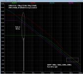
Ahh yes, in the end similar unity gain bandwidth, but indeed the AD825 starts out low.
Reminds me of the discussion that flat OL bandwidth in an (op)amp is a Good Thing. I never agreed to that, and this confirms it.
They all have similar gain at 20kHz, so in an audio application, similar feedback factor at 20kHz, so similar distortion suppression at 20 kHz.
But except for the AD825, they have increasing distortion reduction with lower frequencies. The distortion reduction by the AD825 at 1kHz is the same as at 20kHz, but the others have several 100 times more distortion reduction (or ripple suppression) at 100Hz, although their OL roll-off starts much earlier than the AD825.
Thanks for that plot Mark!
Jan
What is the regulator Zout when using the AD825? It looks like it might be invariant across the audio band. Does this affect the sound of an audio circuit powered by the regulator?
Well, it may be flat, but the others make it go even lower with decreasing frequency. So at 100Hz where the main ripple is, the others have more ripple reduction than the '825. Mark is absolutely right there.
There is no inherent advantage in being flat. Unless it is the amps freq. response ;-) .
Jan
There is no inherent advantage in being flat. Unless it is the amps freq. response ;-) .
Jan
There are lots of ways to get ripple reduction. You skipped my first question and pretty much disregarded the second question with no real evidence one way or the other. Not looking for a fight etc. 😀
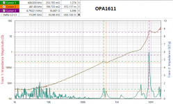
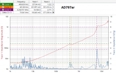
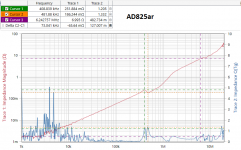
Here are some charts using the Bode-100 VNA and J2111A current injector -- a different setup from that used in the LA article (Bode-100 makes life easier). The OPA1611 would appear worse than the AD797 with regard to stability. The AD825 is no problem.
Q is derived from tg.
Q is derived from tg.
Attachments
There are lots of ways to get ripple reduction. You skipped my first question and pretty much disregarded the second question with no real evidence one way or the other. Not looking for a fight etc. 😀
I think I answered the first Q implicitly. If you have an opamp that gives more ripple reduction it will make the amp-to-be-powered cleaner. Whether you can hear that is another kettle. I hope you don't need me to 'proof' such basic stuff?
What was the 2nd Q?
Edit: I think I swapped the Q's. Answer to 1: yes, I would expect the 825 to have a flat Zout in the audio band, IF the opamp was all that counted. The other gain element in the loop is the pass device fed by the current source. Both can be expected to deteriorate with frequency, so Zout will still rise with frequency. I believe jackinnj's graphs show that.
But I would expect the Zout rise with frequency be lower or start at a higher frequency with the other opamps.
Jan
Last edited:
Here are some charts using the Bode-100 VNA and J2111A current injector -- a different setup from that used in the LA article (Bode-100 makes life easier). The OPA1611 would appear worse than the AD797 with regard to stability. The AD825 is no problem.
Q is derived from tg.
Thanks Jack for your excellent measurements. I noticed that both AD797 and OPA1611 have much slower slew rate (and therefore much longer settling time) than the AD817 (BJT) and AD825 (JFET) opamps, which have proved stable for Super Regulator. I wonder if that characteristic is the important factor in choosing OpAmp for SR.
I think among newer OpAmp, OPA828 is probably a better choice with slew rate is around the same as AD825, settling time is slower (120ns) but not too much. Noise both voltage noise and current noise is better than AD817 and AD825.
I don't see slew rate figure in this, as the opamp output moves only a small fraction of a volt.
Jan
Jan
15V Avol for ad825 rev g is 76dB
My read for the ad825 ds is 76dB for Av(ol), for +/-15 rails. Were you using the part 5v data?
If the reg Z(ol) is 1 ohm, the closed loop Z(o) will be around 150uohms (1/6500). This seems to be about what a good current day SR can do. Why do I say that? I just recently measured Z(o) to be roughly that, but limited by the noise of the test setup, as working with a dynamic load of 100mA. More on this shortly.
It is worthy of note that a SR running with a dh44 pass device may need some additional loading to get the open loop Z down. I am running my preamp at more than 100mA total (each rail) for that reason (even though the active stages are lower drain).
All that being said, I am one observer that feels the regulator Z is a very important spec.
Walt Jung
Remember that AD825's datasheet promises only 66dB (2000X) of open loop gain. Its sister products AD744, AD797, and LT1128 all have considerably higher datasheet guaranteed open loop gains: 106dB, 126dB, and 137dB respectively. If you want gigantic ripple reduction numbers (a/k/a PSRR a/k/a line rejection), pick an opamp with gigantic open loop gain.
My read for the ad825 ds is 76dB for Av(ol), for +/-15 rails. Were you using the part 5v data?
If the reg Z(ol) is 1 ohm, the closed loop Z(o) will be around 150uohms (1/6500). This seems to be about what a good current day SR can do. Why do I say that? I just recently measured Z(o) to be roughly that, but limited by the noise of the test setup, as working with a dynamic load of 100mA. More on this shortly.
It is worthy of note that a SR running with a dh44 pass device may need some additional loading to get the open loop Z down. I am running my preamp at more than 100mA total (each rail) for that reason (even though the active stages are lower drain).
All that being said, I am one observer that feels the regulator Z is a very important spec.
Walt Jung
@WaltJ
Is 100mA a target then? Scale the load resistor to bring up the current to 100mA for each rail?
This helps the regulator source and sink as well, no?
Also... mount the load resistor at the regulator or make room for one on the board of the circuit being powered? The sense line might like the former better?
That's exactly the question I was going to ask.. Is there an optimum position for this load resistor?
This R is just a DC load
Let me clarify on this Rload, it is just a DC load, thus it can be anywhere convenient. I used the 5W “concrete case” types. Yes, because of the extra Iload on the reg, it will be more capable of absorbing current. If that was ever an issue.
However, you may need to carefully check the heat sinking on the pass xstr, to make it is low enough for thermal R, to accommodate the extra loading.
Walt Jung
@WaltJ
Is 100mA a target then? Scale the load resistor to bring up the current to 100mA for each rail?
This helps the regulator source and sink as well, no?
Also... mount the load resistor at the regulator or make room for one on the board of the circuit being powered? The sense line might like the former better?
Let me clarify on this Rload, it is just a DC load, thus it can be anywhere convenient. I used the 5W “concrete case” types. Yes, because of the extra Iload on the reg, it will be more capable of absorbing current. If that was ever an issue.
However, you may need to carefully check the heat sinking on the pass xstr, to make it is low enough for thermal R, to accommodate the extra loading.
Walt Jung
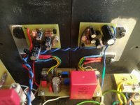
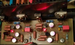
superreg no light led NEG side
Good morning to you.
I am Giampiero from Rome (Italy), I would need a little help as I am quite inexperienced on the subject.
I have completed the construction of the Superreg from DiyAudio (!) But during the connections I must have done something (some trouble ..) or everything works, I can listen to music correctly with the BA-3 to which it is connected but on the "NEG" side the LED does not light up while on the "POS" side it is on.
what should i check? what have I done?
thank you so much
(sorry my bad english)
My read for the ad825 ds is 76dB for Av(ol), for +/-15 rails. Were you using the part 5v data?
Oops! Yes I was looking at the spec page for ±5V supply rails. Thanks for the catch and apologies for the error.
Walt, I just bought a nice Chinese LCR meter that measures ESR down to one milliohm after calibration; it's the ET4510 from East Tester
I used it to measure the ESR of a few electrolytic capacitors which call themselves "low impedance" on the manufacturer's datasheet, AND which include a 100 kHz measured value of impedance or ESR on the manufacturer's datasheet.
Regrettably, Mouser didn't have every possible SKU in stock and on the shelf, the day I bought capacitors. Similarly, different manufacturers sometimes have different "holes" in their product lines; they don't sell every possible E12 value. So I did the best I could, to take data for two capacitance values (47uF and 100uF) at two voltage ratings (50V and 63V). Here are my results:
It's not a huge shock that the measured values differ from the datasheet values for these capacitors. Close study of their datasheets reveal that impedance is tabulated, not for each capacitor, but rather for each can size. Since one can size often holds several different capacitance values, they probably provide an average (I imagine).
A couple tentative conclusions:
I think if you compare the datasheets of the Panasonic "FR" caps (tested above) against their "FC" caps (not tested), you'll find you strongly prefer the FR.
_
I used it to measure the ESR of a few electrolytic capacitors which call themselves "low impedance" on the manufacturer's datasheet, AND which include a 100 kHz measured value of impedance or ESR on the manufacturer's datasheet.
Regrettably, Mouser didn't have every possible SKU in stock and on the shelf, the day I bought capacitors. Similarly, different manufacturers sometimes have different "holes" in their product lines; they don't sell every possible E12 value. So I did the best I could, to take data for two capacitance values (47uF and 100uF) at two voltage ratings (50V and 63V). Here are my results:
Code:
     DC voltage   Capci-                      MJ measured ESR    ESR value
     rating       tance   Mfg    Part number  value on ET4510    on datasheet
     -------------------------------------------------------------------------
       50 V       47 uF   Nichi  UPJ1H470MED       0.498 R          0.420 R

       63 V       47 uF   Nichi  UPJ1J470MPD       0.563 R          0.370 R

       50 V       47 uF   Pana   EEU-FR1H470       0.108 R          0.140 R

       63 V       47 uF   Pana   EEU-FR1J470       0.118 R          0.140 R

       50 V       56 uF   Nichi  UHD1H560MED       0.104 R          0.140 R

       50 V      100 uF   Pana   EEU-FM1H101       0.066 R          0.092 R

       50 V      100 uF   Nichi  UPJ1H101MPD       0.168 R          0.210 R

       63 V      100 uF   Nichi  UPJ1J101MPD       0.170 R          0.200 R

       50 V      100 uF   Nichi  UHD1H101MPD       0.055 R          0.074 R

       63 V      120 uF   Pana   EEU-FS1J121       0.050 R          0.063 R

       50 V      100 uF   Pana   EEU-FR1H101       0.067 R          0.092 R

63 V 100 uF Pana EEU-FR1J101 0.053 R 0.063 RA couple tentative conclusions:
- The Panasonic "FR" and the Nichicon "UHD" seem to be tied for first place. Panasonic "FS" (smaller) is also good, but there are very few capacitors in the FS product line
- Panasonic's datasheet appears to be more conservative than Nichicon's; measured ESR of Panasonic FR caps is always lower than the datasheet value. Whereas measured ESR of Nichicon UHD caps is usually higher than the datasheet value. So if all you have is a datasheet and not a sensitive ESR meter, buy (and trust) the FR.
- The apparently small increase in working voltage, from 50V to 63V, sometimes has an effect upon ESR. Be prepared to use the 50V and not the 63V, if its ESR is much better.
I think if you compare the datasheets of the Panasonic "FR" caps (tested above) against their "FC" caps (not tested), you'll find you strongly prefer the FR.
_
Last edited:
I should add that I was looking for electrolytic capacitors with the lowest possible ESR. Walt may want a certain specific range of ESRs (for stability), which may not include the very lowest. One way to get a certain specific value, or a certain range of values, is to test a bunch of capacitors and pick the ones which have just the right ESR for stability. Another way is to use a Panasonic FR capacitor, trust its datasheet value of ESR (which will be quite low), and then add a discrete resistor in series to bring the total resistance up to the designer's optimum value.
_
_
Last edited:
Does ESR matter when it is across 1 mohm Zout?
Thanks for all the ESR data Mark. That meter does sounds very useful.
But, after my long and arduous exercise of testing those caps and seeing really, NO significant difference in the time domain display, I'm left to wonder about how critical ESR is to a SR ckt. Yes, one definitely needs an output cap, but the value and ESR don't seem highly critical. The output cap is really a Zobel network.
My view is that the extremely low shunt Z value of the reg works to minimize the sensitivity to cap ESR. Like, if Z(cl) <1mohm why should it matter if ESR is 100mohm or 0.39ohm? ... example values from my tests, for whatever that's worth. They all work, as was my experience with the several builds.
But I do agree with you that the Panasonics lytics are good for low ESR.
I have always used panasonic FC in my SRs, but in my 4A current version of SR I used Rubycon ZLJ for the first time as well as 100uF OS-CON on the + input pin of the AD825. The ZLJ series sounded better than the FC series. Now with this high current SR I supply Hiraga Le Monstre with +/- 19V.
For digital circuits I made UnivReg_122714 and there I put all 100uF, 16V OS-CONs that have 24mΩ at 100kHz. I did not notice any problems in the work, on the contrary it is the best regulator I have made for digital. I am using an AD817, for a 2.5V reference ADR525 which now goes to + 5V via CCS instead of a 2.49K resistor.
I also made a - version per template from - version of Improved_PN_Regs because in this case I couldn't use a transformer with two separate windings to get +/- 5V.
Attachments
- Home
- The diyAudio Store
- Super Regulator