 A new thread has been split from this one. Please see:
Yes but you ALSO need an input voltage for the negative side!
Let us say you need 20V input for 15V out, then you need:
+20 -- gnd -- -20.
That can be two separate supplies like the 317 you show:
+20 -- gnd
gnd -- -20
Or a single +/-20 with center ground: +20 -- gnd -- -20.
Jan
Let us say you need 20V input for 15V out, then you need:
+20 -- gnd -- -20.
That can be two separate supplies like the 317 you show:
+20 -- gnd
gnd -- -20
Or a single +/-20 with center ground: +20 -- gnd -- -20.
Jan
Ok I think I understand.
now i try to do that and i will let you know soon.
thank you so much for your patience.
See you soon.
Giampiero
now i try to do that and i will let you know soon.
thank you so much for your patience.
See you soon.
Giampiero
That is a very nice comparison, thanks for that!
Clearly the 825 is not the best choice based on this data, although I must admit I have almost exclusively used it because it always works as expected, never have seen any instability or other issue.
So, what would be your own preference now? Have you tested any in hardware?
Jan
Thanks Jan,
Unfortunately no hardware testing yet, but it will come hopefully.
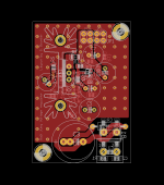
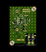
A lot of simulations though, and a PCB ready to be populated (for personal use, see attached). I went with my own design to be able to experiment with more modern components (like the zener reference), adding the possibility to add components for stability or higher current, and use of smd with very compact layout to allow good performance and close placement to the load. Maybe it will be a success, maybe it will fail dramatically 🙂
Coming back to the opamp:
On paper, obviously the ths4031 looks great, especially at HF.
The opa1611 is a very good compromise in terms of low noise, high OLG, good phase margin, and price (and field proven now!). Stellar performance in sims as expected.
lm4562 (i.e. lme49710 duals) is decent but not great phase margin.
ADA4851 looks very good if you don't mind the higher noise.
For a reasonable application to audio with duals rails, I like a lot the new opa2210. Very similar to the older opa209, which was almost perfect except a high susceptibility to RF, which I think was fixed in this new version.
Sam
Attachments
Last edited:
Pin 3 doesn't tell me a lot, there are many confusions in data sheets from manufacturers. That's why I asked for Vcollector.
Anyway, the input at DCin goes directly to the collector. Measure the DC negative input voltage against ground, (pin 1 of J5 against pin 2 of J5), and the collector voltage against ground (collector is where Q3 connects to R8) against pin 2 of J5.
They should be the same, we want to first make sure that the input voltage is getting on the circuit.
Jan
good morning Mr. Didden.
I did what I had to, pin 1 of J5 against pin 2 of J5 = -20.5V and (-DCgnd) against collector Q3 (middle pin) = -20.6V but the led is still off.
A strange thing: while taking the measurements, I inadvertently touched R8 and R9 between them and for a moment the led turned on.
Why?
thanks a lot again
I would think that is an indication that R8 and/or R9 are not right soldered.
Do you see in the schematic that R9 and the LED should be on the 20.5V? So why is the LED not on? What is the voltage across R9, what is the voltage across the LED?
You'll get a long way with reasoning - look at the schematic, where the voltages are, then check on the PCB.
Jan
Do you see in the schematic that R9 and the LED should be on the 20.5V? So why is the LED not on? What is the voltage across R9, what is the voltage across the LED?
You'll get a long way with reasoning - look at the schematic, where the voltages are, then check on the PCB.
Jan
Last edited:
I was surprised by Walt's comments here, which apparently have to do with this design sold here.
Testing for SuperReg-2020
Or did I misunderstood his words?
He wrote several times on this thread.
Testing for SuperReg-2020
Or did I misunderstood his words?
He wrote several times on this thread.
That wasn't clear either.
My impression was that it was just the current tweak of the old design.
Again, some clarity would be nice.
My impression was that it was just the current tweak of the old design.
Again, some clarity would be nice.
Why isn't anybody commenting anything on Walt's thread? I think it has some suggestions to improve the SR.
Hi Jan,
I am building the superreg for 3 voltages, +5, +24, and +/-18. This is my first DIY project and I have a few questions.
1. Is LM329 still the best for the 18V output? I can calculate the resistors, but I have a hard time finding an equivalent diode for 9V.
2. Same question for the 24V output. Can you please recommend a 12V diode or is LM329 still the best?
3. For the 5V output, your article metions LM4040 and AD817, which are fine. Should there be any other changes aside from the obvious input voltage, voltage reference resistors and zeners?
4. On the zeners, I find only 0.5W versions, I hope this is fine instead of 0.25W. Do you recommend any particular type or brand of zeners?
Thanks so much for your help!
Alex
I am building the superreg for 3 voltages, +5, +24, and +/-18. This is my first DIY project and I have a few questions.
1. Is LM329 still the best for the 18V output? I can calculate the resistors, but I have a hard time finding an equivalent diode for 9V.
The reference is not critical as long as you know how to calculate the feedback resistors. For 18V, the LM329 is fine.
2. Same question for the 24V output. Can you please recommend a 12V diode or is LM329 still the best?
Same comment as for 18V
3. For the 5V output, your article metions LM4040 and AD817, which are fine. Should there be any other changes aside from the obvious input voltage, voltage reference resistors and zeners?
Not really. For an output of 5V, obviously the '329 cannot be used. The 4040 is a good alternative, and the 4040 is also available in 5V, 8V, 10V, so can actually replace the LM329 in other versions too.
4. On the zeners, I find only 0.5W versions, I hope this is fine instead of 0.25W. Do you recommend any particular type or brand of zeners?
0.5W is fine, but check wire diameter versus PCB hole diameter. No specific recommendation, but if you have a choice select those with lowest zener impedance. But that is not easy as the datasheets often specify it at different operations. My experience is that modern small level zeners are basically all the same.
Jan
Great, thanks Jan! Sorry, I forgot to ask about the transformer. What is a disadvantage of the center tap? Most transformers I find have it. Is it worth looking hard for separate secondaries? Thanks again!
The advantage of separate secondaries is that you can keep the two grounds for the pos and neg reg separate until at the very end after the regs or even at the load.
That makes it easier to keep the grounds clean.
With center tapped secondaries you don't have that option but the effect may be minimal. If you already have a CT xformer I would go with that first and if there are no obvious problems, you're done.
Jan
That makes it easier to keep the grounds clean.
With center tapped secondaries you don't have that option but the effect may be minimal. If you already have a CT xformer I would go with that first and if there are no obvious problems, you're done.
Jan
Got it, thank you Jan! So, on zeners' impedance, as an example, for the 24V output, which of these would be best: 6.8V/3-Ohm or 7.5V/4-Ohm or 9.1V/6-Ohm or 12V/7-Ohm?
For 24V a zener value around 12V would be fine. My earlier comment was to a zener to be used as a reference, but if you are talking about the zener in series with the opamp output the zener impedance is pretty much irrelevant - it is within the feedback loop.
Jan
Jan
- Home
- The diyAudio Store
- Super Regulator