Good morning to you.
I am Giampiero from Rome (Italy), I would need a little help as I am quite inexperienced on the subject.
I have completed the construction of the Superreg from DiyAudio (!) But during the connections I must have done something (some trouble ..) or everything works, I can listen to music correctly with the BA-3 to which it is connected but on the "NEG" side the LED does not light up while on the "POS" side it is on.
what should i check? what have I done?
thank you so much
(sorry my bad english)
Do you have a multimeter? If not, you should get one. Then you can do some measurements to find out what the issue is.
Jan
So, with the multimeter, first check the two output voltages. Are they +/-15V?
If the neg voltage is not correct, measure the voltages on the opamp input pins for that regulator, and report back.
Jan
If the neg voltage is not correct, measure the voltages on the opamp input pins for that regulator, and report back.
Jan
Do you have a multimeter? If not, you should get one. Then you can do some measurements to find out what the issue is.
Jan
OK thanks!! I will carry out the checks and report ..
So, with the multimeter, first check the two output voltages. Are they +/-15V?
If the neg voltage is not correct, measure the voltages on the opamp input pins for that regulator, and report back.
Jan
the voltages are 13.52V but I have now found that the D45H11 (Q3) is frozen, cold (!) while the D44H11 (Q1) is (rightly) hot and the led is on.
the voltages on pins 2 and 3 of the opamp are: 0.6V on the POS side and -0.1 on the NEG side
thanks Giampiero
Are you saying that the neg voltage is also 13.xx?
Can you check the connections on the two sense lines for the neg regulator, are they connected?
Also check that the input voltage is present at the collector of the pass transistor
Jan
Can you check the connections on the two sense lines for the neg regulator, are they connected?
Also check that the input voltage is present at the collector of the pass transistor
Jan
Walt,
Thank you for the article.
Would you also be published the tester schematics some time ?
Best regards,
Patrick
Thank you for the article.
Would you also be published the tester schematics some time ?
Best regards,
Patrick
corrent collector of the pass transistor: -7.1V
Giampiero
So there is a problem. The collector is directly connected to the input voltage. How much should the input voltage be? Check that connection.
How much is the negative output, I guess very low or zero?
Jan
Ok, but should i measure between -DCin or -DCgnd? and pin 3?
between -DCin and pin3 D45H11 is 09.3V
between -DCgnd and pin3 D45H11 is -6.2V
thanks
Giampiero
between -DCin and pin3 D45H11 is 09.3V
between -DCgnd and pin3 D45H11 is -6.2V
thanks
Giampiero
Op-amp choice
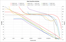
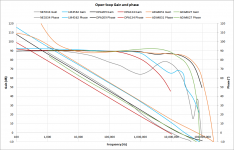
Following the discussion regarding choice of op-amp for the super-reg, I compared a while ago characteristics of a selection of potentially best candidates for the job, along with the usual suspects. Opamps were selected for both high open-loop gain and high phase margin.
Following the discussion regarding choice of op-amp for the super-reg, I compared a while ago characteristics of a selection of potentially best candidates for the job, along with the usual suspects. Opamps were selected for both high open-loop gain and high phase margin.
Attachments
0.93Volts, sorry
Pin 3 doesn't tell me a lot, there are many confusions in data sheets from manufacturers. That's why I asked for Vcollector.
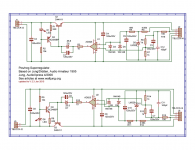
Anyway, the input at DCin goes directly to the collector. Measure the DC negative input voltage against ground, (pin 1 of J5 against pin 2 of J5), and the collector voltage against ground (collector is where Q3 connects to R8) against pin 2 of J5.
They should be the same, we want to first make sure that the input voltage is getting on the circuit.
Jan
Attachments
Last edited:
Pin 3 doesn't tell me a lot, there are many confusions in data sheets from manufacturers. That's why I asked for Vcollector.
Anyway, the input at DCin goes directly to the collector. Measure the DC negative input voltage against ground, (pin 1 of J5 against pin 2 of J5), and the collector voltage against ground (collector is where Q3 connects to R8) against pin 2 of J5.
They should be the same, we want to first make sure that the input voltage is getting on the circuit.
Jan
OK, pin 1 of J5 against pin 2 of J5>7.1V
and collector against pin J5>0.0V
I guess that is : ... collector against pin 1 of J5>0.0V? Please be specific, otherwise it's hard for me to know what's going on.
Also, remember that '>' means 'greater than'. I don't think that is what you meant.
OK, so now you know that the required negative input isn't there. Therefor, the regulator cannot work.
I assume you have a rectifier and such to make that negative input? How does that circuit look, can you post a pic?
Jan
Last edited:
ok I'm sorry you're absolutely right I wasn't precise.
I am attaching a photo, the R8 is soldered under the pcb because it touched the heatsink so you can't see it and I removed the heatsink to make the measurement more comfortably.
thanks for your patience!
I hope the photo is clear!
I am attaching a photo, the R8 is soldered under the pcb because it touched the heatsink so you can't see it and I removed the heatsink to make the measurement more comfortably.
thanks for your patience!
I hope the photo is clear!
Attachments

Following the discussion regarding choice of op-amp for the super-reg, I compared a while ago characteristics of a selection of potentially best candidates for the job, along with the usual suspects. Opamps were selected for both high open-loop gain and high phase margin.
That is a very nice comparison, thanks for that!
Clearly the 825 is not the best choice based on this data, although I must admit I have almost exclusively used it because it always works as expected, never have seen any instability or other issue.
So, what would be your own preference now? Have you tested any in hardware?
Jan
ok I'm sorry you're absolutely right I wasn't precise.
I am attaching a photo, the R8 is soldered under the pcb because it touched the heatsink so you can't see it and I removed the heatsink to make the measurement more comfortably.
thanks for your patience!
I hope the photo is clear!
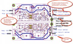
So where is that white ground wire going to? I only see one feeding 317 power supply, how do you make a separate pos and a neg input??
Jan
the white wire is GND on the chassis.
But then I have some connection wrong?
the white cable is not connected to 317 .. I must have made a mess I know !!!
I do not want to waste your time but I have collected here and there on the connections to make but sure I was wrong.
I am attaching example of how I made the connections.
But then I have some connection wrong?
the white cable is not connected to 317 .. I must have made a mess I know !!!
I do not want to waste your time but I have collected here and there on the connections to make but sure I was wrong.
I am attaching example of how I made the connections.
Attachments
- Home
- The diyAudio Store
- Super Regulator