Philips CD202 no sound 🥵

Hi,
Not my first player of that generation (1983). I’ve already done quite a few over the years.
But that one… 😓

Does anybody here know what the issue might be?
This is a SO-PHI model.
The reed relays are fine.
CDs are read but no sound – it worked just a week ago!
The player has just been repaired by myself. Prior to repairs, the player didn’t play anything, didn’t display anything.
I have the full service manual, checked everything on the oscilloscope and yet no sound (both channels).
Eye pattern looks absolutely perfect, if you are wondering, and all functions work.
All I can hear is a click when track changes.
Op-amps are fine.

Any leads welcome.

Thanks for looking! This picture was shot before the repairs. DIL sockets have also been replaced.

B69A8571-00D2-4A0E-A53B-0C0968B065BF.jpeg

Hip4080

I have an amplifier that makes a noise without you connecting the rca, initially the mosfet and the hip4080 were burned, then they were replaced and I am left with that noise, I do not have an oscilloscope to make measurements, I was reading in some threads that replacing the irf3710 with the irf3710z the problem is corrected. someone help me to find the error

Black Gate NX HI-Q 6.3v./ 22mfd. for sale

I have 8pcs. of the NX HI-Q 6.3v./ 22mfd. left. They're for sale on Ebay. https://www.ebay.com/itm/125037855918

I have a few other Black Gates, some New Old Stock, some were removed from circuit boards for projects that weren't completed, therefore never really "used'.
I sell on Ebay as it protects both the buyer and seller. I don't like Ebay, but it's safer and I've had a lot of overseas buyers. Ebay's Global Shipping works out best for selling outside the USA. Check out my other auctions for more Black Gate's. All are authentic Rubicon Products purchased back in 2009 from Parts Connexion. Too many to list them all here. Thanks

PE wiring with Star Ground

Hi,

I'm just seeking some clarification with the wiring of my SMPS with the protective earth and star grounding.

Question 1) I know that the earth from the IEC socket should connect to the chassis with a short wire, but should the Earth connection on my SMPS (LRS-100-36) go direct to the eic earth, or both meet at the same chassis point?

Question 2) I have 2 grounds on my PCB (pwr & aud) which come back to a star ground. Is it ok to bring them back go the chassis point with PE, or should they go to a separate point on the chassis?

Im using 17awg wiring for the 240/10A ac.

Is the attached correct or does it need a change? (ps i have covid and took about 4 hrs to write this. sorry if its a bit jumbled!)
wiring.png

Attachments

Top Cap Adhesive.

One of my 866A tubes lost it's top cap. There is some sort of friable brown spongy material under the cap. I've crimped on a piece of wire (couldn't solder to the tube pin) to the piece sticking out of the tube and will solder that wire to the cap but I'd like to use some sort of adhesive to support things. The temperature is pretty moderate at less than 50C. I was thinking some RTV adhesive but what would you folks recommend?

What's causing the "pop". Mixer input mutes.

Hi,

Im having trouble with switch pop noice when I active channels. Its a big mixer with 20 stereo inputs and 12 mono.. The schematic only shows the four first inputs on the left side but you get the idea. I wanted to leave out all the 20K resistors when they are not in use to minimize the noice from them.. (there is a lot of them with 32 inputs..) therefore I placed the switch after them. The pop noice is only present first time I activate the channel.. If I mute the channel then active it again the switch pop is gone... Same goes for all channels the pop is only there the first time I switch.

Any ideas how the make the "pop" go away?

The mixer is used with keyboards/synthesizers.

Key_Mix_1.png

Status of tube shopping (new production).

I know this thread is likely going to be locked if people don't keep it objective to the end result of the current situation (not here to talk about the situation, just the impact in tubes and likely on New Sensor, not sure if there are other relevant factories in the region), but it appears most retailers have increases retail prices in the past week AND many are sold out/backordered (with a status TBD) on top of those price increases. I know there are some factory options in other nations, but not sure of the quality, capacity, etc. NOS is not an option for many tubes (or vastly more expensive). Going to be interesting.

Tube Preamp ground lift using Bridge resistor and cap?

I`m just getting very faint ground loop. I have used chassis ground directly from the B+ Gnd. Now getting low level ground loop with 98db sensitivity speakers. Finally thinking to add a Bridge block rectifier 50A with + and - short use a 100 ohm resistor across AC inputs of the bridge and connect the AC terminal of the bridge to B+ Gnd and other to chassis earth just like how we usually do with amps. Now how far is this right when it comes to preamp. I`m using 6sn7 in Mu follower configuration.

Do I need to get the RCA -ve returns to B+ Gnd directly? instead of the on the preamp board signal ground?

Attachments

  • image_2022-03-18_002335.png
    image_2022-03-18_002335.png
    2.8 KB · Views: 600

Collecting Sony VFETs (2SJ28, 2SK82, maybe others) for curve matching and distribution on diyAudio

After all the craze about the Sony VFET parts (2SJ28, 2SK82, etc.) I had this wild idea of collecting as many of these parts as possible, run them through the curve tracer for testing and matching, and then make them available here on diyAudio. (See here why curve matching may be better than simple Vgs matching.)

I currently have 20 Sony parts which I don't need for my own amps, and there are more on the horizon. The more parts there are, the better for the matching, and the better for those in need of these parts. 🙂

My idea of making this work is as follows:
  • People sell their VFET parts to me at a reasonable price (yes, I have some money that I can borrow). Send me a personal message (PM) if you have some Sony VFETs.
  • I will also accept previously untested parts, parts that may not work properly, or parts of unknown sources (as long as I am sure I can get a refund for bad parts).
  • Once there are enough parts in the collection, people can start getting matched parts. The price will be such that it covers the average price I payed to get the parts plus a small fee that helps to keep me motivated.
  • People may also send their parts to me and get matched parts in return (for a small matching fee).
Before actually kicking this off, I'd like to get some feedback and comments on this idea. What do you guys think?

TINA spice simulation gives floating warnings

Hey guys!


I'm trying to simulate a simple mic preamp with TINA. Here's the circuit I'm using.


So I created a simulation, here it is.


When I run ERC Analysis it's all green. But when I run DC Analysis -> Table of DC Results, I get 2 warnings:

- Pin 1 of Voltage Pin Vout is floating

- Pin 2 of capacitor C3 is floating.


I tried to change that part multiple times but no luck.

Please help me out here.

Thanks!

THAT1646 vs op-amp based differential line driver

I have used the THAT1200 in projects to reject common-mode noise for balanced input. I can understand the need to use a specialized part for this purpose, as a differential receiver might require something like laser-trimmed resistors on chip to achieve high common-mode rejection.


However, there is also the THAT1646 which is a balanced output driver. Is it necessary to achieve extremely low common-mode signal on a differential output? I was thinking of a simpler solution like driving the output with a NE5532 unity positive gain and unity negative gain amplifier. The resistors would not necessarily be perfectly matched so the gain of both would not be exactly equal (probably with 1 to 2% or so I would guess), but since this difference is likely to be small and so the common-mode that is generated is likely to be small and should cause very little rejection of the audio signal at the receiver.


Or is there another reason why it is important to achieve a very balanced output that I am missing here? I would just like to avoid using a specialized part unless there is a significant benefit.

Tweeter source for mic calibration

I have ordered a couple of ND20FB-4 tweeters in order to perform second teir calibration of MEMS mics using a known microphone for the range >2kHz. The idea is that I will put the tweeter on a flat baffle placed on the floor, position the micrphones in exactly the same point in space above the tweeter and perform gated measurments in order to calibrate them. I used Vitux-cad diffraction simulator to come up with this baffle design:

1646093371933.png


I think the ripple ~5kHz will not occour as the tweeter will not be omi at this frequency. Any comments? I haven't seen anyone calibrating microphones with this kind of source before so could be making some silly mistakes.

Rockford 60 DSM

Repaired a 60dsm. It had obvious leaky caps, and overheated and ejected one of the 150ohm 2w resistors on the speaker outputs. Also replaced the LM833 opamps on the preamp riser since I had it out and had past experience of them damaged by the leaky caps. Nothing else seemed damaged in the output stage.

Amp seemingly works fine and drives above rated power, but bias pots ended up at about 10:00 and 12:00 setting them via 5mA draw. Usually they are closer to the same position. Found that one 2k bias pot read 2120ohm and the other 1842ohm. Swapped the 1842ohm for one that was about 2150ohm with no real change in the resulting position.

Should I be concerned about the difference?

Totem Hawk cabinet

Hi everybody, i have a pair of bookshelf speakers i made long time ago, based on a Troels Gravesen design. They are based on ScanSpeak 15w/8530 k01.. same woofer used in the old Totem Hawk.. I would like to try a different cabinet.. floorstander... and i was guessing if anybody knows Hawk cabinet details, volume and port dimensions, and something on stuffing.. tx in advance

First time slot loaded build, Sanity check

Hello all, I'm just looking for a quick sanity check on a proposed build.

For a little background, here were some of the constraints:

Footprint of 26.75" by 37.7" so it can support an Altec 817a cabinet. It does bring the benefit of bringing the HF horn of the system (Altec 291) near ear level and centered from the floor and wall. I could place the subs to the side but it would require moving furniture and reconfiguring the listening area.

Designed for a pair of JBL 2242h. I know its not the best "sub", if you can even call it that, but I have been building systems from public surplus parts I have acquired because they do bring good performance for the money. 100% for music listening so no need for HT level of low bass, the 817a "extend" down to 80hz according to Altec but that is more of a -6 db point, -3 db is probably 140hz. So looking for a response around 30 hz to 140 hz for the sub. I have a mini dsp and a fully active system so I have some variability on setup.

So with those constraints, I was targeting something similar to the JBL 4645C (8CF, tuned to 25 hz, +6db boost at 25hz q=2, 2nd order highpass at 25hz). Wanted to put slotted ports on the sides with a 2x4 in the middle to add bracing (so 4 ports total), and the port running the full height of the enclosure. That wasn't looking promising so I found a compromise using 3/4" MDF on the sides for 6 ports. This leaves a 9CF box with all the same parameters for the 4645C. I know the shortcomings of the design would be the 2242 will not be able to hit max power handling before running out of Xmax and setting the delay for the system will be an issue. But within Xmax gives around 114db (iirc) at 1m without boundary gain or gain from the second speaker, so more than enough output for me.

I plan on lining the cabinet with rockwool, except the back 45 degree wall that shares with the port (would the rockwool interfere with the port?). The dimensions didn't print, but the port end is 4.25" away from the back wall. Using 2x4 to brace the cabinet between the ports and 1/2" dowel rods from front to back.

I have designed sealed and ported subs with tube ports, but the is a first for a slotted port design. So, I'm just checking to see if there are any critical flaws.
sub response.png

Attachments

  • sub.png
    sub.png
    6.1 KB · Views: 109

amplificador phoenix gold octane r 15.0 1

I have an amplifier that makes a noise without you connecting the rca, initially the mosfet and the hip4080 were burned, then they were replaced and I am left with that noise, I do not have an oscilloscope to make measurements, I was reading in some threads that replacing the irf3710 with the irf3710z the problem is corrected. someone help me to find the error

Dark Days at Bose

https://www.thelayoff.com/bose

"I was with Bose for 13 years, and some of the poor decisions the company made, paved the way for where it is now.

The surround sound TV. When this was announced myself and quite a few coworkers were in shock at this decision. TV technology changes almost every year and to think that consumers would buy a 5k 42” TV, just showed the lack of market knowledge. I was standing next to my manager during this announcement and told him this was a mistake. He didn’t agree. When it was finally announced that we’re not going to make or sell them, I believe the total number sold was 5.

Building a manufacturing facility in Malaysia. This was the worst decision ever. When this was announced I told 3 of my closest buddies that in less than 5 years we would sell it. We should’ve outsourced the work to one of the many CM’s in Malaysia instead of spending millions on building a facility from scratch. And no I’m not playing Monday morning QB. More people felt the same way but were afraid to talk because it meant that the leadership didn’t know what they were doing.

And here’s another example of money being wasted. The extra +/- 100k (not sure on the exact figure anymore) given to the architect to make our logo resemble a dragon. When this was presented, everyone in the conference room looked at each other in disbelief and started laughing. Every time I and many others visited the facility, the joke was “did you see the dragon yet?”

The millions spend on this facility could have been used in R&D and market analysis."
  • Thank You
  • Like
Reactions: head_unit and GM

Question regarding phase differences of amps.

Hi all,

I was thinking about this yesterday and couldn't find any other threads that answers my question.

Given that each element in a crossover shifts the phase, as does each op amp in an amp, do different amps have different group phases when all elements are taken in to account?

Different amps will have different amount of components in them, and if the crossover is passive/after the amp this doesn't really matter.

But if you have an active system with a different amp for each band, surely that could cause big differences in the phase of each section?

Thanks, Will

perry babin i need your help! hifonics brutus bxx4000.1d blown capacitors, replaced, still in protect. guessing driver board ?

sorry everyone i tried to keep the title short and descriptive.

years ago perry babin helped me so much he is the man! would be willing to send donation like last time if we can fix board or to whomever helps me!

board: Hifonics brutus BXX4000.1d (yes the old version that is discontinued now)

Protect mode: yes

there were two blown 10uF 250v 105C capacitors, i replaced them both with same details. (the newer capacitors were slightly smaller by a few millimeters)

i could not see anymore damage anywhere else visually, i then proceeded to check the mosfets (as best i know how) with a multimeter on the ohm setting, and got .6 except for 4 fets (2 on each rail side), but they were different fets they read u30d20c and all the other mosfets that checked out at .6 read irfp064n p752d (i am guessing i am just reading or diagnosing them wrongly considering their different mosfet transistors and they are probably good?)

please let me know how i should proceed, i am assuming it is possibly some transistors on the driver board, but please assume my equipment is limited, i just have a multimeter but i am willing to buy components and replace them. my knowledge is quite limited so pictures would also help.

The green capacitor that is circled in red in the picture, i replaced both capacitors on the board like i mentioned. amp still in protect mode after replacing.

please also refer to picture of polarization to make sure i installed capacitors polarization correctly. double checking my work.

last bit of detail i can provide, the capacitors i replaced, like wow ive never seen capacitors completely blown, but the paper cardboard material in the capacitors was literally in pieces everywhere throughout the board. ive never seen a cap so violently explode before. looked like it got shot by a rifle, when i took it out there was nothing left but the rubber bottom stop and the metal connectors to it.

Attachments

  • 10uf 250v capcaitor.png
    10uf 250v capcaitor.png
    737.1 KB · Views: 517
  • polarization.png
    polarization.png
    7 KB · Views: 264
  • IMG_20220211_201939.jpg
    IMG_20220211_201939.jpg
    480.9 KB · Views: 340
  • IMG_20220211_201905.jpg
    IMG_20220211_201905.jpg
    449.6 KB · Views: 313
  • IMG_20220211_201856.jpg
    IMG_20220211_201856.jpg
    512.8 KB · Views: 337

Technics SL-1100: Possessed? (Platter rotates at power on)

I could use some brain power, as mine apparently isn't up to the task. Here's the situation: I'm working on a Technics SL-1100. When the power switch is moved to On, the platter begins spinning. Of course, it isn't supposed to do that, but rather instead wait for Start to be pressed. Once the platter is spinning, pressing Stop will often (but not always) stop it, but usually only for a few seconds, and then it will often begin spinning again. During those times when the platter stops and stays stopped, pressing Start will have no effect.

I've replaced both mini snap switches used for Start/Stop. I've also tested the following transistors in circuit, all were ok (not shorted), though I'll pull any that folks think warrant out-of-circuit testing.

TR9
TR11
TR12
TR13
TR14

All electrolytic caps tested with my Peak ESR70 Plus--nothing out of the ordinary. I checked all of the solder joints and touched up a few. In terms of voltages. I've measured around TR11, TR12, TR13, and TR14, and everything is close to what's shown on the schematic. One odd thing is that all voltages are showing negative with my common lead connected to pin 7, per the instructions in the SM.

I feel like I'm missing an obvious culprit here. . . .
Schematic.jpg

Thermal Interface - Aluminium Nitride (AlN)

I've searched through pages about aluminium nitride plates, but couldn't find someone who actually used them (we know the numbers).


There are some vendors on aliexpress and the 0.6mm ones could be promising, at least if it is AlN as stated. Anyone used AlN pads sourced from Aliexpress?
To me this seem to be the best solution performance and robustness wise (with a high performing grease, of course)

IGBT Conversions for Forte Audio Amps?

My trusty Forte Model 5 and Model 6 are starting to show their age, and during a scheduled maintenance, I found an emitter resister completely blown (more than two VOLTS across the resistor when biasing), which, of course was caused by a bad IGBT. This led me to test all the output transistors (Very nicely matched within each amp, BTW) and I found one of the model 5 transistors to be bad as well!
Both were P-channel GT20D201, which (if you can find them) are only available as used pulls for around $20 each.
Which led me to start thinking about updating the entire board(s) with newer parts, and might not cost much more. I know the circuitry was designed around the IGBTs, and I really don't want to start rebuilding that. The latest version of Toshiba's IGBT is the GT50J121, which is faster, and has a higher current and voltage rating.
That's the background, here's the question(s): has anybody ever actually changed out a full set of IGBTs with a different model? Would the output circuitry be so carefully chosen that it would only sound right with the original transistors? Or, is there anything else you have learned from experience that would be a caution here?
Thanks for sharing your knowledge!

Coupling capacitor dac.

Hi, im building a DDDac1543. Its going to a preamp with 50k input impedanc. What is the smalest output cap I can use on the dac and not loose any bass? Im looking at Solen film/foil teflon to use in dac, Im a fan of V-cap ODAM but have them as output cap in preamp and in crossover so think that is good for now. I also before have bypassed caps in signal way but dont do that anymore, dont like “smearing” of the sound, but that is just my experiance. Frank
  • Like
Reactions: analog_sa

Adcom GFA 555 power switch behavior. Need advice

I was given an Adcom GFA-555 that was reported to be not working. I checked all fuses and wiring and components visually for burned resistors bulging caps etc BEFORE plugging into the DBT. I am using a 100W bulb. When I plugged into the DBT to test the amp the lamp lit bright and slowly dimmed but not completely dim, with the power button in both the on or off position. How should I begin to proceed with this repair, and should I assume the switch is fried or that something in the amp is shorted?

New member and new to DIY!

Hello everyone, I am new to the forum and am looking for some advice where to start with building a DIY amplifier!

I have Avantgarde Duo (103dB sensitive) speakers and I currently run an Audion SET tube amp that can take 300b or 2A3 valves. I love the sound of the valve amplifier but it’s had a couple of wobbles recently that has resulted in gong in for repair.

The first time this was in for repair I purchased an Amptastic Mini-1 and while it didn’t have the wonderful musicality of the Audion I was rather shocked with how quiet it was and how fast the bass was.

This has got me thinking about building something solid state that will give me the fast bass response but hopefully match the lush musical sound of the 300b/2a3

I really have no idea where to start! I am not too shabby with a soldering iron though!

Thank you

Does anybody know anything about RCL drivers?

RCL 'made' some fairly robust budget drivers in the late 90s. I can't speak to their quality but they were pretty indestructible. Later they introduced their 'hi-fi' series of bass drivers: PP8 & PP10 with concave dust-caps. But a little birdie told me RCL never manufactured drivers - simply branded them, and the H-Fi series were made by SEAS. SEAS have an excellent reputation, and their drivers ain't cheap.

I only ask because I have acquired a pair of PP8 drivers and have cannot find any information on them.

Does anybody have any further information?

Broken Sony SRS ZR7

Hello all! I have a Sony SRS ZR7 speaker that fell the other day. Unfortunately, since the fall the speaker produces a buzzing noise when playing louder music. I have taken the grill off and noticed that there is a scratch on the thing (cone? sub?) second from the right. Seems that the buzzing is coming from that one as when I touch it when music is playing and sound no longer comes out the buzzing stops. I have tried to open the unit to no success, as even when removing all screws the front plate is really wedged on there. Does anyone have any suggestions for DIY fixes or advice on how the unit can be opened or is this the end of my dear speaker’s life? Thanks!
C6AFDFE5-8C34-471D-B070-929E960D2195.jpeg

Sinclair-Peterson based power Amp.

Works stable and sounds more than just fine with triode tubes but I`m wonder if this old OTL amp concept from early 50` is applicable for modern various J-Fets and SIT power devices ? ,
short circuit description ; Q1 is the input transistor which achieve major voltage gain and is AC coupled to Q2 gate , Q2 is phase inverter where its drain is 100% positive bootstrapped from loudspeaker output line which achieve dynamic asymmetric drive for SEPP output power pair , Q2 drain drives Q3 gate and in the same time Q2 source out of phase drives Q4 gate , P1 trim-pot regulate current via Q2 and in the same time regulate Iq of the output Q3 & Q4 SEPP power pair , B+=48V is chosen for deep A class of operation of SEPP- OPS ,
yours suggestion and critics are welcomed , guys with Spice skills also is welcomed .

Attachments

  • Sinclair Peterson J-Fet Amp..jpg
    Sinclair Peterson J-Fet Amp..jpg
    332.4 KB · Views: 209

Orion HCCA 2000.4 Problem with channel 1 and 4

This amp suffered multiple problems including failed opamps and channel 4 output TIP35/36 failures. Open base (3.3ohm) and emitter (0.1ohm) resistors. Someone previously bought ST brand TIP35/36 but likely got stuck close to where I'm stuck now. The previous repair removed all the drivers which are TIP41/TIP42, B600/B631 and 1023/1027.

I'm working on Channel 4 now. There is no bottom waveform. I tried swapping out many parts and testing parts and cannot find the solution.

Is there a schematic available for this amp by chance?

Audio signal comes in clean on the base of Q403/Q404/Q405/Q406 but then immediately gets clipped at the emitters. I swapped out FR with 3B. BR Im not sure what that is. I tried 1B transistors but the amp stayed muted.

Over/Under & Right-Sized Rectifier PS

A few expensive small-signal components utilize two rectifier tubes, including 5AR4s; each supplying one stereo channel. This sometimes includes massive filtering capacity. OTOH, most high-end power amps have only one rectifier and much less filtering. I realize this may be for marketing purposes, to some extent, for those pre & phono amps with "over-sized" power supplies. But if there are valid reasons for this, why don't more power amps use larger a PS?

Positive Feedback Meets the Amazing Circlotron

I wanted to build a variation of the Amazing Circlotron with Exicon Mosfets and positive current feedback. I emailed Mike and have his blessing. I came up with the circuit below but I have a nagging feeling it wouldn't work. I suspect that the PCF should be cross-coupled to the load and the ends of the 0R33 resistors grounded, but don't want to blow up my working amp with the modification. Sorry poor man's workshop, no Spice etc and a solid state beginner. Would like some advice as to the connection of the positive current feedback.

Regards Tony
Screen Shot 2022-03-15 at 11.44.12 am.png

add 12v trigger to Elekit TU-8500

I'm looking to add a 12v trigger to my Elekit TU-8500. I can hunt around in there for some volts until I find something close - but I don't want to impact the sonic quality. Is there a place that makes sense to solder in the trigger jack? thanks!


https://tubedepot.com/products/elekit-tu-8500-stereo-tube-preamplifier-kit
another post
audiosciencereview guys had some decent suggestions, a Niles Current Sensing 12v trigger. I could put that inline with the AC into the preamp and that might do the trick.


12v trigger cable amazon
female (stereo) 3.5mm jack amazon, to hook up and hack into chassis.


TU8500_inside.jpg

Bookshelf MLTL Enclosure for W3-881SJF

Hello everybody

I design a new MLTL bookshelf speaker for tangband W3-881SJF.

P1030280.jpg


The W3-881SJF design with 3" p.p. cone, the piston area is smaller than W4-1320.
Cross section area in W3-881SJF MLTL cabinet will smaller W4-1320 MLTL cabinet, that means smaller speaker enclosure.

That's good to me, I can saving more desktop space. 😀

Here is the simulate SPL results, this enclosure extension bass response close to 60hz :
SPLcurve.png


Enclosure 2D structure:
speaker2Dstructure.png


Enclosure 3D structure:
speaker3Dstructure.png


Speaker 3D plane sketch file : Plane
MJK worksheet analysis result : PDF(2013/08/02 updated, fix geometry and port offset parameter.)

I found a local store in Taiwan that provides enclosure manufacture and sells some models of Tang Band driver.
This is really helping me to build this project, so I ask their help to build this enclosure.

I use 15mm thick Birch plywood to build this enclosure, here are some build picture:

DSC_0987.jpg

Cnc cutting with joint.

DSC_0988.jpg

I love Birch plywood. 😀

DSC_0985.jpg


DSC_0990.jpg

Port output.

DSC_0983.jpg


DSC_0984.jpg


DSC_0991.jpg

Driver placement.

DSC_0992.jpg

W3-881SJF FIT!!! 😀

DSC_0995.jpg

W3-315E FIT!!! 😀

P1030289.jpg

Finish! :spin:

P1030284.jpg

Compare with W4-1320 MLTL, the new one is smaller.

Thank you read this thread and reply.
Hope you will like it. 😀

  • Poll Poll
Baffle step compensation sizing

How much BSC do you usually implement in your speakers?

  • 1 dB

    Votes: 1 4.0%
  • 2 dB

    Votes: 1 4.0%
  • 2.5 dB

    Votes: 1 4.0%
  • 3 dB

    Votes: 8 32.0%
  • 3.5 dB

    Votes: 0 0.0%
  • 4 dB

    Votes: 5 20.0%
  • 4.5 dB

    Votes: 0 0.0%
  • 5 dB

    Votes: 3 12.0%
  • 5.5 dB

    Votes: 1 4.0%
  • 6 dB

    Votes: 6 24.0%

This is just a poll to get a general view on preference regarding Baffle step compensation amount.

Please feel free to mention in the comments your speaker type, -3/-6/-10 dB point, room size and placement from rear and side wall.

Hope this poll will helpful to someone.

Those magnificent and easy to use cassette recorders.

This thread is a consequence of my nostalgia for what I still consider one of the best and simplest to use of audio equiqment: the cassette recorder and its sibling the radio cassette recorder.

Sadly, technology has taken from users their ability to record audio to a very high quality with simple and easy to access electronics these days are no longer in production. I will not go into the merits and the reasons why modern audio equipment lacks the ability of recording.

Progress has taken away the simplicity of cassette recorders and replaced it with complex digital systems which are mostly not accessible to the home user. For instance, how would anyone record audio without expensive equipment but with the same quality that was offered by humble cassette recorders?

A press of A SINGLE BUTTON was enough.

Making sense of Tang Bands W4-1720 (DIY Speedsters) in WINISD

Hello all!

I'm fairly new to the world of DIY audio and currently working on my first pair of 2-way desktop/bookshelf speakers. I hope this thread is not misplaced, since I don't know yet whether my problem is software-, speaker- or brain-related... probably the latter 🙂
Browsing for a suitable chassis, I read a lot about Paul Carmody's DIY Speedsters, which I'm sure are well known around here (perhaps even a DIY classic?).
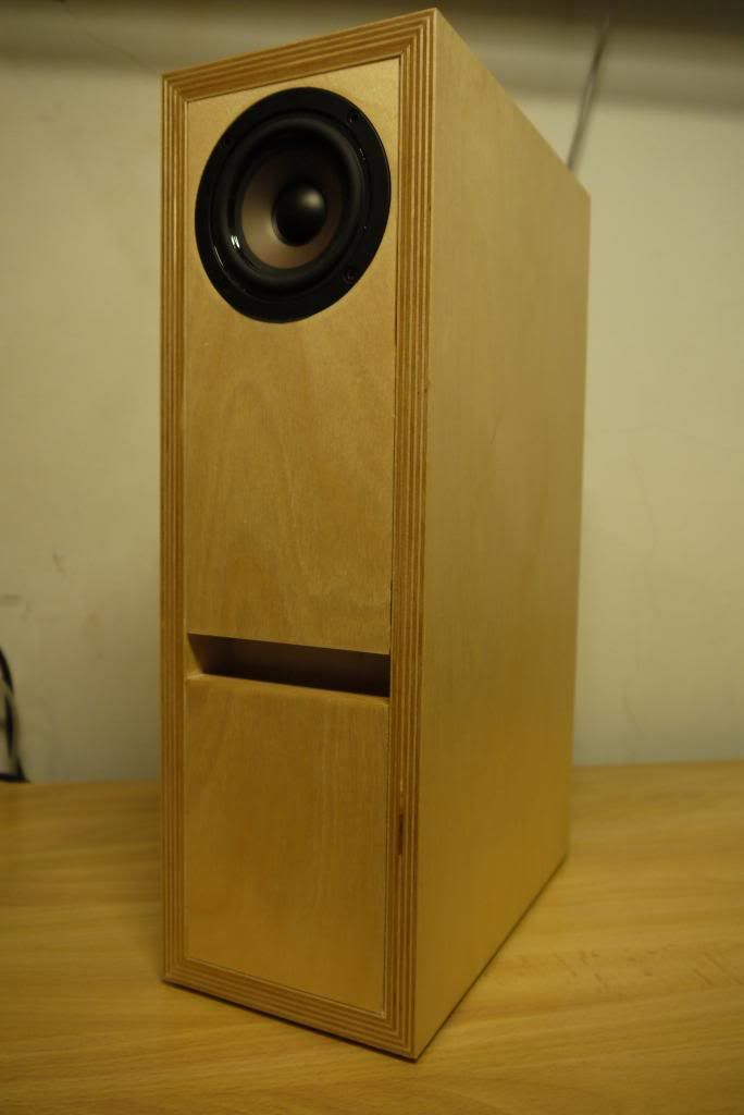
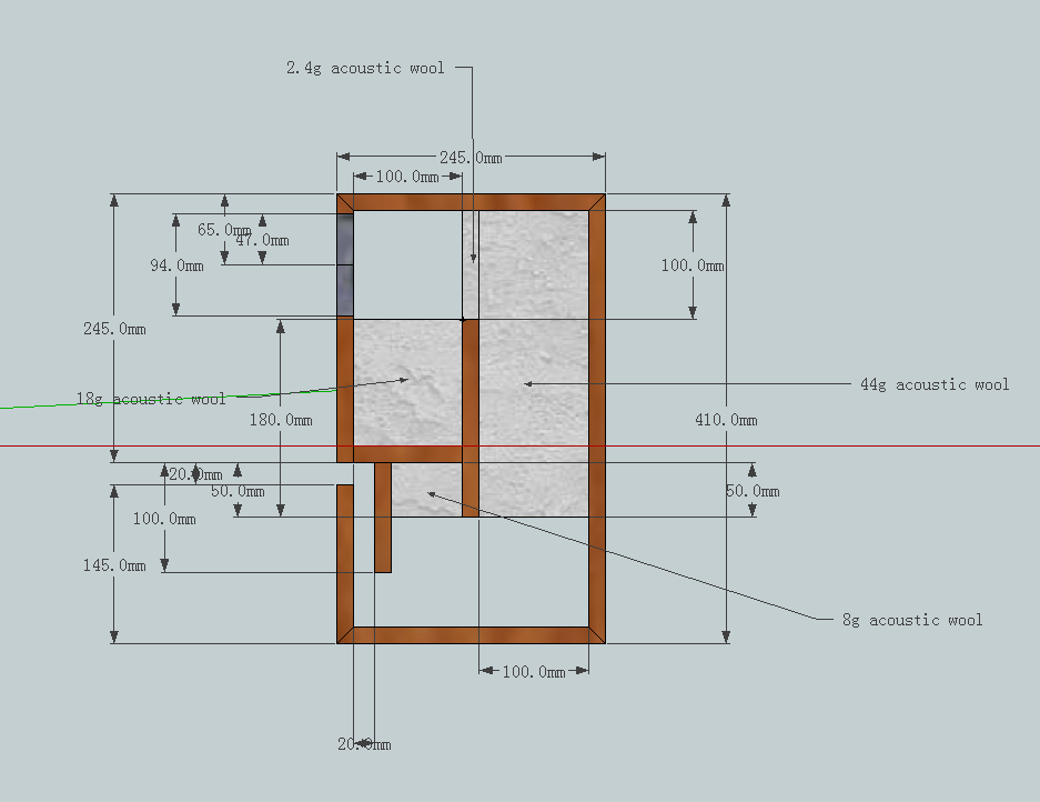
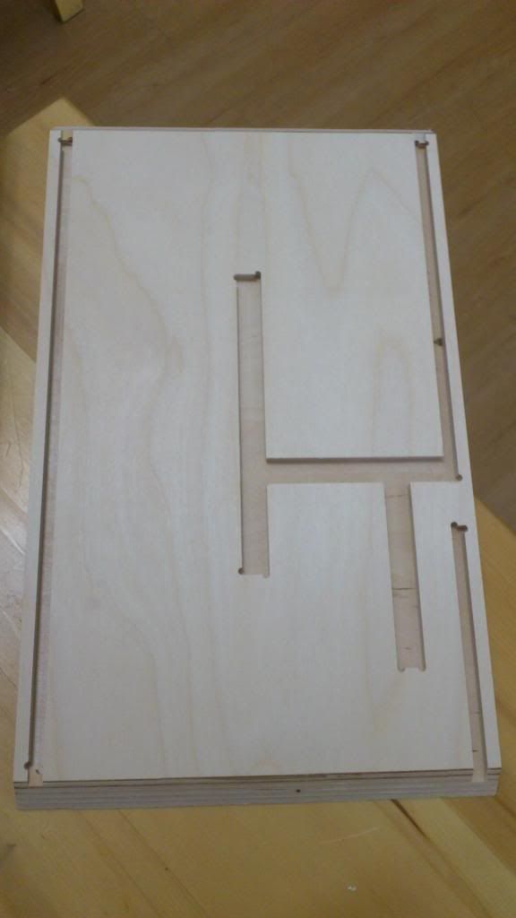
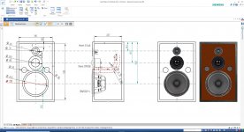
I won't replicate this exact build, but I have my eyes set on the Tang Band W4-1720 in vented a 6 litre enclosure paired with Dynavox AMT-2.

As per the official pages:
The enclosure for the Speedster is 5.5 Liters. It has a 1.375" dia port that is 4.5" long (mounted directly behind the tweeter). This tunes the box to about 55 Hz. The -3 dB point of the W4-1720 in this size box is in the mid 40 Hz range, which is quite satisfying (more on that later).
(Alas, there is very little on that later.)
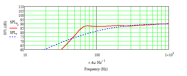
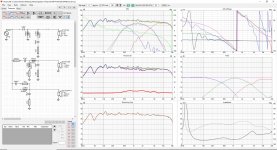
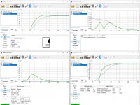
A 40ish F3 with a 4" woofer in cabinet that small? Impressive! Surely I can aim for a similar result, once I get a hang of this whole DIY thing? And so I decided to feed the T/SP, box and vent data into WINISD to verify that this could actually work. WINISD won't let me specify the port length but everything else, and in fact recommends an even longer port. This is how it looks:
2022-03-14_21-38-09.png
That's nice and smooth graph for sure, but with a steep and early dropoff. Nowhere near 45 Hz at -3dB! The Speedster's crossover doesn't seem to play a role in that (or does it? I'm only just learning how crossovers work, with XSim and SPL trace and everything, so keep in mind that I am exactly as clueless as it seems). Anyway, I've looked for other explanations. Incorrect TSP (or units) were the prime suspects. But they are all in line with the specsheet.

Except... this posting on parts express' techtalk caught my attention:
I measured 4 of these W4s about 5 yrs. ago. The T/S specs actually were quite close to factory, eXcept Vas - it was considerably smaller (less than half of TB's spec), so much so that even Paul's 5-6L Speedster box looked a tad large! ... Vas 0.07cf (some were closer to .08, but NONE close to TB's 0.2 !)
Changed the VAS in WINISD, and sure enough:
2022-03-14_21-36-43.png
Not that smooth anymore, but it looks more in line with that infamous F3. Air speed looks good... cone excursion not so much, but that also applies to the original VAS. Now, all this reeks of confirmation bias. A woofer so widely used and nobody except one dude noticed this? Don't think so. What am I missing?

Maybe I should just call it a day, move on to a different chassis and work it from there. But I'm trying really hard to understand the basics and not go by feel. Can you help me with that? 🙂

Thank you kindly,
v3

Xkitz 2-way Active Crossover Kit

I just stumbled across this crossover kit. It looks works off a single DC supply (if I have read the product manual correctly) and can be ordered with parts for different frequencies. It is listed under their 'new products for August' in their audio kits section which may explain why I had not seen it before.

Anyone have any experience with building one of these? They are only mono and I was thinking of using one for an active-crossover center speaker perhaps.

Misinterpretation of Measuremenets

It is now quite easy to make measurements of frequency response, distortion and noise using a PC and a good quality soundcard but misinterpretation of the graphs produced has led to some performance claims that sometimes defy the laws of physics especially when it comes to noise.

Here is an example from the "The Wire" thread:

https://www.diyaudio.com/forums/headphone-systems/179298-wire-ultra-performance-headphone-amplifier-pcbs.html

The second post includes an FFT plot from which the author states "the noise floor is down at -145dB" which at first sight appears to be the case as the noise seems to bump along at about -145dB. But the FFT plot is of the noise per root Hz. To get the total rms noise over the entire audio spectrum (which is what you hear and measure with a regular meter) you need to integrate these measurements over the 20KHz bandwidth. This is not complicated to do but if you assume the noise is more or less constant over the entire audio spectrum you can simplify it considerably. All you need do is multiply each measurement by the square root of the bandwidth. The square root of 20,000 is 141 so the rms noise over 20KHz is 141 times the value on the graph or 43dB higher. So the rms noise is -102dB which is still a very good result but not as incredible as the stated -145dB.

Cheers

Ian

New Project Critique Please

I am about to launch into a new 3 way project and would like to hear views/comments etc. form the forum members before I commit to the driver buy.


  • 3 Way initially active with Minidsp (Nanodigi + 4xKardas Toneboard + Rotel RMB1066) then maybe passive later
  • Box size - Re-use Akai SW125 with extra bracing and sound deadening panels (bitumen) plus 25mm MDF baffle level with box edge - external 350 x 560 x 295mm (13-7/8" x 21" x 11-5/8") - approx 40litres net volume
  • Drivers - SB WO24P-4 + Morel EM1308 + Morel ET448
  • Crossovers - doing some modelling in Boxsin 2.0, Vituixcad and Jeff Bagby's PCD I get good consistent result with the published data (obviously will measure and re-do) with very good phase tracking with all LR2 electrical at 700hz and 3600hz plus a tank/notch on the woofer at 3500hz and a notch on the tweeter at 4500. Mid out of phase. The crossover point are also fairly consistent with the couple of papers that Jeff Bagby produced on the EM1308 and ET448 which gave me some confidence I was on the right track.
  • Alignment - for the WO24P-4 40l is pretty much spot on for a sealed box and also can be used as a BR tuned to 28hz giving a very slight lift at 75hz, F3/6/10 are 52/38/28.5hz and 38/28.5/24hz respectively according to WinISD.
Any thoughts on whether there is a decent chance of success before I commit. Thanks in advance.

Attachments

  • Active Xover 1.JPG
    Active Xover 1.JPG
    431.5 KB · Views: 316
  • Passive Xover 1.JPG
    Passive Xover 1.JPG
    431.4 KB · Views: 321
  • DWG 1.JPG
    DWG 1.JPG
    229.9 KB · Views: 336
  • Winisd box 1.JPG
    Winisd box 1.JPG
    215.2 KB · Views: 328

Design to bamboozle you.

Been learning Python programming language.
A bit of steep curve to start with but managed to create an small ecommerce website.
SO next step is to get the site hosted online.
Azure is very expensive so took a look at AWS.
Eventually worked out I needed AWS SDK to send website up to AWS.
I had to store a key and a security key in AWS which was done using command prompt.
So managed to upload my website but it all i get is error 403 credentials are wrong message.
SO i uploaded a node js project and that uploads and runs fine so that suggests my credentials/logon data are fine.

I had a dig around on AWS and the website is stored in a S3 container but for some reason AWS arent unzipping the output from Visual Studio.

AWS dont support "free tier" users so that was a waste of a day or two trying to get it to work. The forums seem to get very few replies.
I complained to AWS sales that their website isnt working right and they just say I have to upgrade my service package to get help.

My view of AWS is its bloated, far too complicated and extremely slow.
Azure is much better but expensive.

Lost faith in my tube tester+

I have an early 60s Philco tube tester. It's a beautiful piece of industrial art if you ask me. The quality of the components is top notch. It looks really steam-punk too.
However.....I was fixing a friends guitar amp. Kind of a hybrid - a solid state reverb driver and effects loop implemented with op-amps, but all the rest is tube and circuit board mounted everything to my chagrin. (The Chinese have figured out how to make a tube amp inexpensive)
By the third stage the gain dropped off dramatically. In fact, on ten, the amp whispered. This was apparent using my o-scope.
This thing was giving me da bizness!
I removed all tubes and tested them - all good according to trusty Philco.
Finally I decided to measure bias voltages.
The third stage plate read 1.3 volts - ahah ---I measured the plate resistor in circuit- infinite R, it had gone open I ASSumed. I replaced the resistor and still a whisper. I measure the plate resistor it read 150k properly...what? Ok, you can't measure resistance in circuit - I should know better.
Finally in desperation I replaced the tube and voila all was good.
I took the tube (12AX7) and tested in my Philco. All measurements were good. The gain ws as good as other 12AX7s. I put the tube back in the amp - no sound. I put the tube in another amp - no sound. I put the tube int he tube tester again - measure good.
My world is rocked!
So much for my Philco.
Anyone care to comment on tube testers?
It is now industrial art only and has no other value.
I will hang it on my lab wall.

Can a 60Hz woofer enclosure tune to about 40Hz?

Hi I am working on a Bluetooth stereo system, please help me with these doubts.
1. Fs of my woofer speaker is 63Hz, so can I tune the enclosure to 40Hz or low?
If no, at what frequency should I design!
2. Two woofers can share the same enclosure volume, since they are same spec and receiving the same signal?
3. Adding a speaker cloth cover in front of the port hole will affect the bass output and tuning!!?

Woofer spec: 6inch 4ohm woofer, 40Watt RMS, Peak 80Watt, 2Nos
Fs= 63Hz, Qes= 0.5, Qms= 4.77, Qts= 0.45, Vas= 15.94ltr
Tweeter: 10Watt, 4ohm, 2Nos
Amplifier: tpa3116d2, 2*80Watt
Thank you:cheerful:

The Infinite Improbability Audio Rack

Hi All,
I had the necessity of a bigger audio rack for my setup, wich now includes a 4U/400 Dissipante from Hifi2000. Since I have almost zero carpentry skills, I needed a simple project but the result had to be a sturdy cabinet, since the power amp is very heavy and I needed at least 4 shelves...

And it had to be a quick project, as I have gear everywhere, faster than a warp engine...

Thanks to the plans sent to me by Syrius Cybernetics Corporation 😀 I had a way to proceed!!!

Hg2tg-heart-of-gold.gif Infinitedrive.jpg

Yes, It’s time for an Infinite Improbability Drive Rack! :rofl:

So, I bought some Marine Pine Plywood (or, if you prefer, Military Pangalactic Police) in form of 60X50cm boards, I used some aluminium tubes oxidized with caustic soda that I had from a previous project (something with Impulse Drive Engine :snail: ), M8 threaded rods, washers and nuts. Obviously the golden drive had to be stolen using robots… 😀

With a Point Of View Gun on hand, I started the build!

PSX_20210715_002311.jpg PSX_20210715_002331.jpg

PSX_20210715_002359.jpg PSX_20210715_002419.jpg

PSX_20210715_002445.jpg

I made some wooden discs with the internal diameter of the tubes...

PSX_20210715_002523.jpg PSX_20210715_002553.jpg

...holes in plywood for the threaded rods...

PSX_20210715_002615.jpg

...and glued 'em to the shelves
Projects by fanatics, for fanatics
Get answers and advice for everyone wanting to learn the art of audio.
Join the Community
507,755
Members
7,886,827
Messages

Filter

Forum Statistics

Threads
406,162
Messages
7,886,827
Members
507,755
Latest member
busgroove82