Bench power supplies...

I'm starting to dabble in solid state a bit (mostly a tube guy) and want an inexpensive bench power supply to help. I have a Lambda high voltage supply that was given to me for working with tubes but that won't help with ss. My first ss project is a subwoofer amp so I need something that can handle 150W output or more, ideally under (or close to) $100. I'd like it adjustable to at least 30v, but 60v would be ideal. I've been looking around and new adjustable switching supplies are everywhere and can be had for under $100. I've also found a few linear supplies that might fit the bill, but they tend to be much lower current for a given voltage and price. I'm not looking for a high-end, highly accurate supply here (though maybe I should...).

So I have a few questions. First, I know linear supplies are in general quieter (in terms of output) than switching, but how important is that for building and simple testing? And if it is important, could I add a small cap across the outputs of a switching supply (small for higher frequency noise) to help reduce that noise? I've read that many switching supplies are also not very good at fast transients so I assume I could in theory also add a large reservoir cap. Basically, will I be happier with a linear supply even given the lower current/power? Any recommendations for something that fits the bill?

Or, should I DIY a linear supply to meet these general goals? I did some research on this many years ago but gave it up as too complex. I think I could do it now. If so, can anyone suggest some designs? I could probably design a very simple supply, but am looking for something a bit more carefully designed than I could do.

OK, I'm not a highly skilled builder (though I've built quite a few amps (tube and solid state), preamps, phono-stages, speakers, etc.) and I understand that this may be a lot more complex question than I realize, but some general replies would be helpful. At least for now. Thanks so much!

DIY bass sound absorbers

Since sound absorbers like I need are not sold, I came up with the idea of building them myself.
I need damping in a relatively narrow band on bass frequencies, at about 40, 60 and 80 Hz, it makes sense to build dampers with a membrane.
I found one page what seems to give easy absorber calculations: http://mh-audio.nl/Acoustics/PResonator.html
I also found an example where the damper made based on the previous calculation seems to work https://www.musiker-board.de/threads...echnet.741282/
You can see see results on example link on the post before last on pictures with header "Zur besseren Übersicht vorher - nachher", I used Google translate to read this page.
However, there are small doubts for me.
How the calculation sheet doesn't take into account membrane stiffness at all, only mass and panel depth?
How can such a small absorber have such a large effect on 30 Hz as seen the sample page images?
Did I miss something here?
Have someone other bass sound absorbers built ideas what can be DIY?

Kicker ZX700.5 low volume from Amp 1

Hello I have a Kicker zx700.5 that I got at a yard sale. Amp2 seems to work fine but amp1 outputs have very low volume in comparison like it's muted. Sub works fine. I can hear something buzzing on the amp but I haven't located it yet. Any suggestions? Thank you

Here are some measurements I took from the preamp board to speaker ground:

Fr in -18.3 mv
Fl in 9.6 mv
Rr in -19.3 mv
Rl in 10.0 mv
-15v -14.14 v
+15v 13.95 v
Rem 11.51 v
Gnd a -4.5 mv
+ Batt 11.63 v
Gnd p -4.5 mv
Rem- bas 12.3v
Sub in 15.3 mv
Sub pre -4.4 mv

Attachments

  • PXL_20250211_170556286.jpg
    PXL_20250211_170556286.jpg
    644.9 KB · Views: 66
  • PXL_20250211_170618219.jpg
    PXL_20250211_170618219.jpg
    664.1 KB · Views: 57
  • PXL_20250211_170626019.jpg
    PXL_20250211_170626019.jpg
    743 KB · Views: 56
  • PXL_20250211_170636476.jpg
    PXL_20250211_170636476.jpg
    618.7 KB · Views: 52
  • PXL_20250211_170802270.jpg
    PXL_20250211_170802270.jpg
    690.3 KB · Views: 52

Steinway Lyngdorf Model B

I’m trying to confirm how the 6 woofers (3 forward facing and 3 rear facing in adjacent vertical arrays) are configured in this speaker, including the baffle arrangement. It appears from some photos and videos that I’ve seen that the front and rear baffles only extend half way across the width of the speaker so as to allow the sound wave emerging from the rear of each set of 3 speakers to travel to the front or rear of the speaker, as the case may be. To put it another way, both sets of 3 woofers are operating as true dipoles and are projecting sound into the room in both directions.

Is this correct?

Also, presumably the rear facing set of 3 are electronically out for phase with the front facing 3 so that all 6 push in the same direction at the same time - ?

Troubleshooting an NAD T751 With Low Output on One Channel

I am more of a tube radio guy, but I am trying to figure out a low output channel on a friend's solid state amplifier. I have tracked down a number of symptoms and I am hoping that someone might be able to help me with a diagnosis. I would be very appreciative of any ideas you might provide. The schematic for the Front Amplifier board is shown, but I am not sure if it will be legible.

  • There is very low output on the front left channel, regardless of the input source. (Yes, speakers have been switched - problem remains on the left side.)
  • When the receiver is turned on, the left channel is too quiet to hear, but slowly increases in volume until it is about 25% of the right channel. The sound is intermittent until the volume is increased, when it becomes steady, though quiet.
  • A number of component in the left channel are warmer than those on the right. For example, R521 (right channel) is 44 C, while its corresponding resistor on the left (R522) is 51 C. R523 is 31 C and R524 is 44 C. More interesting is that C525 (470 uF / 63 V) is 29 C and C526 about 36 C.
  • Measuring the Voltage at the idle current measurement points, I found the right channel measurements at P501 to be 4.9 mV DC / 0.1 V AC, whereas the corresponding left channel measurements at P502 were 21.6 mV DC and 0.02 V AC. Cap leakage?
  • The problem is unlikely to be in 10,000 uF filter caps (C561 and C562) as they feed both right and left channels.
It seems to me that the problem is likely to be a leaking electrolytic cap on the left channel rather than a bad transistor and that I should remove the board and replace the electrolytic caps. Does that make sense to the more experienced techs?

Thanks as always for any help/suggestions/insights/next steps you can provide.

Andrew

1730310269121.png

Electrocompaniet Ampliwire 100

I have an opportunity to pick up an Ampliwire 100 with a shorting problem. Doing a quick take I was able to determine that the problem is from the right channel after the power supply. By any chance does anyone know if this particular model amp is plagued with problems? A few folks seem to think so - I just do not have much history on its reliability.

Thank you for the help.

what do you really think of Wilson Audio?

yes we all know that anyone in this forum can make much better speakers than wilson audio does, but still, what is it that wilson audio speakers do so well that so many audiophiles love? and audiophiles and critics have loved wilson audio speakers for a long time now!

it seems absurd that wilson audio would be a bad speaker manufacturer but still have so many fans

https://www.stereophile.com/content/icing-munich-cake-mcgrath-fon-nagra-wilson-impex

Restoration and Modification of Pioneer PL-71 turntable

This thread will be for the documentation of the restoration and (probable) modification to a Pioneer PL-71 turntable.

Why the PL-71? A couple of reasons:

1) It's a good example of pre-PLL direct drive. The motor is very quiet and it's bearing structure are good.

2) It has a wonderful tonearm made by Acos.

3) The turntable is generally considered to be a good example of "better than the sum of it's (quite nice) parts".

4) It's the turntable I grew up with, and 5) I didn't actually expect to win the auction.

Fantastic reference thread here - A new toy - PL-71.....

IMG_2428.jpg

Here it is in the condition I recieved it. The wood is a bit dry, there is a general light yellowing of all the metal parts indicative of it living in a smoker's household at some point, but other than that, it's in very nice shape.

IMG_2431.jpg

And here it is after a thorough cleaning. The yellowish tint is off the metal, the wood has a coat of Danish oil, and generally it look much, much better.

I didn't take any photos as I was cleaning it, just imagine a bunch of paper towels, cotton swabs, alcohol, wood oil and the like all strewn about. It took approximately 1.5-2hr of scrubbing, dabbing, cleaning, wiping, brushing and elbow grease.

I still need to treat the mat, it's clean, but the rubber needs something to restore a bit of moisture to it.

IMG_2433.jpg


IMG_2435.jpg

The dustcover is is great shape for it's age. I'm very pleased.

IMG_2436-1.jpg

The bottom cover is very 1973. But the metal chassis bottom is a neat piece, making a metal interface for the sprung feet into the wood chassis that makes up the rest of the table.

IMG_2437.jpg

Here's the up-skirt shot.

IMG_2448.jpg


IMG_2441.jpg

A few things worth mentioning, the tonearm is rigidly coupled into the chassis, and with the tagboard and jacks easily removed, would be a good candidate for a continuous rewire or conversion to DIN if that's you kind of thing.


IMG_2439.jpg

This board is mainly for AC distribution.

IMG_2438.jpg

DC rectifier and 'regulator' (Really just a zener-referenced cap multiplier.)

IMG_24401.jpg

The power/speed selector switches and speed trim pots.

IMG_2442.jpg

These little screws holding the motor cover were a royal pain to remove.

The power transformer is mounted on rubber feet. Remarkably quiet. Of course it would benefit from being in it's own external case, and I may try that. It also has a universal primary and voltage selection with one of those neat plug thingys.

The motor is rigidly coupled to the chassis and the control board is under the black cover.

IMG_2445.jpg

Cover removed showing the motor control PCB. The 38yr-old capacitors need to be replaced. (Yes, one is already replaced in this photo...)

IMG_2446.jpg

Not too bad of a job. There are a number of wires that got the the motor windings on the other side of the PCB that seemed to be in the way, but other than that, it's straightforward. No values changed

IMG_2443.jpg

The regulator board also got a set of fresh capacitors. The filter caps are a bit bigger than stock, but the can size is still the same. 😎

IMG_2447.jpg

Dead soldiers.

IMG_2450.jpg

I replaced some screws that hold the strobe to the chassis, over the years 3 of the 4 screws had fallen out. I had to scrounge for hardware that fit, but now it's solid.


IMG_2451.jpg

Lastly I added some secret lubricant to the bearing, I got it from a kindly old Dutchman who horse-swapped it from a Polar Bear named SY. I have little idea what's actually in it, other than it was made for low-heat, high-pressure interfaces, specifically TT bearings.


In my opinion, all I did was to get the 38-yr old table back in a condition similar to when it left the factory. So far it's just a tune-up, no hot-rodding, no mods.

Yet.

🙂


Edit -

There has been a number of reports of people trying different mats, and always returning to the stock one. I have a theory why -

(click link for video) https://www.youtube.com/watch?v=zxbj0a-AzuI
  • Like
Reactions: Bonsai

Electrocompaniet Ampliwire 100 (AW 100 AW100) different Versions

From this power amplifier I have service manual together with two different schematics (year of production approx, between 1979 and 1983). Additional I have newer version for repair service. The schematic, that I have create (Reverse Engineering), is different again compare to the already present orig. versions. Even the cabinet version is different in opposite to the older version.
How many different versions of the AW 100 are exist at whole ?
Thank you for your advices.
  • Like
Reactions: Nessman

DIY 4 Phase Sinewave Generator for Turntable Motor Drive

This is a shared DIY project for non-commercial use.

The SG4 generates 4 low distortion, high accuracy sinewaves suitable for driving conventional audio power amps to create a multi-phase drive for turntable motors. The generator outputs a reference sinewave at 60/81Hz or 50/67.5Hz on the 0° pin. The 90° pin outputs an exact replica of the reference sinewave, but shifted +90° (Cosine) for driving 2 phase AC synchronous motors. The 120° & 240° pins output an exact replica of the reference signal, but shifted +120° and +240° respectively for driving a 3 phase motor. The SG4 is a sinewave generator only. You will need to add the necessary 
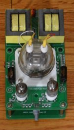
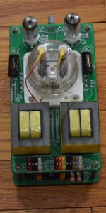
audio Power Amps and step-up transformers (if needed) to create the final signal to drive the motor. Low cost linear and class D amps are readily available on e-Bay and other on-line sources. 
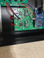
Working with High Voltage can be dangerous. Do not attempt this part of the project if you are not trained in handling power electronics: Seek competent technical help if needed.

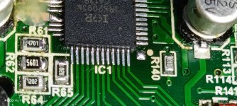
The PCB uses all thru-hole components for easy assembly, but some soldering skills are still required. The µP is a PLCC package but there is a socket for it on the board.

The project consists of a bare PCB, a parts "kit" available as a shared cart from Mouser electronics, a µP with the operating system pre-programmed into it and the on-line documentation you see here.

The PCB is available from OshPark PCB fabricators at the following link: https://oshpark.com/shared_projects/E5zXjeJd
The PCB is created in multiples of 3 for a cost of ~$45 or $15/board.

24-Feb-2022 The parts kit at Mouser has been updated to include the MCP101 reset controller that replaces the DS1833 part. The pin out of the MCP101 is the mirror image of the DS1833 so the PCB has also been updated to Rev C to reflect this. If you are using a Rev A or Rev B PCB, you must insert the MCP101 part backwards; the Rev C PCB does not require any change.

The parts kit can be ordered from Mouser Electronics: http://www.mouser.com/tools/projectcartsharing.aspx
Enter the Access ID code: 7A6A645FFA. The parts kit to build 1 PCB costs $32.34.

The pre-programmed µP is available in the US from DIYAudio member Seth Hensel via email: sethhensel (at) icloud.com. Cost will be ~$12 plus $8 handling plus shipping.

The pre-programmed µP is available worldwide from DIYAudio member ralphfcooke via PM. Cost will be ~£10 plus shipping.

The following documentation is available below to aid in construction of the project:
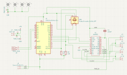
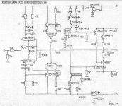
SG4 Schematic.pdf
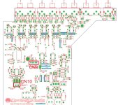
SG4 Parts Locator.pdf
SG4 Assembly Instructions.pdf
SG4 BOM.pdf (Generic bill of materials with part references)
SG4 CART.pdf (Mouser cart with mfr's part numbers and costs)
SG4.zip (Gerber X274 files if you want to use your own PCB fabricator)
SG4.png (X-Ray view of the PCB w/traces, pads and silk screen)

The SG4 uses a 20 bit DDS core implemented in software to generate the reference sinewave. Frequency resolution is 0.01Hz. Frequency range is 40.00-70.00 Hz for 33 RPM and 60.00-90.00 Hz for 45 RPM. There is an on-line video showing the frequency operation Here and a video for phase adjustment Here.

There are four 8 bit phase accumulators to generate the four phases. The reference signal is fixed, but the other 3 are adjustable in 1.5° steps ±15° maximum. D to A conversion for the 4 signals is done with 8 bit PWM at 18kHz. There are 4 LPFs on the board to convert the PWM signal to analog. The outputs are DC coupled, 5VPP and centered at 2.5VDC. Distortion is ~0.5% (-46dB) and frequency stability is 30 PPM.

Update: The firmware has been updated to version 1.02. A 7 bit linear taper attenuator has been added to ramp the voltage from 0 to 5VPP at start up when exiting standby mode. This should prevent the amplifiers from shutting down when first started as they will have time (~650mS) to overcome the core magnetization of the transformers. I also added a reduced output voltage mode, where the output voltage will automatically be reduced to a user programmed level after 5 seconds. The level is adjustable from 128 (maximum) to 64 (half voltage) in ~40mV steps which equates to ~1V steps at the transformer outputs.

19-Nov-16: I returned the phase adjustment to 1.5°/step. One of the peculiarities of using a 16 bit phase accumulator with an 8 bit DAC (PWM in this case), is the limited precision math can create different points where a carry occurs (and thus an additional phase step). For most frequencies, this isn't noticeable as the difference in phase shifts is usually in the mSec range. In certain cases, the math works out where it becomes quite noticeable and in the audio range where it could affect performance. Using a 16 bit phase accumulator in the SG4, a nasty phase spur will occur on either side of 81.92Hz, which is fairly close to the frequency needed for 45 RPM. The new firmware hasn't hit the field as of yet, so there will be no need to do another exchange. V1.02 will ship with the attenuator capability, but will retain the 1.5° phase adjustment of the original.

Users who upgrade to the new firmware should perform a Factory Default Reset after installing the new firmware.


28-Dec-2016: Just added the PCB files to OshPark for a Rotary Encoder to SG4 interface PCB. The circuit converts the 2 quadrature signals from the encoder to a single pulse train on the UP pin when turned CW and a single pulse train on the DN pin when turned CCW. The momentary push button switch of the encoder is connected to the STBY button of the SG4. This allows all of the normal operating functions to be performed by one rotary control.

The 1 inch square board uses all surface mount components in order to keep the size down. The IC is a CD4013 in SO14 package. C1 and C2 are both 0.47uFd Tantalum caps 10V rating in a 1206 size package. R1, R2 and R3 are not necessary if you use the Arduino Rotary Encoder which has the pull up resistors already on its PCB. If you use another encoder without pull ups, add the 3 resistors (all 10K 0805 size). Vcc is connected to the 5VDC output of the regulator on the SG4.

You can order the PCB here ($5 for three):

[url]https://www.oshpark.com/shared_projects/AbsVI39H[/URL]

The Encoder PCB can also be ordered with thru-hole component layout instead of SMT:

[url]https://www.oshpark.com/shared_projects/W6QWOCOF[/URL]

1-May-2017: Version 1.03 of the SG4 firmware reduces the lower frequency limit to 1.00 Hz for both 33 and 45 RPM. The reduced lower limit was needed for 3 phase BLDC motors, some of which require 20Hz for 600 RPM. If you are not using a 3 phase BLDC motor, there is no need to update the firmware.

16-May-2017: A DIY 3 phase amplifier project is now available to drive a BLWR172S-24-2000 or BLWS231S-24-2000 BLDC motor from Anaheim Automation.
It is not a universal controller and will only work with these two motors: 3 phase class D DIY BLDC motor drive amp


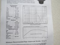
A suitable audio power amp and step up transformers are available here: 60-wpc-amplifier-diy-turntable-motor-drive


13-Dec-2021 The PCB has been updated to Rev B and the firmware has been updated to v1.04. These changes add the ability to use a 2 x 16 character LCD display that has an I²C interface PCB with a PCF-8574A interface chip. Version 1.04 firmware is backward compatible with the previous PCBs so an LCD display can be added to a previous build. The details of all the changes can be seen here: SG-4 Version 1.04 Update

It is important the LCD interface chip is a PCF-8574A and not a PCF-8574; the two chips work nearly identically, but have different address schemes. The new SG4 firmware will only work with the PCF-8574A addressing.

Attachments

Trying to Restore Mitsubishi DA-R35, Zener Diode Question

I have a couple of these nice 1980 receivers. Not top shelf material, but quite good. They use ICs for L/R voltage amplifiers (STK 3076/3106) and individual ICs for L/R power amps (STK-1080 II), three ICs in total 😕. Both have blown voltage amplifier ICs, but I am finding other surrounding problems such as 4558 op amp blown and zener diode MZ324.

Does anyone have an idea on this MZ324 zener diode and its specs? I need to find a current match.

I am attaching the part in the schematic with the MZ324 zeners highlighted in red. Maybe someone can have an educated guess as to one that will work in both positions.

Thanks in advance.

Attachments

  • ZENERS.png
    ZENERS.png
    211 KB · Views: 309

New project - PSU confusion

Hi,

Got a visit from my neighbor yesterday while enjoining my ACA + Korg, apparently it was to loud. Enter Honey Badger.

Still going through all the docs here and creating BOMs so I can pull the trigger on the parts, and of course have a ton of questions.
As the amp section is pretty much as is regarding the PCBs and parts (except some transistors and caps, still figuring that out...), I'm not sure about the PSU. I see there are two on the store: Nelson's bipolar PSU and Universal PSU.

The idea is to go with the 2x150W stereo config, and update to mono-blocks later if needed....

1. Which PSU to go with?
2. One or two PSU boards?
3. What spec toroidal to match with the PSU board(s)?

As always, much appreciated for all the help!

Cheers!

Cambridge 640A V2 with DAC module Musical Fidelity V-Dac V1

Hello

I modified my amplifier Cambridge 640a V2 & I install inside the amplifier a dac module from Musical Fidelity V-Dac V1 (Usb-Optical-Coaxial Inputs)
I need space for this Dac and I remove the A-Bus PCB Board, and I disconnect on Input PCB Board, connectors CN9 and CN10 (From A-Bus PCB Board)

The amplifier working fine, but like you, the remote control is not working !!!!!!

I am not a specialist of electronic systems
Do you have a solution to solve may problem, because I saw in the past you have same trouble
Let me know
Regards
Rabia

Attachments

  • 640A V2 - A-BUS PCB Board.jpg
    640A V2 - A-BUS PCB Board.jpg
    228.5 KB · Views: 23
  • 640A V2 - INPUT PCB Board.jpg
    640A V2 - INPUT PCB Board.jpg
    138.3 KB · Views: 23

Board 3 Way DSP Amp

I will post the availability and price of the 3 Way DSP Amp boards here.

TOP Plastina+ESP32.jpg


Read more about the boards here.
https://www.diyaudio.com/community/threads/3-way-dsp-amp.415065/#post-7734899


The price of one 3 Way DSP Amp board is $95.

The price of one I/O board is $15.

Delivery to Europe and America is at my expense. Delivery to islands or other distant places is negotiated separately.

Order more than one 3 Way DSP Amp board and get $5 off.

Payment via Payoneer.


We currently have four 3 Way DSP Amp boards and four I/O boards with ESP32 available.

For Sale Miro AD1862 DAC

I am selling my fully built AD1862 DAC based on Miro's design. Used all good components like DAC chips from Rochester, Opamps - OPA1655DR and OPA1611AID and I love both of them so will include both in the sale. JLSounds i2s dac board sitting on top of the dac which is USB powered and I have not modified it to power externally. I like this way as I use a galvanically isolated USB from my streamer. RCORE to handle the power supply using Miro mini psu works perfectly. IEC socket have used a EMI/RFI filter built in for filtration. So its a clean and distortion free DAC playback I can hear.

The dac is being used in my second system which replaced my Soekris R2R 🙂. I am moving homes where unfortunately I do not have enough space for 2nd setup, so most of my second system is being disposed off. Slight scratch marks on the bottom plate because of usage otherwise rest of the chassis is pristine without any marks.

Asking price $576 including CONUS shipping and I will include a IEC power and a USB cable.

More information of this DAC here :
https://electrodac.blogspot.com/p/dac-ad1862-almost-tht-i2s-input-nos-r.html
https://www.diyaudio.com/community/...s-input-nos-r-2r.354078/page-209#post-7049224

Attachments

  • IMG_0001.jpg
    IMG_0001.jpg
    556.3 KB · Views: 355
  • IMG_0002.jpg
    IMG_0002.jpg
    468.1 KB · Views: 367
  • IMG_0003.jpg
    IMG_0003.jpg
    420.7 KB · Views: 317
  • IMG_0004.jpg
    IMG_0004.jpg
    438.3 KB · Views: 313
  • IMG_0005.jpg
    IMG_0005.jpg
    649.1 KB · Views: 282
  • IMG_0006.jpg
    IMG_0006.jpg
    452.2 KB · Views: 332

KENWOOD KT-5020L INTERMITTENT FAULT.

Hi All. Sadly, my KT-5020 tuner has developed an intermittent fault. It works perfectly but every so often, it has started to produce no audio at all. This presumably is because something in the "front-end" is failing as the display shows zero signal strength when the sound disappears. If I leave it switched on, it will suddenly work normally again after a few seconds of making a rustling sound in the output, then normal clear audio. Sometimes switching off after the fault appears occasionally gets it working again normally when switching back on. Could someone help me here please?. I could fix it but have no hands on with tuner fault finding at all. I attach the circuit diagram. Many thanks for reading. The file is safe to open.

Attachments

Building a Crossover for 450w RMS Woofers

Hey Diy Audio Crew!
This first post here, don't be to hard on me:')

in the planning stage of building a pa loudspeaker, including six 6" woofers, rated at 75w rms each. (Dayton Audio PA165-8 6)
wondering what sort of cross-over components won't blow at 450 wats. going to cross it over probably at 2500 hz or earlier.
also thinking of using the Pyramid TW44 Heavy Duty Titanium Super Tweeter with the included crossover. (posting that here in case people see a fault in my parts choice.)
just having struggles with finding cross-over components that won't blow. 🙂

all parts on parts express if you want to look it up.

Revox A77 Re-Cap Job

Hi All

I assume someone here has done this already. I already sourced most of the trimmers for this job. I have already tackled the power supply too.

I am looking to re-cap these boards:

Switch Board
Input Amplifier
Record Amplifier (2x)
Oscillator
Record Relay
Playback and Drive Amplifier (2x)

Gee, this cap list is looking evil right now. Can anyone share their experience (and maybe their list) for this?


Some of the electrolytic values are hard to find too. Some of the 3,3uF values could probably be replaced by Film (MKP) once I look at the schematics. I am tempted to try Film caps in what looks like coupling positions. Any reason not to do this?

My machine is a high speed IEC one. Sounds really good. Fixing the meters was a challenge, but they are once again good.

FaitalPro XL3000 series

At ISE 2025, FaitalPro released its new beast 21XL3000.

21XL.jpg


The 6,5" CCAW coil 3000W/6000W behemoth.
Normalyzed motor force of ~313 puts it in the high end class with all these new B&Cs, 18Sounds, RCFs and such.
Looking forward to reviews and use cases.

Now, birds on the trees are chirping that we might:
A) See 4Ohm version, because this will be really difficult to feed with mortal-grade amps.
B) See 18" version. That would be way too awesome. I praised FaitalPro crew to them myself and asked for tad longer voice coil (to add my voice to that idea if it already exists, no way they are going to listen just to ME 🙂 ).

If that is the case, I am considering to not follow up on my oncoming 18" purchases in the name of this.
The price seems to be somewhat higher, but still realistically competitive with quite some competition being more expensive already.

Anyone also interested and waiting to put it into some sick design?

Preliminary datasheet here:
https://faitalpro.com/highlights/2025/21XL3000/files/21XL3000 - Preliminary Datasheet.pdf

Should be available towards the summer.
  • Thank You
Reactions: GM

is Beyma TPL 150 sonically identical to TPL 200 ?

is it just two different lengths of same pleat or is the pleat different ?

because the 200 is only 33% longer yet claims 50% higher power handling so i wonder if it may also be wider and / or deeper in the pleat.

they also seem to have slightly different frequency response in the specs, but that may be due to different measurement conditions etc.

and yet the higher power handling of TPL200 is consistent with it having slightly more rolled off top half an octave if that power handling is achieved by having deeper pleat. deeper pleat would mean more conductor surface area and perhaps more power handling as a result.

in other words you would expect a 4" compression driver to have slightly more rolled off top end than a 3" so maybe Beyma felt you would also expect the bigger AMT to be a bit more rolled off and made it not just longer but also ... different ?

i understand even with the same pleat they would sound different due to different radiation patterns but if you were to array them those differences would mostly cancel out ...

so is it the same pleat or not ?

Professional hobbyist

Hello!
I have been building and designing loudspeakers from 2019.
Master's degree in Acoustics and Audio Technology.

I'm an entrepreneur, alltough my business is not (currently) in audio. (It's in building acoustics and noise)
I have my own dedicated and acoustically treated "Studio" where I listen to music while working 🙂

I have been reading this forum for a while, but finally have decided to start contributing with my own projects.

-Jesse
  • Like
Reactions: tmuikku

Tandberg 3000x Transformer diagnosis

Hi all
Just acquired a tandberg 3000x reel to reel player that I knew needed work but didn't check it Powers on, which it doesn't. I've checked fuses and cable into transformer for continuity, still need to check the switch but want to check the transistor as well before getting to capacitors and pcb work. My knowledge of such things is non existent but can someone tell me if this looks right before I give it a good probing?
Thanks all
1000037367.jpg

Back to my System - new to this forum

Hi,
Let me introduce myself.

I'm Revoicer (really John). I'm from Buckinghamshire (Bucks) in England/UK.

I have just gotten round to unearthing my old HiFi set-up. [Stored for approx 30 years.] And am looking to integrate bits with my more modern HiFi components.

I have joined this group to get some advice.
I am looking forward to receiving your pearls of wisdom to my mind taxing (or bored you senseless) questions.

Lateral MOSFET - Capacitor Betwen D and GND

Hi, i im layouting new pcb for lateral mosfet and found this schematic of OPS.

20211206081535_Figure3-DH-220C-MOSFET-PowerAmp-P1.jpg


My question is about decoupling caps on DRAIN of mosfets. On some schematic i see 220nF between DRAIN and GND, and on some 470nF or 100nF value.
Does this mean that i need to add to each lateral mosfet DRAIN pad as close as possible 470nF?

What is recommended value for DRAIN capacitor for each mosfet (i will be using 2 pairs)?

I will be using EXICON lateral mosfets 2pairs in TO264 case.

And i read that MKT 2,2uF at DRAIN improves THD below 10kHz.

And some members suggests adding 1000uF/63V electrolytic cap to DRAIN and GND and solder on legs of this electrolytic cap 100nF MKP1837 capacitor.

I im not sure if this large capacitor will not give trouble to drain of mosfets when mosfet turns on/off as this large capacitor charges/discharges.This idea have description that it improves large currents/demands from fast slewrate audio amplifier and it is close to DRAIN to give accumulated energ to DRAIN for fast slewrate amplifier.

So what is recommended way?

JVC Victor TT-81 Schematic Diagram & PCB

JVC Victor TT-81 Schematic Diagram & P.C.B.

Schemes and boards in two versions for TAS-19A and TAS-19B boards
I redrew it myself from a poor quality scheme, maybe there are errors somewhere,
so let me know and I will redo it.
I put in a lot of work and patience, so I ask for help in checking and making comments.
Thanks in advance!
Victor TT-81 TAS-19A PCB
https://cloud.mail.ru/public/6VXX/eWdCgKCVR
Victor TT-81 TAS-19A Schematic Diagram
https://cloud.mail.ru/public/Tga7/ithR4GWWt
Victor TT-81 TAS-19B PCB
https://cloud.mail.ru/public/CWJ9/h7dtw1CV7
Victor TT-81 TAS-19B Schematic Diagram
https://cloud.mail.ru/public/PQFR/CpwRdUR34

Attachments

Pac AP4 GM61 tuning

I recently put in my sound system in my new truck with Bose, I am using the AP4 GM61, I just pulled everything from my old truck and put in new one and everything seems fine except the bass, it's non existent until I have the bass knob turned 3/4 way up and by then it sounds muddled or too much especially at medium to lower volumes. The module was installed by a stereo shop in the previous truck and I do not know what all configuring they did which might of been none cause the chime volume still about pierced my eardrums. I did set the " minimum volume " and wonder if that messed it up. The chime volume is perfect now after I set it. I am thinking or setting back to factory settings but don't know how good it would sound like that or if too difficult to try and tune with a PC. Is there a certain position to have the knob while tuning the system? Thanks in advance.

Ewidance warmup

Hi all,

Long time occasional reader, but not a big contributor since English is not my native language (French, sorry🙂 ), I’m a musician, maker and audio DIY mainly on musical instruments / devices. I'm occasionally maintaining amps, effects & other devices. I love vintage guitar tube amps and recently built a tube tester ( excellent uTracer 3+ from Ronald Dekker) to help to match and qualify tubes. I also founded and directed the Montpellier FabLab (https://labsud.org) for 6 years. Recently retired from a technical director position, got now time for my passions around music: building/repairing amps and effects, lutherie for building guitar and bass (and tuning them), rehearsal and live performances with those equipment.... But my main goal is continuing to learn & share, as technician, musician and human...

https://civade.com : DIY Blog

Have a nice day!
  • Like
Reactions: krivium

PSB Stratus gold X-over help

Hello all. I need to rebuild the x-over on my beloved Golds after I fried the x-over board, I mean burnt by an overheated resistor to the point I can't follow the board traces to get the schematics! I have called PSB and they would only give me the values of the resistors, but no schematics. Can anyone steer me in the right direction??? I will rebuild them one way or another and will post the outcome.

could this work ? ( planar dipole / CD horn coax )

let's say HYPOTHETICALLY you took the large format B&C ME464 horn:

https://www.bcspeakers.com/en/products/horn/1.4/0/ME464

1.4" BMS midrange

https://www.bmsspeakers.com/index.php-62.html?id=bms_4594nd-mid

and Radian LM8K mid-tweeter configured as dipole

https://radianaudio.com/collections/ribbon/products/lm8k-wide-band-planar-ribbon-transducer

put the planar coaxially inside the horn and crossed them over at 1.5 khz ...

the black line in the chart below is for DIPOLE operation of LM8K WITHOUT BAFFLE

1742266611829.png


so as you see you don't lose any output by going dipole - if anything you get BETTER frequency response from the dipole ( above 1.5 khz )

there is a fairly obvious SLOT shape in the middle of the ME464 horn where the LM8K would fit almost perfectly ... of course i am not talking about blocking the output of the compression driver - there would perhaps be about 3 inches of space left on all sides of the LM8K for the sound from BMS mid can go around it ... but also some of the sound would go THROUGH it as well ...

then to control the back wave from the LM8K you would put some acoustical damping material ( like wool ) right behind it as well as line the sides of the horn with a thin layer of foam or felt ...

the logic being that below 1.5 khz a horn loaded BMS mid is about 110db / watt

1742269398790.png


versus a measly 90 db for the LM8K ... on other hand the BMS will roll off above about 3 khz but the LM8K actually has rising response all the way up to 10 khz ...

so you can create a sort of a co-axial driver, not unlike this radian:

1742267686196.png


https://radianaudio.com/collections/ribbon/products/6crn38lt6-line-array-driver

only instead of a cone there would be a midrange horn and the planar would be a dipole instead of having a very shallow chamber ( like what i assume Radian is using ).

i think dipole could be beneficial here because by allowing some of the BMS output to go THROUGH the dipole it would reduce the diffraction around it ...

also even though a dipole has a rear wave it has no side radiation so as long as the rear wave could be tamed maybe reflections inside the horn wouldn't be so bad.

for example you could even stuff the horn with wool so that the low frequencies can come out of the horn but the HF back wave from the planar is absorbed instead of being reflected ...

again, for the time being i am not suggesting this would make a practical speaker but rather this is a thought exercise - the question is can it be done and would it work ?

and yes i am aware BMS is famous for their COAXIALS so you could just get one of their 1.4" coaxials on the same horn but IMHO those are also not without compromise. it is not theoretically possible to perfectly combine the output of the two BMS diaphragms. the way they combine is merely GOOD ENOUGH not perfect.

the question then is can my proposed planar / horn coax combine the two outputs WELL ENOUGH too ?

the problem with BMS and B&C coax design is that it is immutable - whereas my concept can be CUSTOMIZED for different applications ...

you may not see the value in crossing over a midrange compression horn to planar and that's understandable in which case just imagine that instead of a horn it's a woofer. and you are placing a dipole planar in front of the woofer. has anybody tried that ?

obviously Radian has done it, but not with a dipole. but i think one benefit of dipole for example is that the diaphragm conductors would be cooled from both sides rather than sealed off with a chamber from behind thus increasing output capacity ...

another benefit is that bass from the woofer won't push the dipole diaphragm into the chamber but put similar pressure on it from both sides the force thus mostly canceling out so that the diaphragm isn't as heavily modulated by the bass ( hopefully )

i already mentioned that diffraction would be reduced ...

what do you think ?

Simple amp to build

Ok, So I am looking around for a simple amp project as a fun build.
And I came across this page https://sound-au.com/project12.htm
And it got me thinking.
The last version on that page could be nice I think. Easy to stabilize and enough loop gain for decent THD specs.
Why is this simple input arrangement not used more often?
I always see the LTP in VFB amps or the basics of a diamond buffer as used on CFB amps.
But why not a single transistor?
The only downside is that it can't be DC coupled.
Using more modern output transistors could make this amp more then fast enough also.

Just some thinking.

Any ideas to improve it further are welcome.
Also any other simple amp projects are welcome.

How to find a replacement/equivalent rectifier diode?

I have a rectifier diode (I think thats what its called?) That I want to replace because it has broken legs, but I cant find the exact model, and am wondering what do I need to know to find a replacement/equivalent?

The diode is a FMU34S, Ill add a photo of it as well.

The diode tests good, at least from what I can tell, but I would like to replace it if possible.

I would like to replace its twin also, a FMU34R, if possible.

Can someone please let me know what I need to know to find a suitable replacement?

Any help is appreciated!


IMG_1336.jpeg

Slatted wood grille speakers - Retrofitting - How to select new full-range drivers?

Hello everyone, I'm starting my first DIY audio project and I have a few questions about the best approach.

I recently picked up two wooden speakers with a slatted grill from a thrift store ("kringloopwinkel") in Amsterdam. I reckon the speakers are from the 1960-1970s and were a DIY build - perhaps the housing was sold as a kit (I believe that was common at the time).

Now this pair of speakers contain two different drivers, one seemingly made by Philips and the other one by Isophon.
I'm thinking about replacing these with modern, full-range drivers that can work with the enclosure. Currently, using two different drivers won't give the best output. But I'm not so sure how to find a possible match for the housing.
My initial idea is to replace the drivers, and install a Raspberry Pi with HiFiBerry AMP2 in one speaker (the speaker which is slightly larger) to make it a TIDAL Connect speaker (a speaker pair that won't break the bank). A friend of mine who is a luthier can help me to repair the damaged wood veneer.

Both speakers have 8 openings/gaps, of which the top and bottom ones are slightly smaller.
The inner dimensions of the housing are as follows.

Speaker 1
230mm x 210mm x 125mm
6.04L
0.213 cubic feet

Speaker 2
230mm x 250mm x 125mm
7.19L
0.254 cubic feet

CAD drawing of front of speakers

vintage-1960s-speaker.png


Front of speakers photo

IMG_0575.jpg


Speaker 1 photos

IMG_0570.jpg

IMG_0572.jpg


Speaker 2 photo

IMG_0578.jpg


Isolation photo

The isolation probably needs replacing.

IMG_0576.jpg


Question about selecting full-range driver
  • How do I select the full-range driver that works with the enclosure?
    • Note that I can make the larger speaker the same inner size by compartmentalizing the Raspberry Pi + HiFiBerry amplifier in a 40mm space.
    • So far I have tried fiddling with WinISD, but I'm just not sure how to take into account the slatted grill/vent situation when modeling.
    • PartsExpress also notes the optimal vented volume. Is it enough to select a driver by matching their vented volume with mine for +/- 10% ?
  • What is the best way to mount the full-range driver?
    • Should I mount the driver in the same way as the current ones, or should I ensure that the speaker covers the six larger middle vents while keeping the top and bottom vents open for bass? If so, this would probably require a 4-inch full-range driver.
Thank you for your time!

Adcom GFA5800 Heat Sink Thermistor

Hello! I am repairing an Adcom GFA5800 amp which has a thermistor mounted to each heat sink to drive the fan. The problem is that one of the leads broke off flush with the part. This side of the amp calls for a 40C part. How would I go about finding a sub for this part? I looked on DIGI-KEY but didn’t see a spec for 40C. Any help would be much appreciated!

The Effects of Damping a Ported Cabinet

I've just lined my desktop speakers with thin egg-box foam. I admit the speakers sound less boxy. There's less bass in the 100-200Hz region. But I remain sceptical. Doesn't the foam simply reduce cabinet volume?

It's confusing. I've taken apart hundreds of speakers. Some manufactures stuff their cabinets with damping and wadding like the they bought it in a fire sale, others use none.

First build, any feedback or questions

Hello Diy audio,

Welcome to my first build, 7 woofers, one horn loaded titanium driver. Rms 600w (but I will never get up to that), db level that is much to loud for my apartment. Some may question this design choices, roast and question away.

About 90% done, just wiring, paint and grills to go. Budget was low but dreams were high. They sound pretty great, with rew, I can eq in a perfect flat line, and phase response is clean. Woofers are suposably somethingb like 98db sensitivity
(6pt-8). One day they will live outside where they have space to breathe.

Thank you to the help diy audio has given me aswell the kind people who responded to my interestingly written questions. This place is my training guide of the ins and outside of speakers.
17422556341748544785647224316926.jpg
1742255672053192466662561607692.jpg
17422557102153952747972011841559.jpg

Change Op-Amp / Caps in CD player

Good Morning, I have a old Luxman D-355 that I like to restore / fresh up.

It have two Op-Amps after DAC chip ( analog out ). The units is NJM2100D ( dual ) from JRC, is it worth change them?

I also thinking of re-cap, the unit is from 1995 so 30 years old. But I like the way it present the music with the 1 bit DAC.

I think of good all around caps for the board except maybe some audio caps for the analog part.

Any thoughts ?

Frank

Taramps DS 1200X4 turns on but sounds distorted

Hello, I have another taramps on my bench. 2 of the traces were burned away I had to repair them, crudely, the 2-10 ohm resistors in the +/- 5 volts circuit, they were reading in the kilo ohms.

I've managed to solder on the IRS 2093 IC, all the relevant voltages are there. VCC 1-2 is 14.2 volts, plus both +/-5 volts and 10.1 volts on the CSD pin.

But with all that the audio sounds distorted so a checked the drive voltages and they're are like 1 volt or .4 volts or even 2 volts.

Attachments

  • IMG_20250312_034729.jpg
    IMG_20250312_034729.jpg
    519.3 KB · Views: 33
  • IMG_20250312_034949.jpg
    IMG_20250312_034949.jpg
    355.4 KB · Views: 32
  • IMG_20250314_160931.jpg
    IMG_20250314_160931.jpg
    466.1 KB · Views: 30
  • IMG_20250314_160956.jpg
    IMG_20250314_160956.jpg
    426.9 KB · Views: 32
  • IMG_20250314_161051.jpg
    IMG_20250314_161051.jpg
    381.8 KB · Views: 28
  • IMG_20250314_161105.jpg
    IMG_20250314_161105.jpg
    238.2 KB · Views: 30
  • IMG_20250314_161118.jpg
    IMG_20250314_161118.jpg
    309.1 KB · Views: 28
  • IMG_20250314_161159.jpg
    IMG_20250314_161159.jpg
    577.9 KB · Views: 28

Auva footers

Recently I installed Auva 50 footers under my speakers. Auva's are products from Stack Audio in UK and only sold dealer direct online. I installed these after a personal recommendation from an audio friend whose recommendations are always spot on. The Stack audio website is full of information on what the products supposedly do, along with numerous reviews and customer comments. Reviews and comments are always on the positive side, otherwise they would not be on the site. The product information is extensive. But then it is about selling a product. They do come with a 30-day money back, so it is a safe purchase. I made the purchase and installed the Auva's.
Once installed I did a slight speaker positioning adjustment, and I started listening.
It did not take too long a time to tell that something was vastly different in the music. And the vast difference is that the Auva's seemed to remove the electronic signature of the audio system. The music came alive and brought a "You are there" sound and feel to the music. This was across the board with every disc that I have played, no exceptions. Of course, the musicians are not there in the room with you quite obviously. But if you close your eyes to remove visual stimuli, the music does sound like the real natural sound of musical instruments and human voices, with nothing really added. I listen to classical and jazz, with some folk music at times. I tend to not listen to electronic popular music very much at all.

The Auva's are the real deal! They are highly recommended. I have found them to be the biggest sound improvement that I have ever made in all my many years of audio listening.

My speakers are in the pic below. They are DIY, designed in 2003 by the late Rick Craig of Selah Audio, and remade in 2018. They are simple DIY speakers nothing too fancy. They are a 2 1/2-way design with Seas W18E and Hiquphon OW,1. They are reasonably similar to Troel's CNO25, though my design predate Troel's by a long time. The spearkers are driven by a Starkrimson Ultra amplifier. All music is DSD64, DSD128 or DSD256 supplied by the Marantz SA KI-Ruby player.

I should add the following disclaimer:
I fully understand that my observations are worthless anecdotal observations and are completely unsupported by any graph, measurement, or any such thing. I only posted because perhaps there are a few odd individual listeners who might read this and investigate for themselves.

Attachments

  • Speaker 1.JPG
    Speaker 1.JPG
    460.3 KB · Views: 70

IRS2092S Pin 2 GND

Working with a IRS2092S based amp and I want to modify it to accept non inverting signals. Pin 2 is marked as the + input and is normally grounded. Can I lift the ground with say a 100 ohm resister to ground and then use pin 2 as a non inverting input or am I missing something. It does state in the datasheet that the COMP and protect circuit reference the ground from pin 2.

Doing the unthinkable. Adding a series resistor to a transformer primary to lower the voltage

A few days ago I suddenly noticed 'something' was humming noticeably in my set up and that something turned out to be my Sony MDS-JE480 Minidisc recorder which was in use at the time. Switch to standby and the noise vanished. Hmmm, well hummmm actually and from the transformer. Examination of the PSU shows that it uses two transformers, one for standby and one to power the main unit. Kind of unbelievable really for a budget model although it was and is ranked as one of the very best sounding of all due to its use of the very last generation of ATRAC which is the data compression system.

For curiosity I measured the mains and it is was high(ish) at 247 to 248 volt. Was that playing a part I wondered. The mains here is often in the 242 volt region but this was right at the top end. We also have something that is a kind of active voltage control system in this area where mains voltage is dynamically controlled and optimised in real time according to overall demand. It obviously has to keep within legal limits but the idea is to reduce voltage when demand is high to reduce loading on the grid which is sort of counter intuitive when you think of all the SMPS as lowering line voltage will increase current draw... however...

Back to the Minidisc. I wondered if doing the unthinkable would be possible... adding a series dropper resistor to the mains transformer.

The power supply is shown here. You can see the little standby supply at the top of the schematic and the larger (but in reality still pretty small) main transformer at the bottom. The PCB layout lends itself well to trying this as there are two wire links (arrowed) are fitted in the feed to the larger transformer primary. I removed these wire links and fitted two 56 ohm flameproof resistors in their place.

PSU 1.jpg


Results seem really good. Operation is now silent and the two resistors drop around 3 volts each and run essentially cold. The drop seems very constant and does not change under any operating conditions such as when the mech is loading. So regulation is essentially unaffected.

I wouldn't normally recommend anything like this but in this instance it seems to be a viable and workable solution. The PSU regulated supplies have a lot of headroom and even at lower mains voltage near the lower legal limit (not that we ever come close to that here) there should not be an issue.

Totally unrelated to this and something I only noticed with studying the PSU diagram is that the analogue opamp stages are fed from a 100% unregulated supply (arrowed). How audiophile is that? Perhaps very! because it certainly works extremely well on these budget machines and which as mentioned are reckoned to be one of the best sounding.

PSU 2.jpg


Also of interest is the 0.0022uF cap shown across the relay contacts in the PSU schematic. I measured an AC voltage of around 17 volts AC across the primary in standby, quite high really and due to the reactance of the cap. Is that of consequence? Maybe it plays a part in muting and silent power on and off as it means some voltage will be present on the rails (particularly the unregulated ones) even in standby. This is one of those times where you have to think that the designers really knew what they were doing.

The analogue stages fed from the unregulated supply:

PSU 3.png

Radian 745NeoBe or 950NeoBe? And Recommended CD Horn?

How might the midrange and HF band presentation change between these 1.4 and 2" models?


https://www.usspeaker.com/radian 745neoBepb-1.htm
https://www.usspeaker.com/radian 950Bepb-1.htm

Alternates https://www.usspeaker.com/radian 951Bepb-1.htm
https://www.usspeaker.com/radian 760neoBepb-1.htm


Which would you choose for what kind of two-way (only) speaker build and why?

Also, please recommend the best constant directivity horn you would suggest for any of those drivers.

Any experience with these?

https://alg-audiodesign.com/pavillons/
https://audiohorn.net/x-shape-horn/
https://audiohorn.net/next-gen-bi-radial-horn/
https://www.usspeaker.com/ciare pr614-1.htm

Help!! 6AQ5 SE amp

1741411681769.jpg
1741411610028.jpg

I want to add this tone control on this circuit.
1742229111640-2.jpg

Can I do it this way?( is the amplification rate too low?)
And I want to add direct function(don't pass the tone control circuit) i know it is unnecessary on this circuit( when the knob is on the middle, it works like direct function) it is for experimental reason, I want to know the effect of the capacitors of the tone control circuit on sound quality. So can I just add the switch on the input(like upper schematic) or should I add one more switch before the grid input(because i thought 12ax7 on the tone control could cause noise)(like lower schematic)
1742229111640-1.jpg

I am sorry for poor English.... can anyone help with these problem?

Which heatsink for a chipamp.com LM3886

I am going to build an LM3886 chipamp on chipamp.com boards. About 30-34VDC on the rails (22vac tranny) with an 8 ohm speaker load.

I have 2 each of these heatsinks but no way to calculate if they are adequate. I will make the enclosure and can make it to fit.

The small heatsinks are 45mm x 50mm x 20mm. One LM3886 on each heatsink.
The large heatsinks are 270mm x 100mm x 50mm. Maybe put both chips on one heatsink?

Do you think the smaller heatsinks will work? If not would both chips on one large heatsink be sufficient?

I know this is somewhat of a guess without know the characteristics of the heatsinks but it is what I have.

Thanks

Small heatsinks:
20250110_143240.jpg


Large
20250110_144732.jpg

Small 3D printed unity horn

For a new topcabinet, I needed a MF/HF (or only HF) section, which is able to handle a crossover around 700Hz. The whole design revolves around maximum output for a given size. The dual 10" LF section is loaded by a short offset driver horn and ported rear chamber. For this to work, I knew from the beginning, that a relative low crossover was necessary (approximately 700-800Hz as an estimate). In total the following demands are set:

-Low XO possibility (700-800Hz)
-Maximum hight and width 29x29cm total
-+- 80 degrees horizontal dispersion
-50/60 degrees vertical dispersion
-Rotatable horn for possible horizontal arraying

This all could be solved by going for a coaxial CD or large 4" VC and for example a RCF HF950 horn. But there is no fun in that.
So I wanted to try a different (and unknown for me) path for this project. After some minor research I decided to just start with some design work and see what can or will come out.


This gave the following:
KyQiV05.jpeg

TTcZ67e.jpeg


The MF drivers are two 4ND34-16 from B&C, and a new RCF NDX595.
The whole horn is for now printed out of 5 parts total due to the size of my current printer. In the end its the idea to bring it down to two and outsource the frontal part.

As I wanted to be flexible with some testing, I made the MF taps removable. This way i can test various placements, sizes and shapes.
By doing so, I am a bit limted in vertical placement eventually though, but priting that whole parts again takes a lot of time and money if I have to do that several times.

As I wanted to try it ASAP, I made some preliminary inside measurements with a calibrated UMIK-1. Its not ideaal, but gives a first impression.
Distance mic to SUT +- 40cm.

2x4NDF34-16 parallel, taps a close as possible with insert, two 22mm round holes (total area 7,6cm^2 per 4NDF34) + NDX595:
bWmWm0j.jpeg

With this measurement, the back of both 4NDF34's was open.

I tried my best by closing the back of the 4NDF34's with gaffa tape and got the following results:
iC56yFU.jpeg

I will be printing some better parts for the drivers to get it better and neatly, I am quite sure its leaking currently.

The 1kHz dip of the NDX595 is due to the current tap design an placement. When covering with some pieces of tape:
Z9LUaZY.jpeg


To try and reduce the dip at 1kHz, I did a quick test with a MF tap inserts which has several small holes compared to the two 22mm diamter ones per driver.
70h1tNs.jpeg

Response evened out quite a bit, but less high end extension from the 4NDF34's:
YIA6bRQ.jpeg


Currently next things I want to do:
-New insert with angled taps (facing away from CD)
-Resolve some resonating parts I still have
-Make a turning table for some off-axis measurements
-Back covers for 4NDF34
-Measure NDX595 on the PH220 I have for some sort of reference
-Get my other measurement mic calibrated again to get some measurements with phase response. This will be crucial to eventually get a nice crossover and if going passive MF tap placement is key from the beginning.
-Do some impedance measurements
-Get a whole day to do various measurements and outside or larger room.
-In the end the HF exit integration can be smoothed out/be better

Its still a work in progress and the outcome could still be that its not viable in the end or does not meet the set criteria. But we will see 🙂

Purifi / Satori, Bench Top 2.1 Speakers

Hello All,

I took the plunge,

Today I received from Madisound a pair of Purifi 6 – ½ inch Aluminum mid-woofers and a pair of Satori Textreme 29MM tweeters.

I also have on hand a pair of Satori Beryllium tweeters to audition.

See the attached links to the data sheets below.

This is planned to be two-way Bench-top speakers with a summed subwoofer tucked on the shelf below.

Look at the Purifi data sheet and you will notice that below ~ 125Hz that the Harmonic Distortion takes a steep climb. The crossover to the sub will remove the long excursion Low Frequencies from the Purify mid-bass driver. With the LF removed there is expected to be reduced intermodulation with the higher frequency voice content of the program material.

Purifi PTT6.5X04-NAA-08 6.5"

Satori TW29TXN-B-4 / TeXtreme Dome Tweeter

https://www.madisoundspeakerstore.c...tori-tw29txn-b-4/textreme-dome-tweeter-4-ohm/

https://www.madisoundspeakerstore.c...tw29bn-b-beryllium-dome-tweeter-black-flange/
https://purifi-audio.com/document/share/16/6b6d90f3-b9db-4eaa-9f36-9d424bd2adba

To start the crossover will be a active Rane Mojo MX23 that Is already on the shelf. There is a switchable factory summed sub-woofer output. The tweeters and mid-woofers will be driven by the XLR “HF” and “mid” outputs on the back side of the active crossover. The crossover frequencies are adjustable.

The Purifi site has a discussion about using series notch filters with the Purifi driver to notch out the 5kHz and ~ 9.5kHz resonate peaks from the Frequency Response. This is worth an effort. I think

A approximate 6 Liter sealed enclosure will used to start the Proto process.

Thanks DT

Sonance 50wpc stereo power amp modules

Bought a "Higher end" Sonance power amp and the chassis got wrecked in shipping. I am now selling the parts to make up the loss. ( I plan to keep the heatsinks and Toroid)

I have a few of these 50watt (8e) stereo power amplifier modules. All original parts (since all are working pullouts, all tested). They are Very conservatively rated.

At 8 ohms I measured clipping at 26.6vac RMS (That's over 80 watts) and at 4 ohms a little over 25vac RMS (over 150 watts) with its own power supply. To get to these numbers, you will need maximum rails of +/-45vdc. These are absolute max voltages per the uPC1225 predriver IC.

All you need is a transformer and a Bridge rectifier. The kit comes with the Power caps built in. I will explain hook-ups to the buyers once sale is done... very easy.

Uses the very robust Sanken 2sc3519/1860 pair.

Asking for $30 per Stereo module.

Can anyone help me on this?

Hi, i'm new on balanced audio and those hi-fi things, can anyone help me on verifying if this circuit would work for muting balanced audio? the XLR-Female receives a balanced low level signal from a XLR electret condenser MIC, the output of the circuit (XLR-Male) goes to the mixer that has phantom power, all 10uf caps are metal film, S1 and S2 are TS5A3359 analog switches that will be driven by a dedicated zero-crossing circuit, but that doesn't matter now, what i really need help is in knowing if the caps will pass through just the signal without any distortion or loss and if disconection will make any noise or pop, i also have the curiosity of knowing if this circuit is optimal for that purpose, thanks for the attention and sorry for the bad english, i'm brazillian.

1742214070762.png

The Objective2 (O2) Headphone Amp DIY Project

This has been in the works a while. At the request of friends (and a few critics) I've designed my own portable/desktop amp--The Objective2 (O2 for short). I just published the third and final main article to my blog.

It's a very objective approach (what would you expect from an electrical engineer?) at a low cost "one size fits all" headphone amp. The goal was to show how much performance is possible on a limited budget. It's designed to outperform even far more expensive desktop amps using solid engineering rather than audiophile designer parts or mythical topologies.

For now it's a DIY amp but it's a free open source design and a few commercial companies have already expressed an interest in offering it in various forms. Some have called it the spiritual successor to the Cmoy but the performance is in an entirely different league (sorry for not being more modest!). Some highlights:

* Enough output even for difficult headphones like the full size HiFiMan Planars and 600 ohm Beyers (7 V RMS and lots of current). It will drive nearly any headphone from 16 - 600 ohms to "live" levels.
* Completely silent even with the most sensitive BA IEMs (zero hiss with 131 dB S/N )
* Near zero ohm output impedance (0.5 ohms)
* Very low distortion of any kind--some tests push the lower limits of my dScope audio analyzer.
* ~8 hours battery life for the normal version & ~ 30 hours for the low power version
* Indistinguishable from Benchmark DAC1 in blind listening tests
* Switchable gain for use with different source/headphones
* Unique battery rundown protection
* DIY friendly, self contained on a single PC board, no surface mount parts
* Designed for a rugged inexpensive all aluminum case with a pre-made customizable front panel available.

And, perhaps the best part: You can build the fully functional self contained PC board for around $30 in parts with everything but the bare board available from Mouser.

The performance of this amp, as measured on professional instrumentation, genuinely rivals the well regarded headphone amp in the Benchmark DAC1 and is significantly quieter. It also beats every other amp, overall, I've ever had on my bench--especially its closest competitor the AMB Mini3.

I welcome feedback on the project and hope it develops into something worthwhile. I'm not looking to make any money from it in any way. Here's the link to the final article which has links to the earlier information as well:

http://nwavguy.blogspot.com/2011/08/o2-details.html

o2%252520v1%252520board%252520and%252520dscope_thumb%25255B1%25255D.jpg


:att'n:
I have put together a fault finding guide on the O2 (post #3775) that gives step by step testing and checking procedures. Click HERE
  • Like
Reactions: tongjet and Alexium

Amplifier history

I think it would be nice to learn about amplifier history (any type).

To start with a topic:

Does anyone know who built the first class D-type amp? Or who were the pioneers and how did the amps look like?

And when was it combined the first time with a weight sparing SMPS?

I enjoy so much small but efficient amplifiers because of their transportability.

3 Way Bullet Build - Official epic awesome office build thread

I think I'm about 3 months into this project so far but I'm now going to start the build thread.

This build consists of 3 way nearfield monitors and a coffee table that is also a push-push bass reflex subwoofer.

This is in no way an "optimal" build. It was never supposed to be. It is meant to be an outlandish, exotic, fun build. I wanted to use different drivers, different configurations, different methods, different everything. I can build a two studio monitor and have it play back accurate. This is not that. That I could just buy. This is building something you cannot just buy. Something you'd have to make. Something you'd have to explain to even someone into audio.

OBJECTIVE:
Create an awesome 3 way setup with a sub that goes from 18 hz to 40K hz. Distorion under 2% for everything 200 hz and up. It needed it fit under my triple monitors and not take up too much office space. By making the coffee table for my office couch the sub I have succeeded for the sub. The 3 ways are pretty big but they tuck under the monitors which is dead space anyways. Budget was under $500. I think I might end up a little over with the crossover but we will see
Monitors:
Tweeter
- GRS RT1.R - 5K hz and up $60 (on sale)
I hear good things about these ribbons. This is the first time I am using a ribbon tweeter. Hoping there isn't too steep of a learning curve. I took the measurements with a 45 uf cap. The sweep sounds insanely clean.

MID: - GRS 8" Mid Planar - 800-5k hz $55 (on sale)
This is another first, I have never used anything other than a cone driver for a mid so far. I did spent a ridiculous amount of time 3d printing horns. I learned a lot. I can get it go down to 500 hz cleanly but it requires a massive horn and that isn't the direction I wanted to go.

WOOFER: - Epique 5.5" MMAG Woofer $70 (on sale with coupon)
I was hesistant to go with this driver. It has measured out very well. With the port its hitting down into the 30s with ease. Impressive little thing. I got it on sale so not so bad. It has an incredible amount of XMAX. Interested to start working with this thing


Subwoofer: - GRS 12" High Excursion Paper Cone
Nothing special here. I have simulated these before and wondered how anyone could have a use for them since they require such a large box. Well, a coffee table is around 13000 inch square. So two of them work perfectly here.

ENCLOSURE:
This is a 3d printed enclosure. The filament used here is carbon fiber infused PETG. It is dense, heavy, and rings super low. I have so much bracing in this unit and the walls are so thick I'm pretty sure I could park my Acura RSX on it without it failing. I'll throw up some pictures for you to see. This part was printed on a very large 3d printer and it took 3 days to print. In total it is 6 pounds of filament. This isn't your friends 3d printing. This is industrial grade. I have a few of these at work and use them all the time. This required the largest one we have.

The Planar Mid is sandwiched inside the enclosure between the face and the body. Behind the mid planar is a diffusion array. I tested a bunch of these. This one works the best by a long shot. Not exactly sure why. The back cup is filled with polyfill. There is a sheet of microfiber cloth between the fill and the planar so the poly fill fibers do not end up inside of the driver.

The enclosure is exactly 0.38' cube. I forget how long the port is but it is exact to what I wanted. Do not underestimate the amount of time it took me to create this model to EXACTLY 0.38' cube volume AND have the port the exact length. The port is the stand. It still in prototype stage but with eventually be 3d printed in the same black filament as the body.


Coffee Table Subwoofer:

So this became of me just screwing around one night with WINISD. I needed a coffee table and didn't want a boring one. I run the fab shop of an engineering consulting company so I figured I might was well make the coffee table a sub and show off some fab skills. The volume is 13000" square. I forget the port length but there are two of them and they are 4" diameter. That is as wide of diameter as I could go without adding bends which I didn't want to do. They fire at the floor. The table will be 2" off of the floor. I won't get past the max port velocity until 200 watts so I think I am ok. I'll be powering it with a 200 watt RMS amplifier. I will run them in series for an 8 ohm impedence. This is an office so that should be sufficient. I'm not trying to shake the building down here.

The woofers will be sandwiched between the middle bracing and the outer walls. They are more than snug. I already fitted that up. They will not be screwed to the sides. There will be 8 M5 threaded rods running through the entirety of the cabinet to link the two woofers. There are also some reinforcing rings midway so that the threaded rod doesn't try to bow as they run a decent distance.

I think the bracing is sufficient if not a little overboard. Again, I can probably park my Acura on this without it breaking.

The big party trick here is the top will be clear Acrylic. It will be screwed on with gasket on all the bracing to seal it. No way am I doing all this crazy engineering and then hiding it. Nope, I want everyone to see what is going on.


Measurements:

These will be coming soon. I just took them today. I will get them into VituixCAD and start messing with the crossover. I'll probably go with a 3 way series crossover. I like the flexibility of the series crossover. Less need for a bunch of components in the form of notch filters. The Mid planar and the Ribbon will both require some notches. I can already tell from the measurements. They do all measure very clean. These are much lower distortion drivers than anything I have used before. Anyways, coming soon, I am running out of time before I have to head out to dinner.


Thanks for reading. I should be done with the sub next week and the crossover within the next 2 weeks.

Attachments

  • PXL_20241228_205117938.jpg
    PXL_20241228_205117938.jpg
    452.1 KB · Views: 351
  • PXL_20241228_205126020.jpg
    PXL_20241228_205126020.jpg
    400 KB · Views: 311
  • 1000006017.jpg
    1000006017.jpg
    437.9 KB · Views: 279
  • PXL_20241228_154029416.jpg
    PXL_20241228_154029416.jpg
    524.8 KB · Views: 277
  • PXL_20241228_143957886.jpg
    PXL_20241228_143957886.jpg
    674.3 KB · Views: 287
  • PXL_20241228_143959632.jpg
    PXL_20241228_143959632.jpg
    686.1 KB · Views: 294
  • PXL_20241228_205119786.jpg
    PXL_20241228_205119786.jpg
    406.7 KB · Views: 304
  • PXL_20241228_163426459.jpg
    PXL_20241228_163426459.jpg
    555.6 KB · Views: 334
  • Screenshot 2024-12-28 162141.png
    Screenshot 2024-12-28 162141.png
    547.6 KB · Views: 307
  • Screenshot 2024-12-28 162120.png
    Screenshot 2024-12-28 162120.png
    1,009.1 KB · Views: 310
  • Screenshot 2024-12-28 165647.png
    Screenshot 2024-12-28 165647.png
    850.6 KB · Views: 316
  • Screenshot 2024-12-28 165624.png
    Screenshot 2024-12-28 165624.png
    1.2 MB · Views: 348

ASTM New Diffusion Standard - ANDS

This is going to be a bit of a dive into acoustic diffusion, so fasten your nerd spectacles with enough duct tape, Let's go to acoustic space!

I'd like to present diffusion from the point of product photography to give a visual reference point of what diffusion and reflections are, so it can be a bit easier to understand the concepts. Photos 1-4 are from the book Light - Science and magic, An introduction to photographic lighting, 4th edition, pages 35-37 (F. Hunter, S. Biver, P. Fuqua, published by Elsevier inc. 2012)
1000013597.jpg
1000013598.jpg
1000013599.jpg
1000013600.jpg


The Phase and amplitude balloon graphs of an acoustic diffuser (phase grating panel), measured with the proposed ASTM New Diffusion Standard @ 8.5kHz show the same effect as diffusing material (white paper/phase balloon) and specular reflection (plastic handles of the soldering iron & pliers, all metal parts/ amplitude balloon)

Tuote HiPer PanelGLL 8.5khz phase shift.jpg

Tuote HiPer PanelGLL 8.5khz Attenuation.jpg

This is the measured panel on the balloon graphs above. Being a flat panel, it produces a specular reflection but the holes affect the phase change ie. light reflecting off of a white paper.
Tuote HiPer Panel.jpg

Several measured diffusers, the .GLL files and GLLViewer can be downloaded from NWAA Labs https://www.nwaalabs.com/Index Surface Reflectors (Diffusers).html

This article explains the flaws of measuring acoustic diffusion and trying to depict the phenomena with a scattering coefficient on a simple graph with the current standard:
October 9, 2022
The Misunderstanding of Acoustic Diffusion Test Data
Where we've been, where we are and where we're going
Richard L. Lenz, RealAcoustix LLC.
https://realacoustix.com/news/news-full-article/tmp-1

Matthew Poes of Poes Acoustics has a ~5min part in his video from this topic
Login to view embedded media
This mammoth of a video goes deeper into this topic, with explanations and measurements straight from physicist/acoustician Ron Sauro (NWAA Labs) and acoustic designer John Brandt, hosted by Karthik Ramanathan. Timestamp starts from the similar phase grating panel pictured above and continues to a show examples of diffraction modules.
Login to view embedded media
Didn't find much conversation about these topics so I hope this helps and opens up some discussion about the possibilities these new measuring methods can provide to modifying our acoustic spaces, but also how these may be utilised in speaker design. And please do correct me if I'm way off on something, I'm only a novice on acoustics and as english is not my native language there is a bit of a language barrier.

For Sale 2 Pairs Of Unmatched Yamaha 2SJ26 2SK76 V-FETs

Up for offer are 2 pairs of NOS unmatched Yamaha 2SK76/2SJ26 V-FET's. I got these years ago from someone that Yamaha supplied samples to for an audio mag V-FET amp article they were writing back in the day. Since I haven't done anything with them yet it's time for someone else to hopefully make them do what they do best and enjoy them.

How about $180 US for the set + shipping and duties/tariffs for these sonic beauties.

1742145374871.png


Sorry but NA shipping only.

SAA 7220

Hi all! So there is an old thread on this Chip. That it is very power hungry and noisy

And the thread poster wanted to have a dedicated PSU. Although I’m not sure why they talked about grounding it… if I understand it right. Isn’t the right way to do it is to have a PSU that have 5 volt to VDD and VSS ? And leave it grounded in the board.

The data sheet shows Pin 12 and 24 wouldn’t that solve the power issue ?

Is there someone out here that have experience in this!? 🙏

Hello, i am noob audio engineer

Hello, I am noob audio engineer from South Korea. My father was audio engineer and professor in 70s.and now I got his heritage(I used the word 'heritage' because he is too old to continue making amp because he can barely see. He is healthy) I have his 6v6 pp amp and other tr amps. Especially the 6v6 pp amp was his last work as he retired as a engineer and professor.(look at the pic) It had wonderful sound. But it is too old, it keeps causing problems. I don't want anyone to fix my father's work. So I want to study audio on my own and fix it(it is still not working)and also make my own amp too. Now I am making 6aq5 se amp for study. But I need advice from anyone here, so I joined the forum
1742225564050.jpg
  • Like
Reactions: anatech

Coax / tapped horn speaker

Howdy. Wondering if anyone has considered a 4-driver PM90 with some of the new B&C coax drivers? I was thinking one could probably achieve a high-SPL box that's still pole-mounted. I was looking at B&C 8NDL64 drivers, which are less than 6lbs each. Add that to the B&C DCX-464 and either their ME464 horn or the RCF HF950 and you'd have a Loud full-range speaker.

I've been looking at the Meyer X40, Peter's PM90, and the Danley SM100B. Danley uses four less powerful drivers to keep up with the 5" coax mid/high. Peter has two horn-loaded drivers. Meyer just has two angled front-loaded drivers with a slotted port on the X40 and two slots on their larger X80.

I was thinking that Peter's design with the B&C horn would leave room for a pair of 8" drivers at top and bottom. Total component weight plus the horn comes out to less than 45lbs with crossover.

Thoughts? Anyone wanna throw this into some software and take a look? I'm an ideas guy - no idea how to run hornresp or any of the other fun toys.
Projects by fanatics, for fanatics
Get answers and advice for everyone wanting to learn the art of audio.
Join the Community
507,765
Members
7,887,547
Messages

Filter

Forum Statistics

Threads
406,188
Messages
7,887,547
Members
507,765
Latest member
Coreque