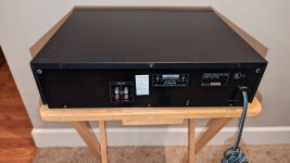
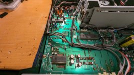
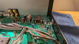
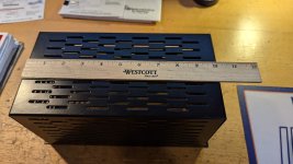
Oopsy...

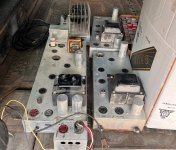
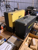
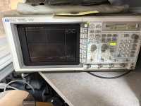
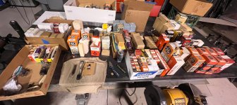
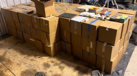
I tripped, fell and accidentally purchased a giant lot of tubes 'n' other goodies. I can't recall how I first caught the tube bug but never the less here I am. Sooooo, now I have a hangar full of tubes of all kinds and conditions. I kinda have an unlimited supply of a variety tubes to play with. While I don't expect to find large lots of the popular tubes, they are popping up here and there. I have have barely scratched the surface though so I have high hopes to find some gems as I make my way through them.

I hope of find fun and interesting ways to use what I find. AF amps, RF amps, power supplies, etc. etc... I am a ham, somewhat of an audiophile (ok, not really) and have a decent understanding of electronics and have been boning up on tube knowledge. My hope is to enjoy the journey of learning more about electronics, "vintage" electronics and tubes 'n' stuff. I think I have most of the basics covered from a tools and test equipment standpoint and I aquired a few chassis with the lot of tubes so now I just need to pick a project and get started.

So by now my reason for being here should be relatively obvious. I need to absorb some of that juicy knowledge from y'all and hopefully share my journey along the way!

Looking forward to it!

Pete...

Attachments

  • IMG_3463 2.JPG
    IMG_3463 2.JPG
    455.1 KB · Views: 70
  • IMG_3466 2.JPG
    IMG_3466 2.JPG
    460.5 KB · Views: 72
  • IMG_3467 2.JPG
    IMG_3467 2.JPG
    803 KB · Views: 72
  • IMG_3471 2.JPG
    IMG_3471 2.JPG
    628.6 KB · Views: 73
  • IMG_3485 2.JPG
    IMG_3485 2.JPG
    559.8 KB · Views: 69

I want engineering drawing for LP12 sub chassis

Hi 👋everyone
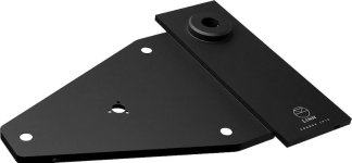
My uncle always talked about how he is going to build a lp12 subchassis one day, but it's been years already. So I would like to spend time and build it for him as a surprise.

After searching online I can't find any schematic for the actual subchassis itself.

Can someone help provide me a schematic for it so that I can mill it?

I am studying for bachelor of engineering, so I have access to tools but I don't have much knowledge. Please tell me anything I needed to know

Sincerely
friendlyengineer

Attachments

  • images (1) (2).jpeg
    images (1) (2).jpeg
    2.9 KB · Views: 89
  • images (1) (1).jpeg
    images (1) (1).jpeg
    13.9 KB · Views: 88
  • Like
Reactions: dazcwl

2024 Subaru Outback with HK - audio upgrades

Overall, I am pleased with the sound of the upgraded HK system in my 2024 Outback Touring. I would describe the sound as balanced and enjoyable (after tweaking the 3 band eq to my liking). It is just lacking punch and only plays so loud, lacking upper detail and after 2/3 - 3/4 volume it just breaks apart and goes to crap. Now, after 1 year of driving around, it is time to do some upgrades and get it to the next level. The HK system is basically a black box but I have found some good info on the Outback forums.

Lets get to what I have done so far and what I am planning in the future.

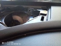
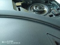
I have replaced the left and right factory mid/tweeters with JL Audio C2-350x 3.5" coaxials. This was a PITA as the factory locations do not allow a 3.5" to drop into place. The factory speakers are mounted to a plastic base which is just too small for a 3.5" speaker. Time to pull out the dremel with the flex shaft extension and start grinding away. I would give this a high difficulty rating (luckily no damage to my dash or windshield)
These sound pretty darn good I have to say! I was a bit worried as the HK amp/DSP is tuned for the OEM speakers. Definitely an improvement from the crappy OEM speakers.

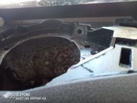
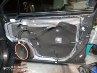
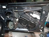
I pulled the front door panels off and applied sound dampening pretty much everywhere. But first the plastic membrane had to be carefully taken off.
I first instlalled JL Audio C1 - 650s (93 dB; just used the woofers) and then later replaced them with Hertz C-165 woofers (93 dB) not sure why I didn't use the C2-650 to match with the dash speakers (oh right they seemed pricy). As I found out later by others in the Subaru forums, a higher sensitivity speaker works best here. Both the JL and Hertz can't match the levels I am getting from the dash speakers. (need a bit more midbass) This is the problem you get when dealing with a black box. So that raises the question whether I install an aftermarket amp/dsp. I will probably add this design in a future post if i plan on going that route.

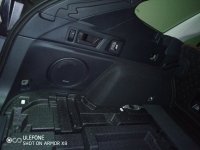
A was brave enough to pull apart the car to get at the OEM subwoofer. You have to remove the rear back seat bottom (pretty easy - 2 clips and pull up) Then unbolt the back seat section on the driver's side where the seatbelt runs through. Then pop away the panels, remove the rear tie-down points (4 or 5) and 2 other screw/bolts that are hidden away Then the whole plastic panel pulls off and then you can access the subwoofer.
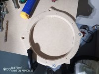
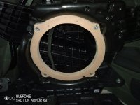
I replaced it with an AudioFrog GS8ND2 8" thin-line subwoofer. I just had to make a spacer/bracket out of 3/4" mdf to mount the sub to as the factory holes don't line up. There is definitely some improvement from the OEM sub; namely cleaner/less muddy bass. But it is lacking the whole point of a subwoofer in my opinion.
Again...
The black box...
need more juice to get things moving.
Next step will be installing a link1000.1mini amplifier. My plan is to install it in the rear cargo area to the left of the spare tire. Will be cutting out the styrofoam that lies below the cargo bed so that it will retain the factory look. Autoharnesshouse.com makes some harnesses that I will be using. I plan on tapping into the front door speaker signal as it provides a full range signal and is prob not as adultered as much as the sub signal. The 1000.1.mini has a built in low pass and parametric EQ for my tuning needs.

Okay, thats's it for now. Sorry for the long post. Check out the pics as well.

Attachments

  • IMG_20241013_125059_533.jpg
    IMG_20241013_125059_533.jpg
    352.8 KB · Views: 133
  • IMG_20241013_125156_360.jpg
    IMG_20241013_125156_360.jpg
    445.2 KB · Views: 122
  • IMG_20241013_132654_251.jpg
    IMG_20241013_132654_251.jpg
    387.3 KB · Views: 122
  • IMG_20241013_132725_238.jpg
    IMG_20241013_132725_238.jpg
    396.4 KB · Views: 115
  • IMG_20241013_172307_913.jpg
    IMG_20241013_172307_913.jpg
    1,014.6 KB · Views: 110
  • IMG_20241018_191826_011.jpg
    IMG_20241018_191826_011.jpg
    612.4 KB · Views: 115
  • IMG_20241018_193952_596.jpg
    IMG_20241018_193952_596.jpg
    443.2 KB · Views: 115
  • IMG_20241018_212604_443.jpg
    IMG_20241018_212604_443.jpg
    709.7 KB · Views: 108
  • IMG_20241018_223457_230.jpg
    IMG_20241018_223457_230.jpg
    581.5 KB · Views: 108
  • IMG_20241024_221444_627.jpg
    IMG_20241024_221444_627.jpg
    345.7 KB · Views: 108
  • IMG_20241024_221804_732.jpg
    IMG_20241024_221804_732.jpg
    414 KB · Views: 118
  • IMG_20241024_225530_942.jpg
    IMG_20241024_225530_942.jpg
    708 KB · Views: 116
  • IMG_20241024_230615_195.jpg
    IMG_20241024_230615_195.jpg
    470.4 KB · Views: 146

Linn Sondek DIY mods that work

Are there any, or should we believe the view an LP12 is like an old violin?

despite reading many threads, views on the commercial products vary widely. As for DIY mods, damping is thought to be the wrong principle for its design, or so it is said.

But in which case there seems little on diy stiffening.

Mine has Valhalla/ Basik LVX.

Replacing the psu with an external one is an obvious path but are there no mechanical DIY projects that work?

Anyone had any success with table or arm mods?

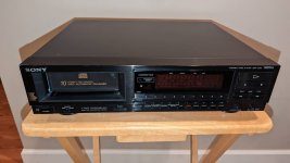
For Sale Sony CDP-C100 10 Disc CD Player w/TDA1541 Chip

For Sale: Sony CDP-C100 with Philips TDA1541 chip. I installed a socket on the motherboard so the chip can be swapped. Original TDA-1541A chip replaced with the TDA1541.

Works great, but some of my CD that are in bad shape do occasionally skip, but good CD have no issues...

Would like to sell locally to confirm proper operation. Pickup in West suburb of Chicago.

Attachments

  • 00j0j_5Dj5Em65wGo_0CI0lM_1200x900.jpg
    00j0j_5Dj5Em65wGo_0CI0lM_1200x900.jpg
    58.8 KB · Views: 282
  • 00h0h_3SKBQ5cTnlI_0CI0lM_1200x900.jpg
    00h0h_3SKBQ5cTnlI_0CI0lM_1200x900.jpg
    55.9 KB · Views: 275
  • PXL_20230706_144702200.jpg
    PXL_20230706_144702200.jpg
    386.5 KB · Views: 313
  • PXL_20230706_144739955.jpg
    PXL_20230706_144739955.jpg
    309 KB · Views: 264

Jadis Orchestra Tube Amp cage

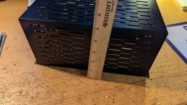
Bought this Amp cage thinking it would fit my amp and as my luck would have it, a little too short width-wise... so up she goes...

Its a tube cage for a Jadis Orchestra tube amp.

Bought it for $50, so $50 + ship

Attachments

  • PXL_20240629_190431933.jpg
    PXL_20240629_190431933.jpg
    259.5 KB · Views: 116
  • PXL_20240629_190447197.jpg
    PXL_20240629_190447197.jpg
    271.2 KB · Views: 126
  • PXL_20240629_190459093.jpg
    PXL_20240629_190459093.jpg
    342.4 KB · Views: 119

For Sale Pro-Ject Integrated Stereo Amp Box RS (Hypex + 6922 Tube pre)

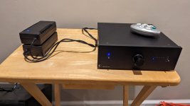
For Sale: Pro-Ject Stereo Amp Box RS Integrated Tube based amplifier.

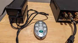
Many inputs including XLR. Pair of 6922 tubes driving a pair of Hypex UCD 180LP based amplifiers. Works perfectly, but does not come with stock +48vdc / -48vdc power supply. A DIY power supply was made for this amp (more amps than stock), and is included.

Case has some wear and tear form previous owner, but functions as intended.

Comes with aftermarket universal remote programmed for power on/off, volume up/down, and input selection.

$525 + ship.

Attachments

  • PXL_20231219_211402826.jpg
    PXL_20231219_211402826.jpg
    221.3 KB · Views: 229
  • s-l1600.jpg
    s-l1600.jpg
    129 KB · Views: 227
  • PXL_20240821_164348657.jpg
    PXL_20240821_164348657.jpg
    399.8 KB · Views: 221
  • PXL_20231219_211455761.jpg
    PXL_20231219_211455761.jpg
    323.9 KB · Views: 193
  • Manual_Stereo-Box-RS.pdf
    Manual_Stereo-Box-RS.pdf
    203 KB · Views: 53

DIY PCB repair books/ adult classes

I’m trying to teach myself a new skill/trade and I was wanting to know if there any go to books that I can read on PCB repair. It’s something that I have always been interested in and I thought I can be a good hobby for me to pick up. I have engineers on both sides of my family and it was always my dream to go to college for engineering but poor life choices I’m my early years ruined that. If I could make it work I’d love to take some adult classes for it as well if anyone knows of any in the Philadelphia region. An apprenticeship at a local shop for a few hrs a week would also be amazing.

Any help would be greatly appreciated.

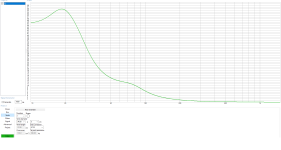
Nearfield vs outdoor measurement on Tham10 and ThMini-clon

Hi.

Ive tried/tested/thought about many different (compact-ish) sub-configurations around 10" and 12".
The scope is not HiFi or accuracy, More like an exercise in output vs size vs price.

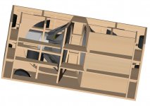
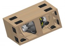
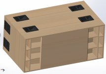
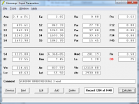
Here I would like to present the measurments on 2 different subs (one of them, maybe not actually in the "sub"-category...): a Tham10 and ThMini-inspired Tapped Horn with a 12". The ThMini-inspired horn is 40x60x60cm outside with 20mm ply and thus around 100L actual internal volume. A Tham10 is approx half the volume.

Ive measured both like this:
  • Indoors in my basemest right at the horn-mouth
  • Outdoor at about 1m distance. Sub and mic placed on a piece of ply, on the lawn. Some buildings 5-10m away. Windy day, and thus high noise-floor.
The measurments are imported to google-sheets and adjusted to be around the same level for indoor vs outdoors. Raw data and a smoothed version shown. My interest was not absolute level, but response. My measurments are very crude, but Im supprised how well the indoor response line up with the outdoor measurments.

If the measurements are correct, the Tham10 drops off at 70Hz, but it works supprisingly well for playing very loud modern pop/dance. - yes the lowest notes are missing, but I very much doubt that most people notice. As far as I remember the measurments for both tapped horns were at similar settings and if thats correct the Tham 10 is as efficient as the ThMini above 70Hz. - but much, much smaller.

Maybe of interest to some of you. Please share thoughts and ideas.

ThMini clone with a 12-280/8-W from Thomann: Thin line: raw data, Thick line: smoothed by google sheets.

1743186752823.png


Tham 10 with a Car-sub from Eminence (very solid driver): same setup as above
1743186998405.png
  • Like
Reactions: Booger weldz

Pairing Markaudio CHR-120 with a tweeter

Hello everyone,
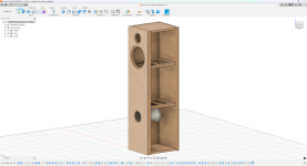
I've been designing a tower speaker lately with the chr-120 and the sb acoustics sb29rdc-c000-4. The main reason why I'm pairing a tweeter to a fullrange is because the off axis response of the chr120 alone is not the best and I wanted to make a tower that would sound nice in a good range of positions in my room.

The design is a 60 L ported box, the vent is 18,3 cm long and 9 cm ID, made it so that turbolence is not a problem even at the highest volume the speaker can play.

I started the design by tracing the responses from the manufactures datasheet and modelled this crossover in the image (i attached also a zip with all the files). Since I don't have the speakers in my hand yet and am not prepared to make measurements I was wondering how far off this design would be from reality, especially considering the phases are calculated from vituixcad and in the woofer i set a z offset to match the impulse response calculated by vituix as well.
Since I'm a student and don't have much money to spend experimenting, am I fine designing a speaker this way and getting all the parts, rather than buying parts and changing them later?
I'm open to any kind of advice!

Attachments

  • Project Files.rar
    Project Files.rar
    893.9 KB · Views: 22
  • image.png
    image.png
    537.5 KB · Views: 81
  • Screenshot 2025-03-27 194856.png
    Screenshot 2025-03-27 194856.png
    1,014.8 KB · Views: 77

Question about old mylar cap values

I have a few very old mylars without clear (to me) units, or no unit specified at all.
One reads .001 with 10% and 1KV beneath it.
A second reads 82 with 10% beneath it and 1KV on the other side as it is about half the size of the ".001!"
A third reads .1Z with 10V beneath it.
Looking on the net I found different interpretations of that 'Z:' one stated it was the tolerance, another that the 'Z' meant it was in picofarads.

H E L L L P P!!!

DC speaker protection relays not triggering with DC

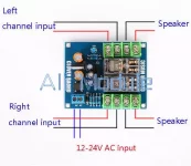
I have added one of these to a dual mono class D amp I built with 2 mono IRS2092 boards. I have tried to check that these work if DC is present by attaching a 1.5v battery to the speaker OUT terminals but the relays are not doing anything. Have I got the wrong idea of how to check that they will work if there is DC present?

Attachments

  • Dual Relay Bd.webp
    Dual Relay Bd.webp
    28.7 KB · Views: 57

Using Castle Winchesters as inspiration for high efficiency system?

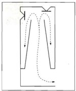
Hi folks, it's been a while since I last posted. I have dabbled with horns and high efficiency for the best part of the last 20 years, bit of an addict you could say, but following a recent house move I have had to 'make do' with a pair of Castle Winchesters... Whilst I miss the air and openness of good compression drivers in the upper frequencies, I must say I am rather taken by how the Winchesters do bass, especially considering their very domestically acceptable size. With the right amp there is a lovely sense of articulation down below (and they go quite low). This has given me ideas for a DIY system using a similar driver layout, i.e. one front firing, one upward firing (as illustrated by the cross section below), but using bigger and more efficient drivers, say 12" or even 15". I have a pair of of 400Hz 2" Stereolab horns waiting in the wings, which I could use for the HF. Any thoughts on which drivers could be made to work in this context would be welcome, or for that matter any feedback from those who have embarked on similar projects 🙂

Attachments

  • Simplified cross section.jpg
    Simplified cross section.jpg
    15.1 KB · Views: 40

DIY Audio Analyzer with AK5397/AK5394A and AK4490

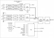
Audio Analyzer with AK5397/AK5394A and AK4490

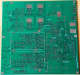
For more than 3 years I have been working on and off (mostly off) designing a high-end Audio Analyzer. Parts of the design have been implemented as separate units. I have finally put the pieces together on one PCB (+ some small existing interface PCB's).

Some of the design goals were:

1. The Audio Analyzer should work as a sound card, enabling use with a wide selection of Audio Analyzer SW packages.
2. The performance should be somewhere between a good high-end sound card and an AP, R&S, SR etc.
3. The performance should approach the limits possible with the ADC and DAC used.
4. It should be possible to use it with any relatively modern PC. This is the reason for choosing a USB interface to the PC. SPDIF/Toslink was considered, but this makes it difficult to use portable PC's.
5. The PC should be electrically isolated from the Analyzer to avoid ground loops and noise.
6. No fan for cooling!

I have selected to use high-end converters from AKM. I have previously made a design based on AK5394A and AK4399. This design shows a very good performance, but it was not ideal in terms of flexibility, due to limitations in the input and output stages. The input stage was a relatively straight-forward design based on OPA1612 and OPA1632. The performance is fairly good, but there is no attenuator, so the input range is limited.
The output stage has a limited drive capability, since it is based on the OPA1632.

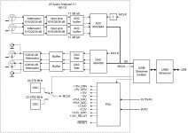
For this design I originally chose the newer AKM converters AK5397 for the ADC and AK4490 for the DAC. After testing the AK5397 I decided to go back to the AK5394A, since the distortion is much lower.
The input stages of the new design are based on a JFET/op-amp combo, with LSK389 and LME49990. This part of the design has been verified on a separate PCB, with attenuator and gain options.
The output stages are based on LME49990 buffered by LME49600.

Main features:
1. AKM AK5394A 24-bit Super High Performance Stereo ADC, 192 kHz sampling, 123 dB SNR (changed from AK5397)
2. AKM AK4490 32-bit Premium Stereo DAC, 192 kHz sampling, 123 dB SNR
3. Dual fully differential inputs and outputs on XLR connectors
4. Dual single ended outputs on BNC
5. AC and DC input switchable
6. 44.1, 48, 88.2, 96, 176.4 and 192 kHz sampling, selected by the Analyzer SW. Potentially 384 and 768 kHz sampling later on (TBD).
7. Full scale inputs from 100 mV (-20 dBV) to 100 Vrms (+40 dBV) in 10 dB steps.
8. Overvoltage protection on the inputs.
9. Full scale outputs up to 10 Vrms differentially (5 Vrms single ended). Can be attenuated to 1 Vrms and 100 mVrms full scale differential output.
10. Single ended output impedance of 50 ohm (changed from 25 ohm)
11. Single ended input impedance of 100 kohm
12. On-board low jitter crystal oscillators (NDK NZ2520SD).
13. Parallel control lines for relays, controlling the attenuators, gains and AC/DC settings.
14. Power supply is integrated on the board (except for the transformer).
15. USB interface is implemented using a completely isolated XMOS based design (changed from USBStreamer).
16. Expansion connector for future digital I/O
17. 20x25 cm PCB

The parallel control lines may be controlled from either manual switches, e.g. rotary switches for the level settings. Other possibilities are to control it with a microcontroller or from the PC via a USB to serial converter. Initially I plan to use manual switches. Update 161222: Settings can be controlled from the PC via the USB interface.

For the power supply a 2 x 15 V and 1 x 9 V transformer is needed. I plan to use an R-core transformer with 2x15 V and 2x9 V, 30 VA, which I have also used for the AK5394A/AK4399 design.
The transformer may be changed to a 2x15V or 2x18V ring core transformer with a slightly modified power supply design. Update 161222: A ring core transformer is used. Primary voltages selectable between 100 to 120V and 220V to 240V.

The isolation between the Audio Analyzer and PC is done with a Master Clock and Isolator, see:
Master clock and isolator for the MiniDSP USBStreamer
Update 161222: The isolation is now part of the XMOS based USB interface.

I have just received the PCB this morning. It will take some time before I will be able to start testing, since I plan to mount the PCB by hand. And I still need to get some of the parts. There are around 750 parts in the design.


I would like to thank Demian Martin (1audio) for his design inputs, reviews and encouragement.

Update April 8, 2017:
GB is now open. See:
GB for RTX6001 Audio Analyzer with AK5394A and AK4490
Update:
Group buy is closed.

Hardware modifications:
To make it easier to find the descriptions of the hardware modifications, I decided to make a list here.

Disassembly and assembly + overvoltage:
GB for RTX6001 Audio Analyzer with AK5394A and AK4490

The overvoltage modification was originally described here:
GB for RTX6001 Audio Analyzer with AK5394A and AK4490

Shield and stability:
DIY Audio Analyzer with AK5397/AK5394A and AK4490

*Moderator note: Second block diagram added at Member's request.*

Attachments

  • JH Audio Analyzer block diagram 150729_01.jpg
    JH Audio Analyzer block diagram 150729_01.jpg
    539 KB · Views: 14,924
  • Audio Analyzer PCB V1.jpg
    Audio Analyzer PCB V1.jpg
    200.6 KB · Views: 14,492
  • JH Audio Analyzer block diagram new with AK5394A.jpg
    JH Audio Analyzer block diagram new with AK5394A.jpg
    544.3 KB · Views: 12,116

CLC vs. CRC

Has anyone direct experience with a FirstWatt clone that has gone from a CRC supply to a CLC supply? I'm talking same amp.If so are there any sonic benefits to doing so? In addition it is a standard 1 toroid,dual secondary,dual FWB rectifiers.I can get a couple of Hammond 159Zl 2.5mH 10A chokes for about $40 each.I can see from simulations quite a reduction in ripple voltage but would there be sonic benefits from this relatively cheap mod?

New Member from 10,000 feet

Hi - I’m a new member from Leadville, Colorado, living at 10,000 feet of altitude. My favorite current hobby is multichannel audio of all flavors, which I particularly enjoy over headphones using a binaural processor (Smyth Realiser A16).

I’ve been working on two projects lately. The first is using an RPI5 + DAC8x + ADC8x (HiFiBerry hats) to convert the 6-channel analog output from my Surround Master V3 to HDMI (my AVR does not have analog inputs). This has been very successful, and I’ll probably go on to explore using CamillaDSP in addition. I’m also using it via Audacity as a replacement for my old Korg D888 8-channel analog recorder.

The second project is exploring ways of extracting HBR audio streams from HDMI. I have an old Unigraf frame grabber which works, but I need to write some code for it to work better. I have a Chinese HDMI input to I2S x4 board that should work but I haven’t had a chance of hooking up my logic analyzer to the 4 I2S outputs yet. I have a Rock Pi 5b that has the necessary hardware, but I need to wait for the mainstream kernel to support multichannel audio in from the HDMI RX (6.15-RC1 is just out and may do the trick; the current kernel driver only supports 2-channel). Finally, I have an HDMI extender over 10 gigE TCP/IP with a managed 10gigE switch that will allow WireShark or similar snooping.

For Sale Faital Pro 8PR200 8ohm x2 - UK

Selling a pair of Faital Pro 8PR200 8ohm drivers for £100, which is 50% of the retail price (£200).

Postage for drivers is £7.00 in the UK

Optional:
I can also include the cabinets for the cost of extra shipping (~£10). These are 10-litre enclosures with a 50mm PVC pipe port (friction fit), Neutrik Speakon connector, and Van Damme cable. Birch ply and MDF. Not perfect nick...

1741706490225.jpeg

1741706490277.jpeg

1741706508122.jpeg

1741706524540.jpeg

1741706554091.jpeg

1741706572918.jpeg

1741706593493.jpeg

1741706610411.jpeg

1741706625689.jpeg

1741706651524.jpeg

1741706700580.jpeg

Crossover capacitor definition

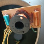
I have a Philips FB297 model 3-way speaker. I wanted to change the electronic capacitors in the crossover circuit, but the capacitor shown in the picture (blue) which I thought was 1uf showed 4.5uf in the measurement. I was surprised. Old blue capacitor with 1u0 written on it. What could be the real value of this capacitor?
Sorry for my English. Thanks for any help.

Attachments

  • old blue cap.jpg
    old blue cap.jpg
    131.7 KB · Views: 57
  • philips fb297.jpg
    philips fb297.jpg
    317.9 KB · Views: 59

Hifisonix nx2-Amplifier: 100W CFA Power Amp

I'm putting this up as a place holder for the new nx2-Amplifier (hereinafter just called the 'nx2') which has been in gestation for some 15 months now. I've had quite a few nudges from various people via email asking about progress. I can understand that some folks have fallen into believing the nx2 is 'vapourware' (if you've worked in semiconductors or software product development, you'll now what that means!).

I started work on this in September 2023, assembled the initial proto and decided it needed more refinement - details which I will cover when the documentation is released. However, things came to a grinding halt when TraxMaker (part of the CircuitMaker CAD suite) stopped working in early 2024. I made the decision to switch to KiCAD (a good move!) and had to redesign the board from scratch. After another 2 proto/dev cycles, the amplifier module PCBs are finally where I want them to be, and quick bench testing shows peak mains hum harmonic components at below -125 dBr reference 60W RMS into 8 Ohms (the power limit of my test lash-up) and <35ppm distortion.

I am currently finalising the PSU +inrush PCB and that will go off for manufacture sometime next week. In parallel with this, the mechanical layout is also being finalised.

Part of the delay in this project has also been the fact that I became a grandfather (yeah, I'm old) for the second time and that entailed putting a lot of stuff on the backburner, and the decision to move closer to family, which we will do in the next 3 weeks. Its chaos here with boxes all over the place, packing etc.

For all of the above reasons, the nx2 won't be completed and released for at least another 2 months, but hopefully you wiol get an idea of whats n the pipeline from this intro. The boards will be available on the hifisonix web shop if you want to build one (but only after I release the completed amp + documentation).

Here are the specs (note these may change once the completed, housed amplifier is re-measured)

1743621828435.png


I've attached some photos below - taken in my workshop today in amongst the packing boxes. (note the front plate is still being assembled so looks a bit manky - it still has to be cleaned, screws fitted and then polished)


IMG_4199.jpeg

Attachments

  • 1743537622240.png
    1743537622240.png
    47 KB · Views: 561
  • IMG_4197.jpeg
    IMG_4197.jpeg
    536 KB · Views: 127
  • IMG_4200.jpeg
    IMG_4200.jpeg
    454.9 KB · Views: 121
  • IMG_4201.jpeg
    IMG_4201.jpeg
    313.8 KB · Views: 124
  • IMG_4196.jpeg
    IMG_4196.jpeg
    547.6 KB · Views: 121
  • IMG_4204.jpeg
    IMG_4204.jpeg
    368.3 KB · Views: 130

"Help for ground loop"

"Hello, as already mentioned in my introduction, I am inexperienced but use the soldering iron for basic tasks, like soldering RCA connectors, etc. Well, I bought a used Tricord Dino phono preamp to connect it to my Rega Planar 2 turntable. As you know, Rega turntables share the arm ground with the left channel. This turntable uses a very cheap direct cable from the arm to the phono preamp. I wanted to modify this cable by cutting it and mounting a metal box under the turntable with female RCA terminals so I could choose the cables based on construction or length. Now, when I turn up the volume without music, there is a hum coming from the speakers. If I touch the box, the hum increases, and it also increases if I touch the arm. The RCA connectors do not come into contact with the metal box. I think I’ve created a ground loop; how can I fix it? Should I connect the left and right negatives to the metal box? Should I connect the metal box to the negative terminal of the phono preamp?

A guide to building the Pass F4 amplifier

Building the Pass/Firstwatt F4

This is a fantastically good sounding amp - read more about it here before staring;

https://www.firstwatt.com/wp-content/uploads/2023/08/prod_f4_man.pdf

The thread at DIY audio -

http://www.diyaudio.com/forums/pass-labs/97540-f4-power-amplifier.html

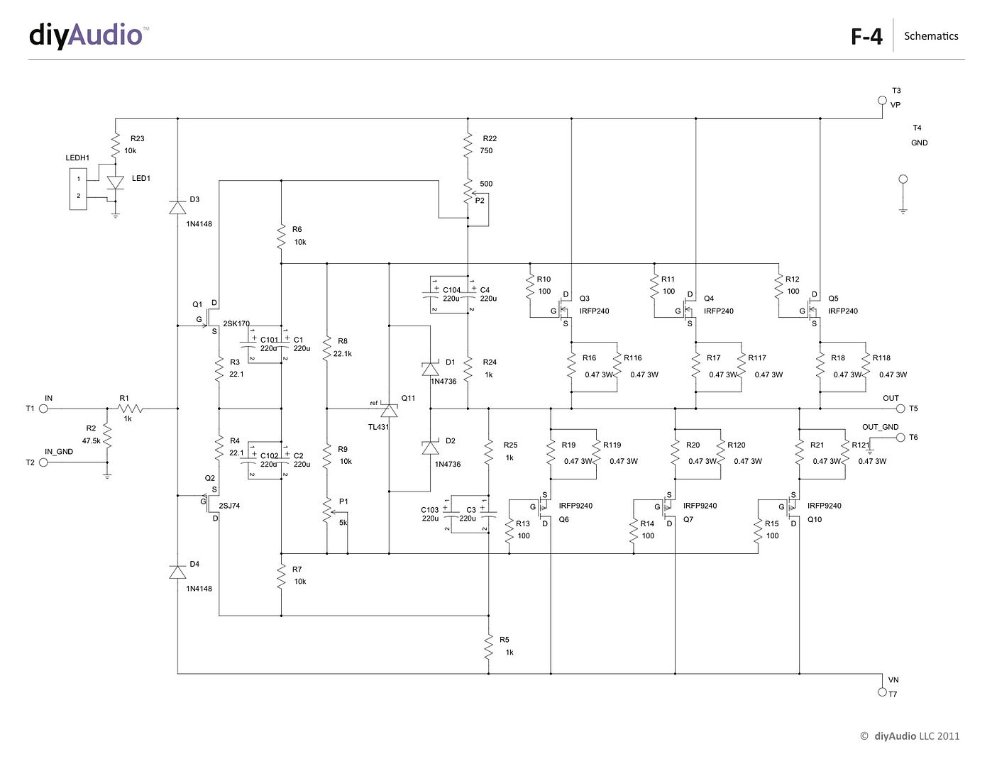
And this the the corrected schematic (The schematic in the Firstwatt article has a typo, also this one agrees with the PCB)

P-F4-1V20-schematic_zps32c28b0a.jpg


Here you will find a build guide for the Pass / Firstwatt F4 power amplifier using PCBs and chassis from the DIYaudio store.

The 5U 'BIG Amp Chassis' is shown, because that's the one I have. It will fit comfortably in a 4U 'Jack of all chassis' and have enough heatsink as well.

~~~~~

There are plenty of places that you could start, but for the sake of illustration let's begin with the heatsink assemblies -

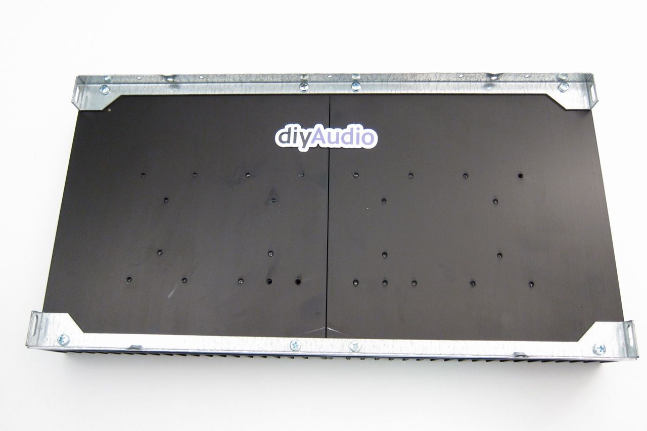
IMG_1391_zps4ef8a39d.jpg


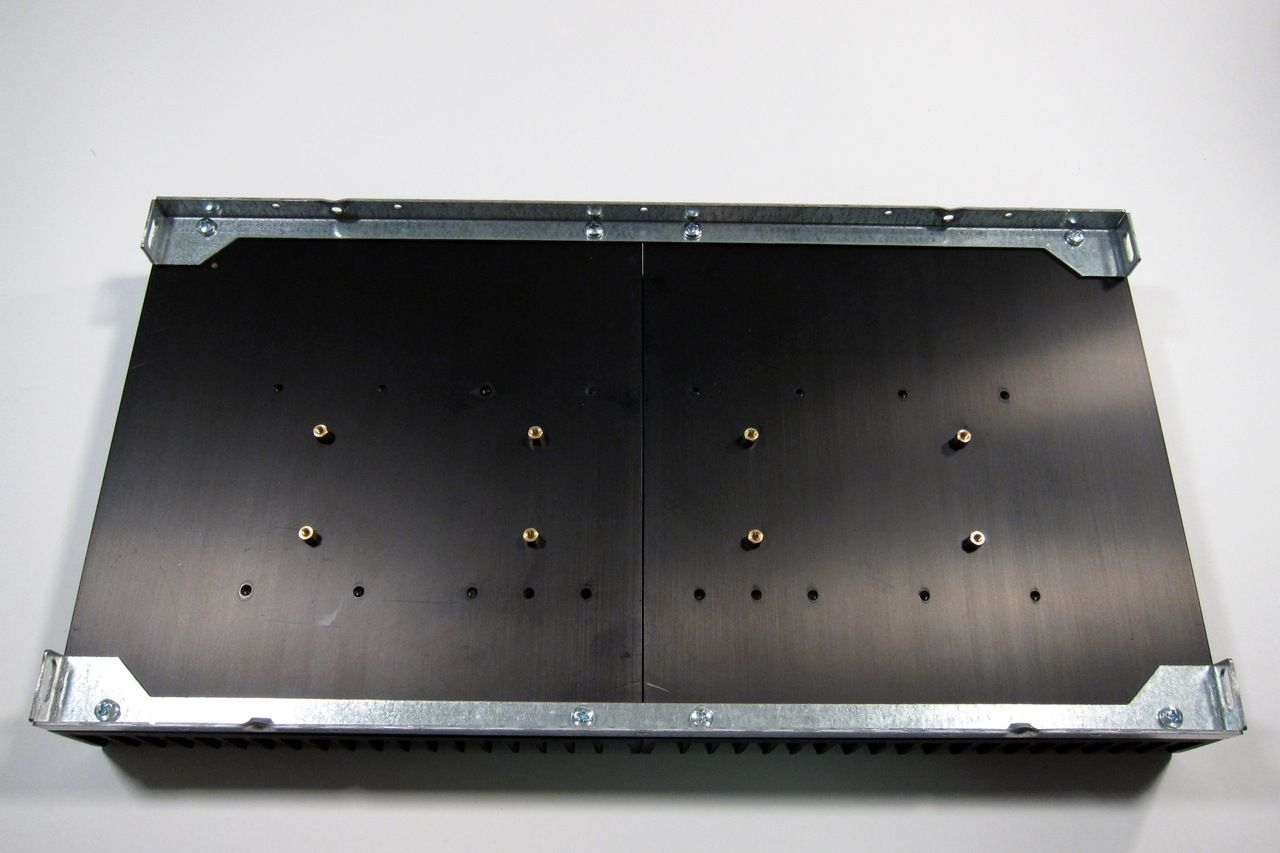
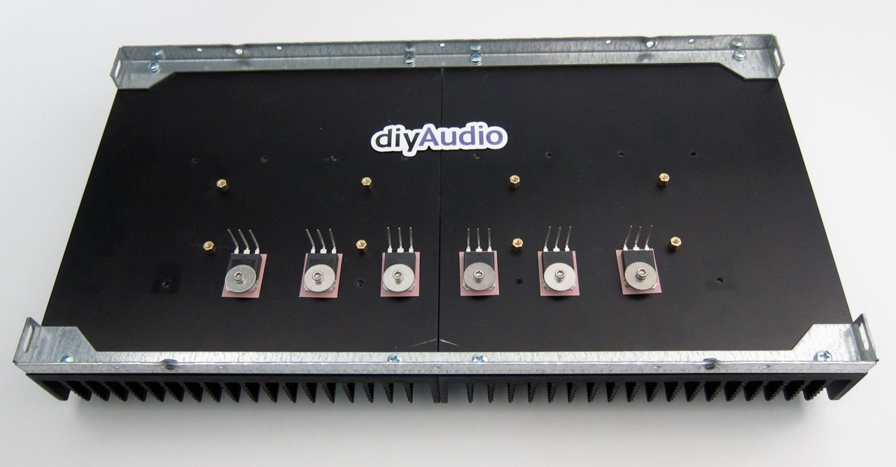
This is the heatsink(s) from the 5U 'BIG Amp Chassis' It has a mirror-imaged set of pre-drilled heatsinks and brackets to hole them together and make a mounting point for the rest of the enclosure. The 4U is similar, but the heatsink is a single piece.


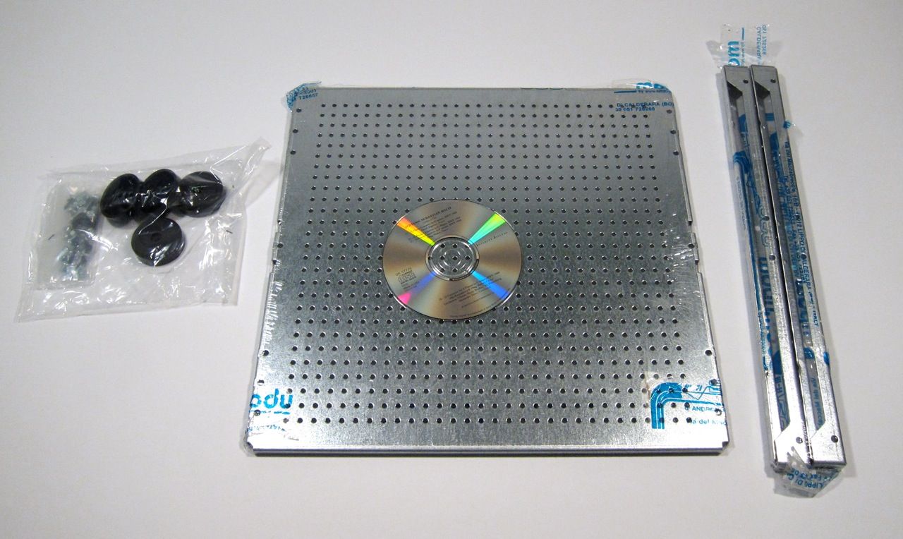
IMG_1366_zps82f8a4cd.jpg

This build will also utilize the 'DIY friendly' baseplate, here shown with the feet and hardware, and also the heatsink's brackets.

An externally hosted image should be here but it was not working when we last tested it.

There is a hardware package available for the pre-drilled back and heatsinks, including input and output jacks, IEC module, and hardware for the PCB and heatsinks.

IMG_1352_zps9fb0c96c.jpg

The contents of the hardware bag.

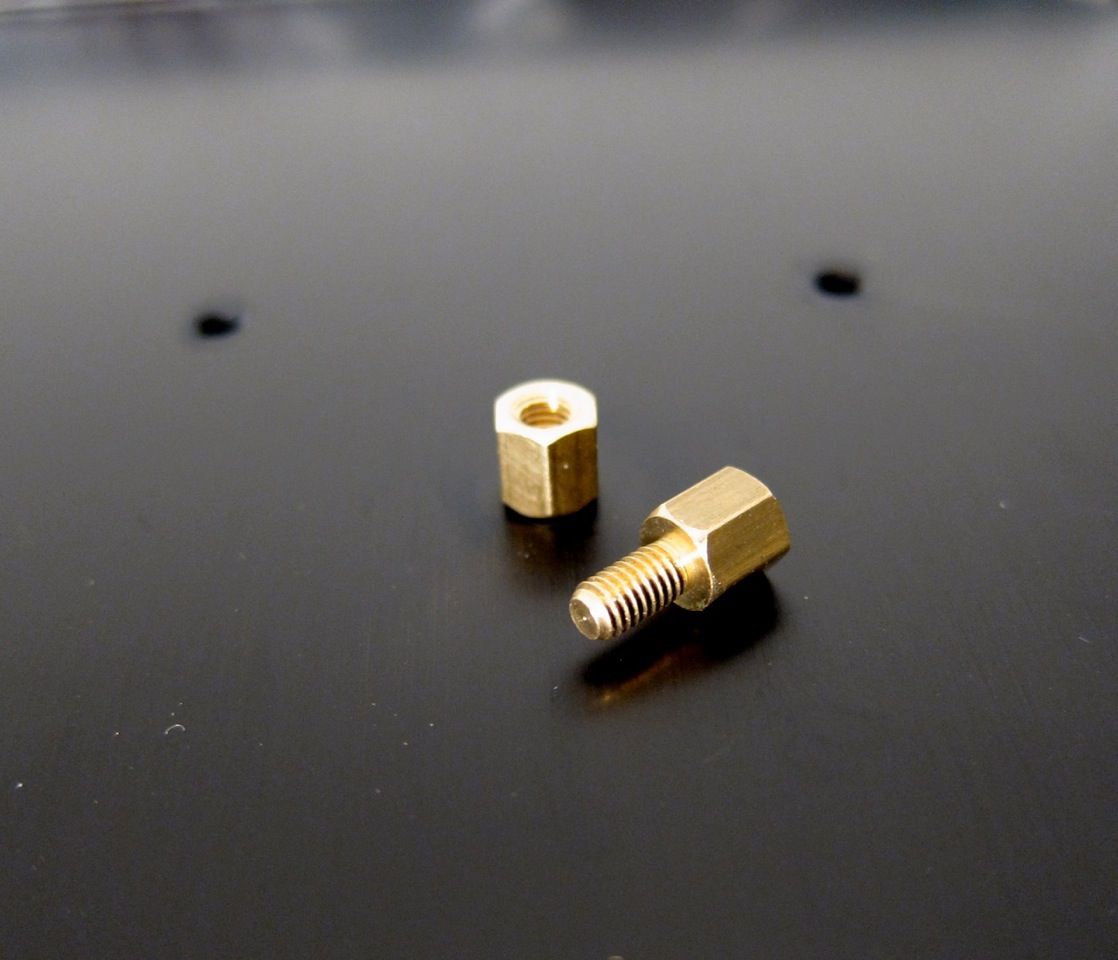
IMG_1393_zps85a2e08a.jpeg

Using the brass PCB standoffs, install them into the PCB mount holes as shown, to get the following pattern;

IMG_1394_zpsf97a8602.jpg

Now there is a place to mount the amplifier PCB

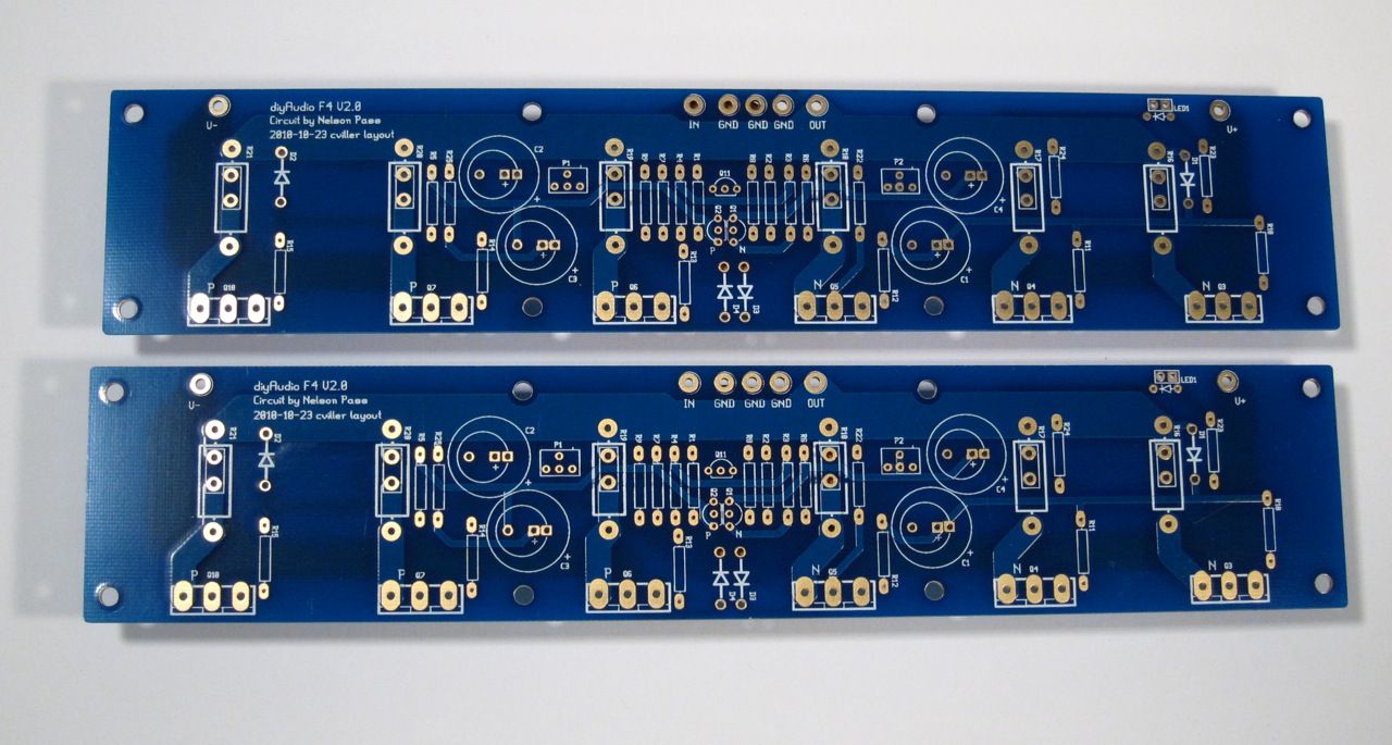
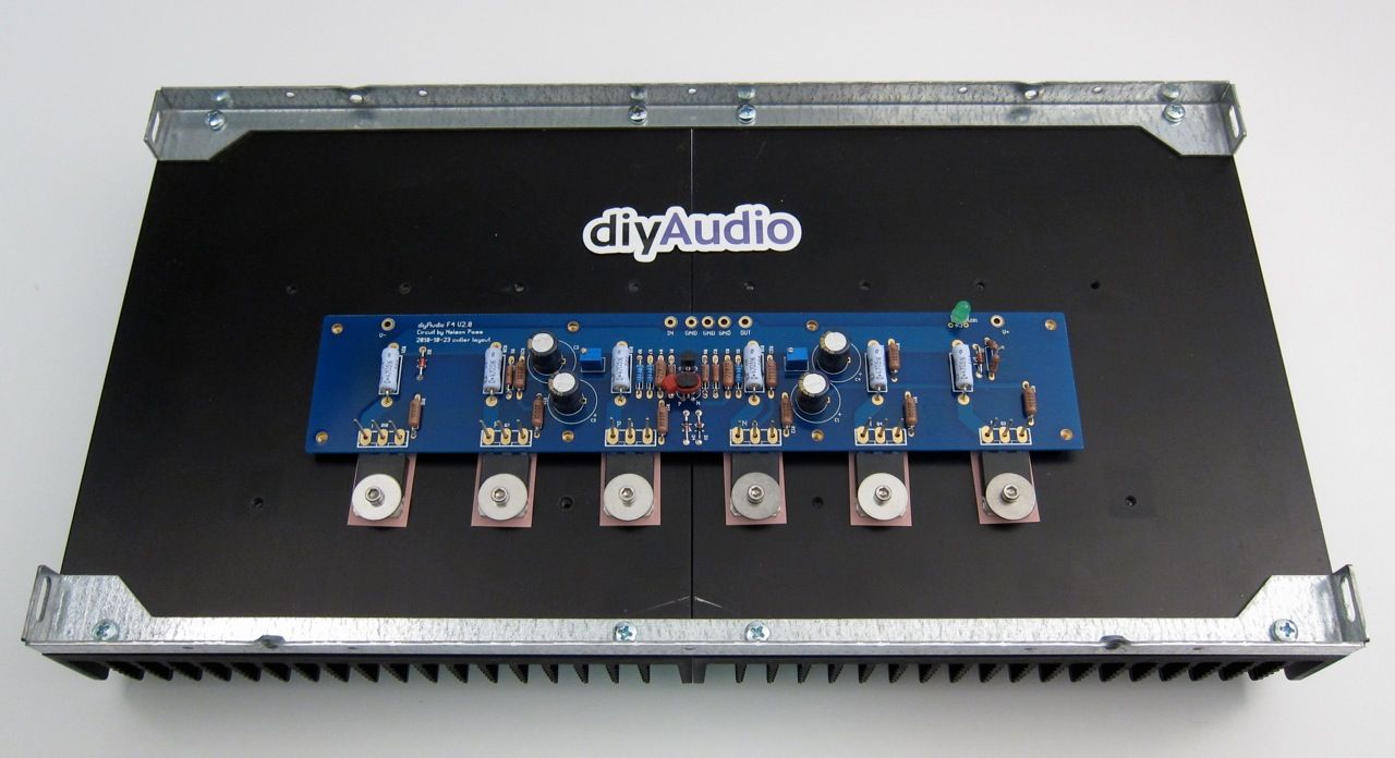
IMG_1328_zps1544a1a0.jpg

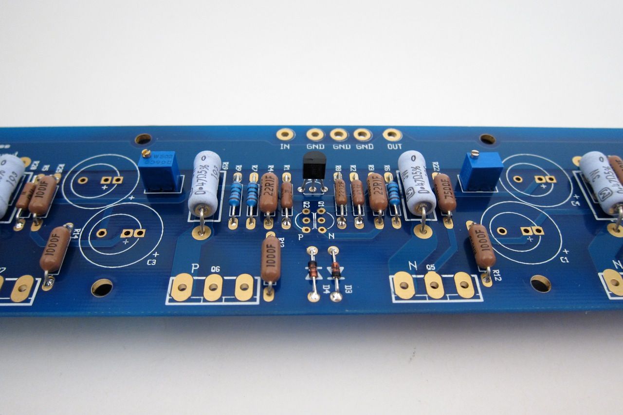
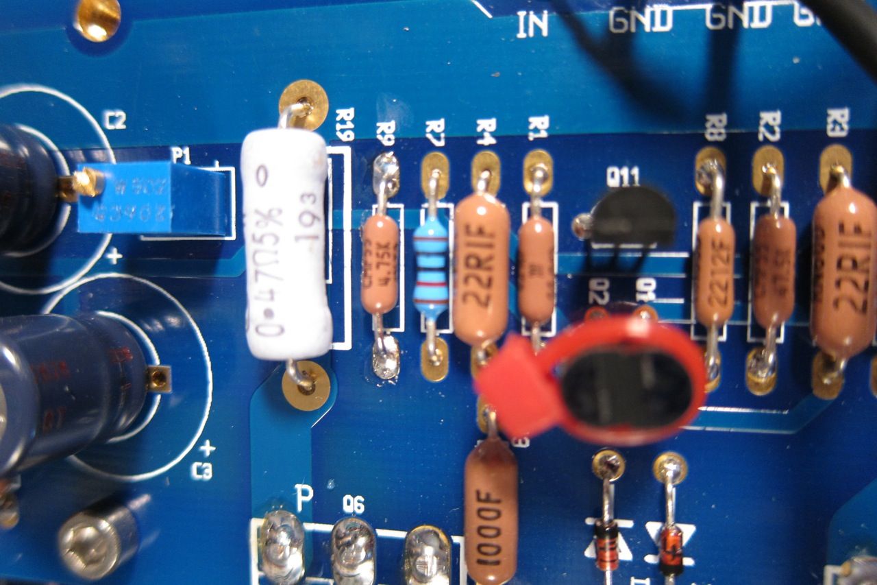
Speaking of PCB, it's a very nice layout, plenty of room, and the ability to use many sizes of resistors and caps. This is the front.

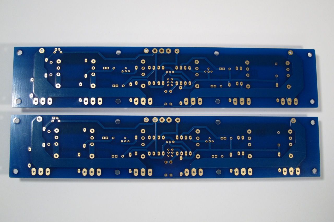
F4PCBback_zps5890d195.jpg

Here is the back.

IMG_1474_zps77bafab7.jpg

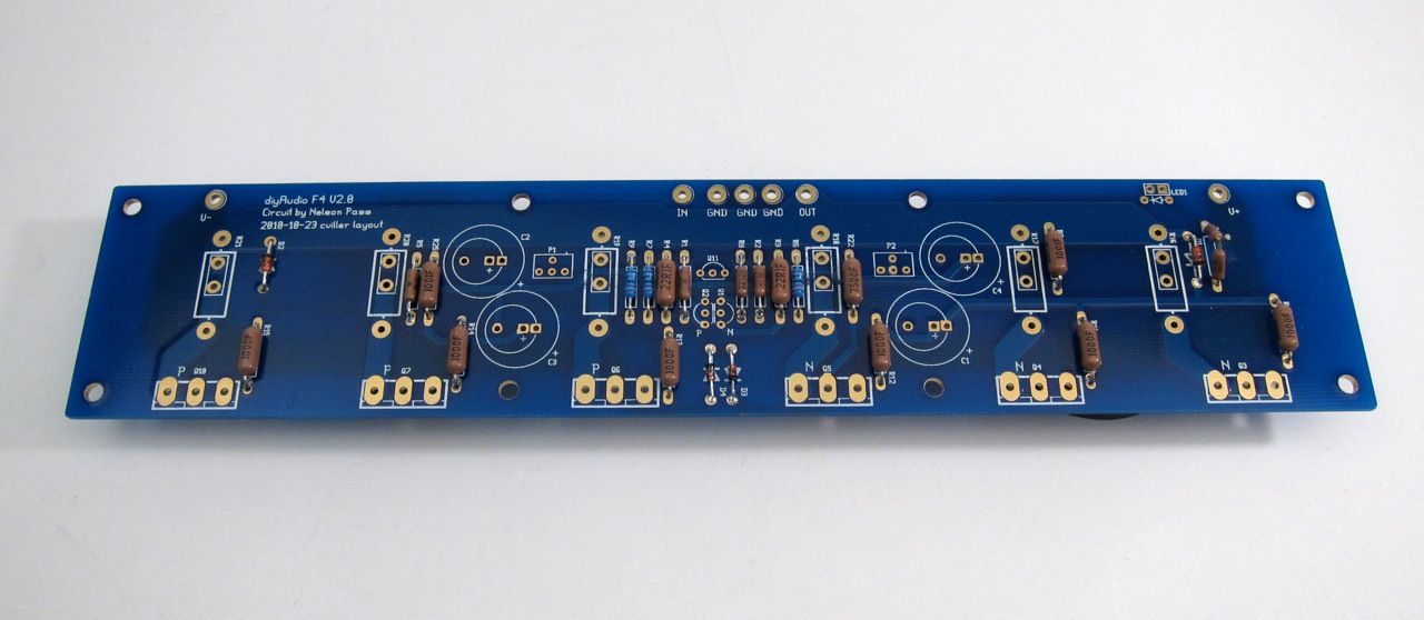
Stuffing the PCB should be done in the usual order, from smallest device to biggest - so that would be diodes and resistors first.

Of note, I got the bigger (Dale/Vishay RN60) resistors to see how they would fit on the PCB. They are the size of the PRP resistors that are quite popular amongst the fancy parts crowd. They are great everywhere except the row flanking the small transistors right in the middle. They don't fit there side by side. You could mount them soldier style, or just mix in a few smaller resistors like I did. Or just get RN55's. They are the smaller size.

IMG_1477_zps30cf4d2c.jpg

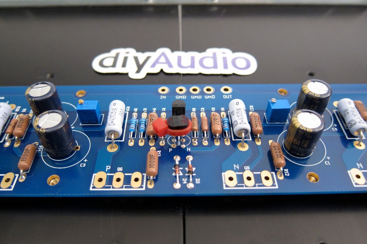
Pots and transistors next. (yes, I didn't stuff the input pair when the photo was taken…)

IMG_1489_zps65e7fd6f.jpg

Ah, there they are.
The ziptie is just to help their thermal tracking.

IMG_1480_zpsf8e420df.jpg

And finally the capacitors.

IMG_1486_zps795ceade.jpg

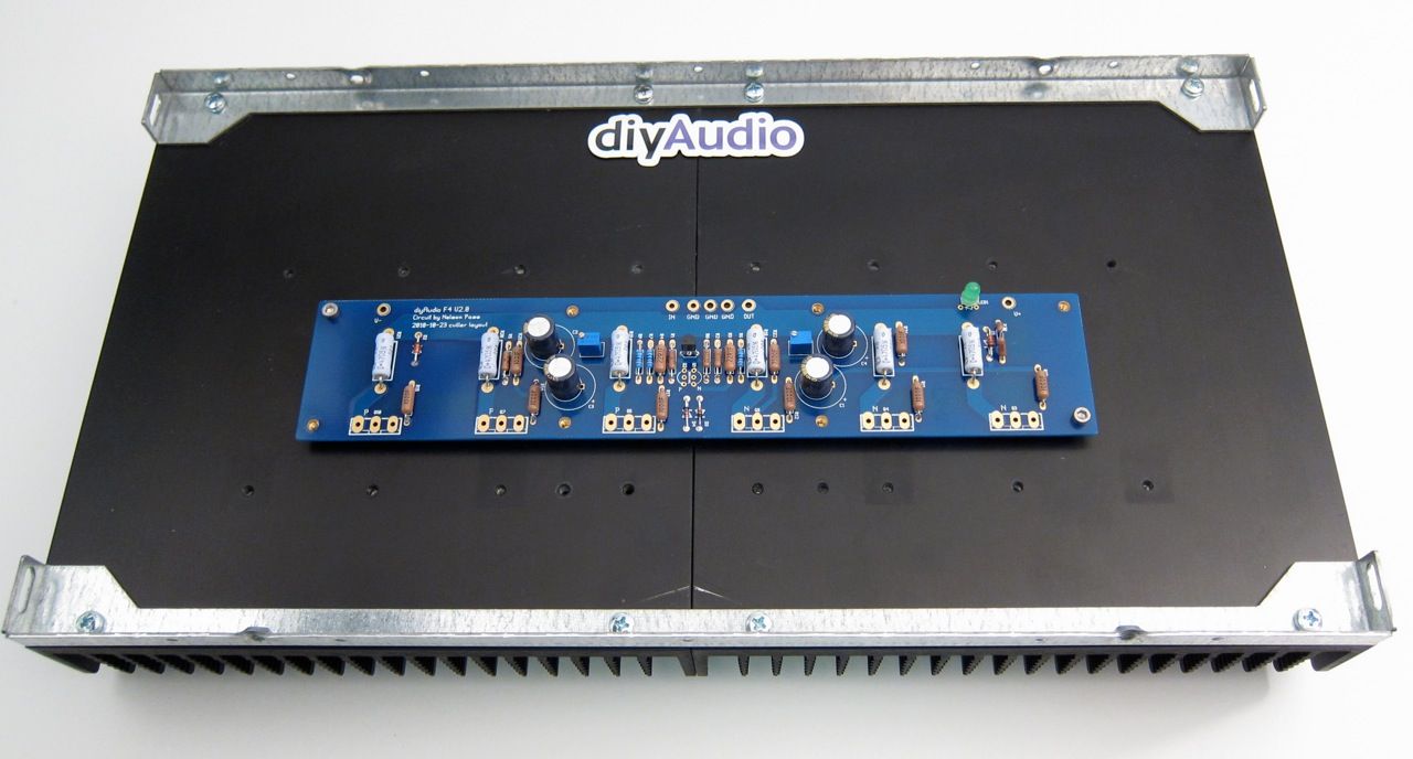
There is a top and bottom to the Universal Mounting Spec holes, the board mounts as shown

IMG_1494_zps3359f3f7.jpg

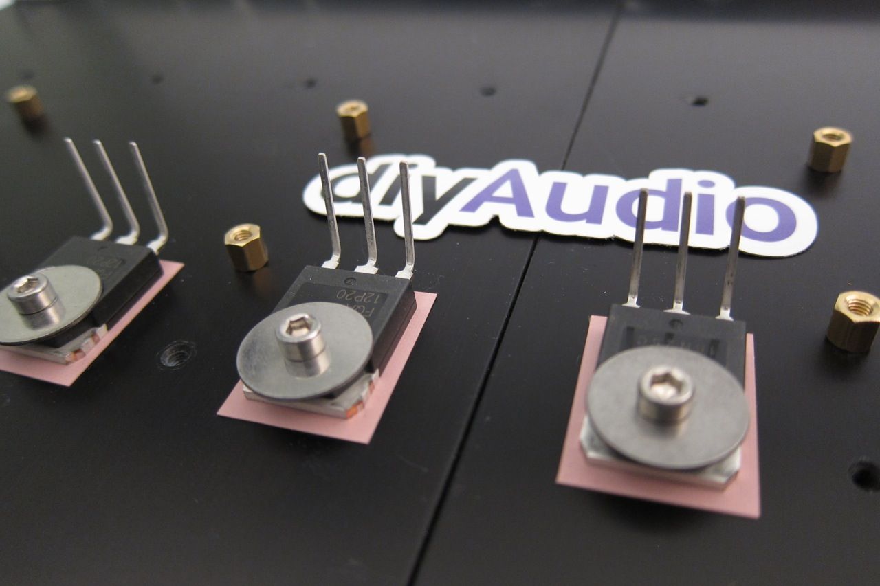
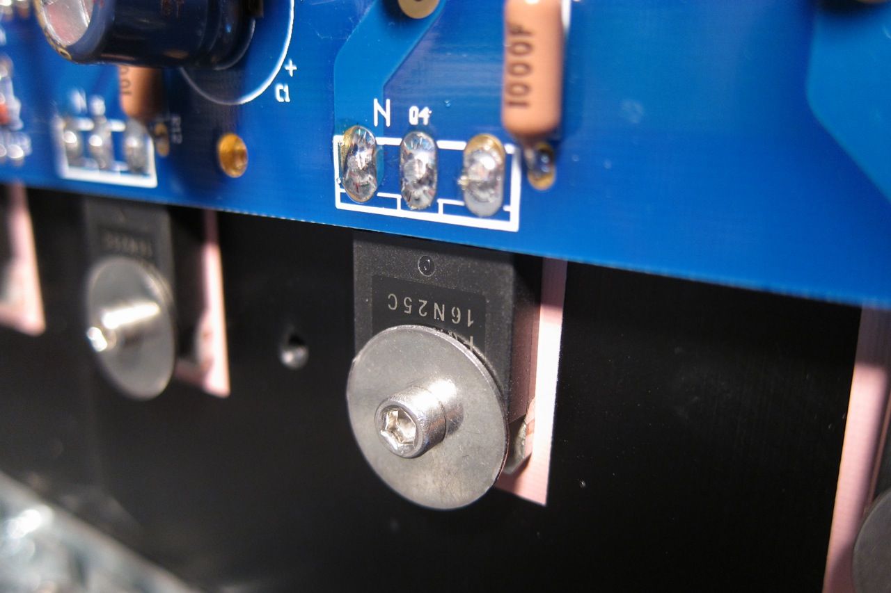
I find it helpful to bend the leads of the transistors first, and mount them (a little bit loose) to the heatsink.

IMG_1492_zpsdec762b0.jpg

Like this

IMG_1490_zps1192f349.jpg

And then mount the PCB. You can snug all the screws down and then solder and trim.

Ok, now lets move on to the Power Supply.

PSUboard_zps616b983c.jpg

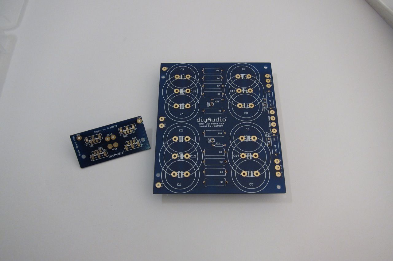
Here is a photo of the PSU board, I am going to use integrated bridge rectifier blocks, so you need to remove the part of the PCB that mounts the diodes. The new PCB, not quite yet available at the time of this writing, will have a similar feature with the diodes, as well as room for more/bigger capacitors.

9c96c03e-67e2-4c92-8538-8d219c9ab64e_zps30c7bdad.jpg

As always, stuff the small components first - the light blue resistors are the filter resistors, the darker ones with the teflon are the bleeder resistors, and the small ones are for the LEDs.

This PSU board is the exact same DIYaudio PSU board, just without the top blue soldermask.

PSUfull_zpsd50e6012.jpg

This shows the INPUT edge (from the diode bridges)

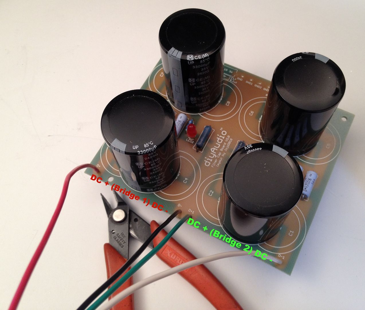
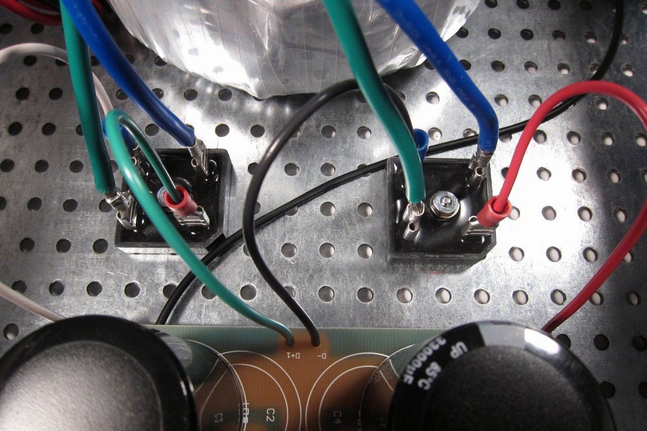
The capacitors are Panasonic T-UP 33,000uf 35V

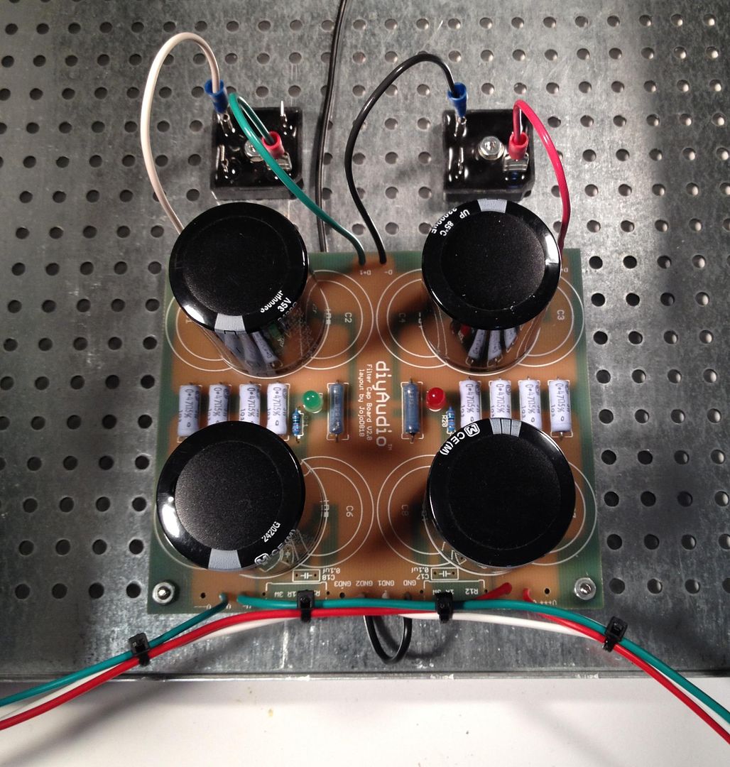
bridges_zpsbec07865.jpg

Connecting the bridges to the PCB

PSUonChassis_zpsf0ac7805.jpg


b2a3196d-cd27-413e-91d8-416854498ff7_zps6e21e4c3.jpg

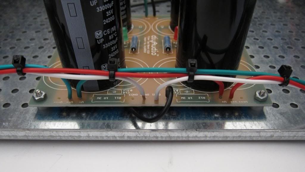
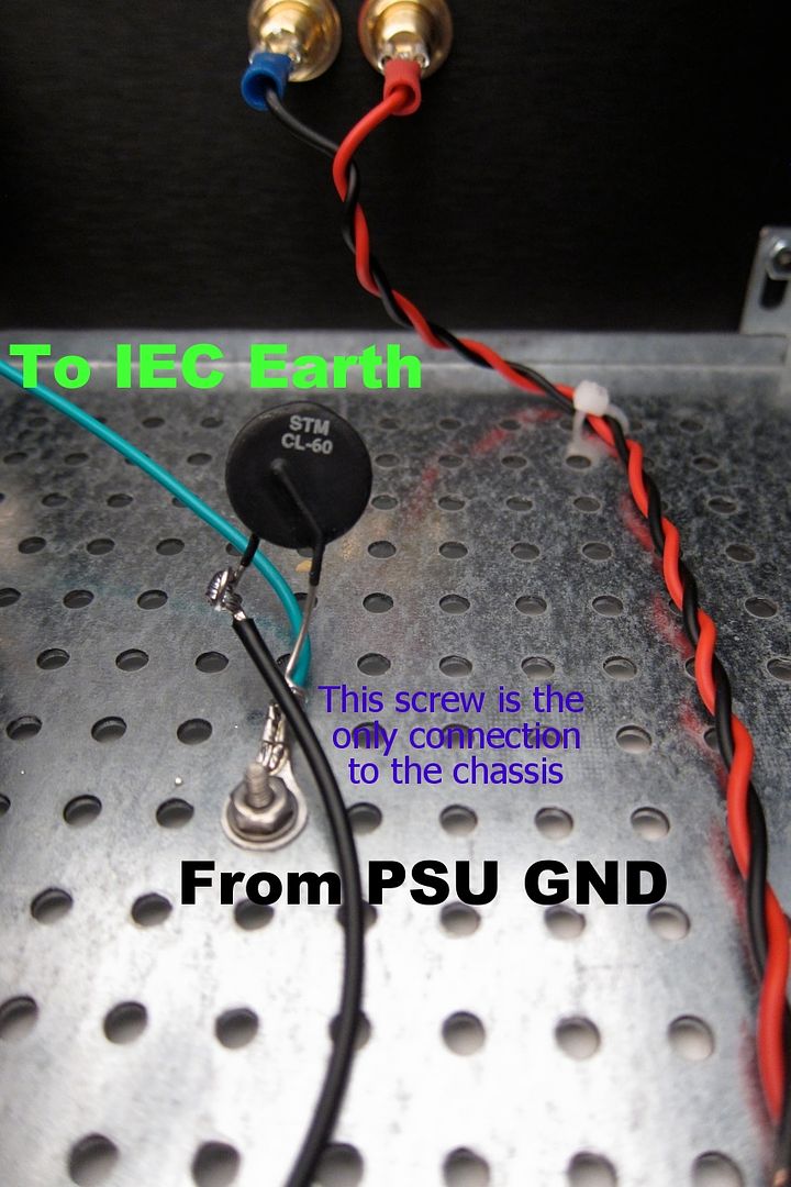
This is the OUTPUT edge of the PSU - the colors are
Red V+
White GND
Green V-
The black connects the PSU GND to the CL-60 to the chassis.

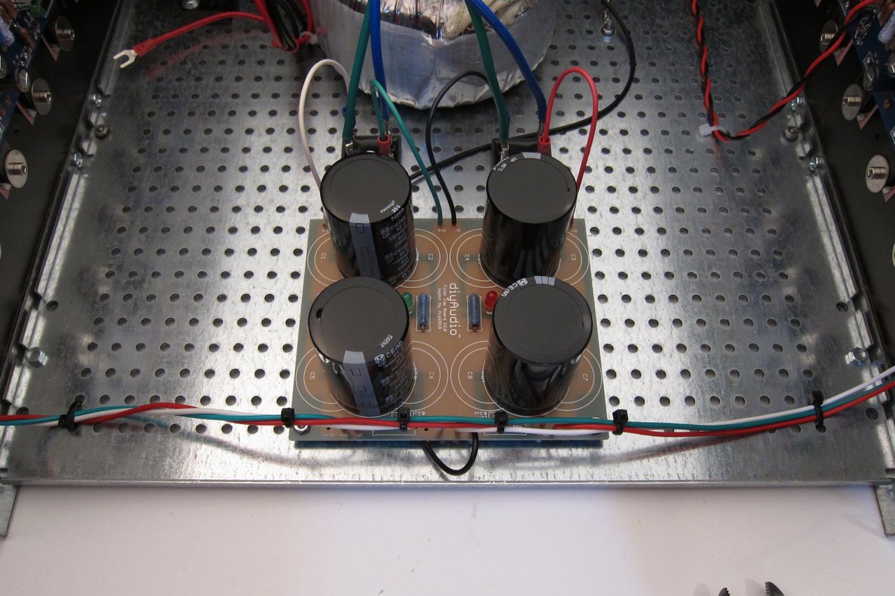
IMG_1496_zpsd0648203.jpg

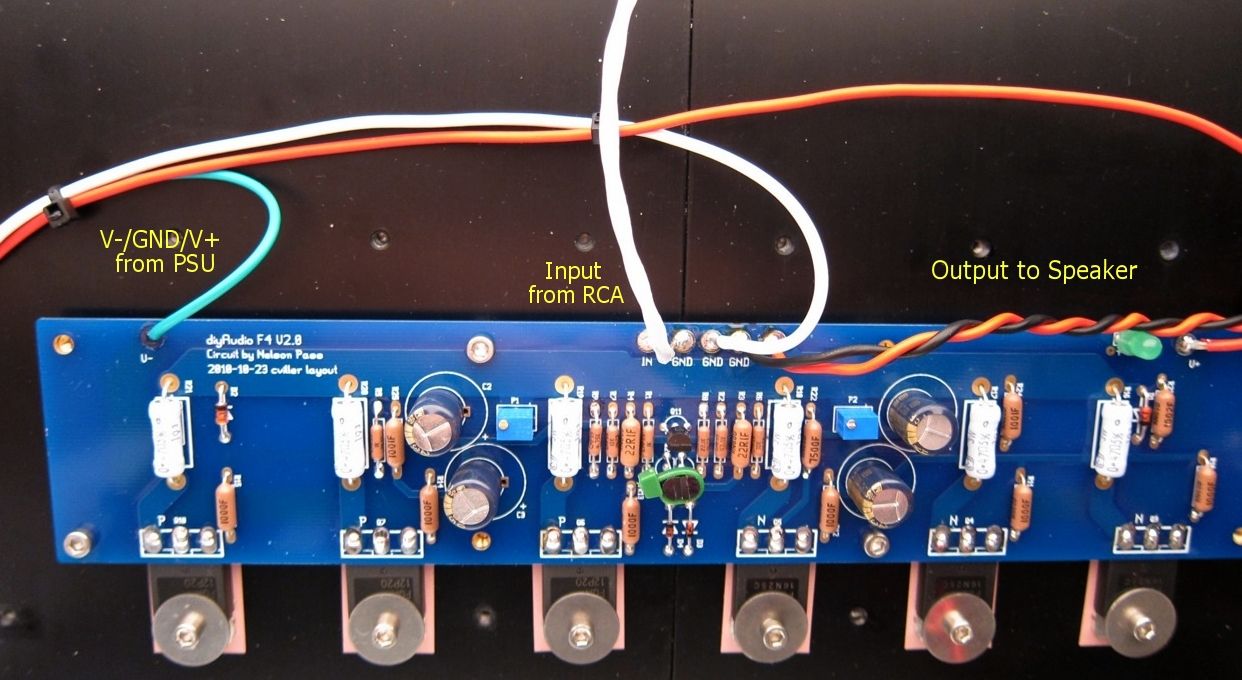
The wiring from the PSU to the amp PCB is clearly shown.

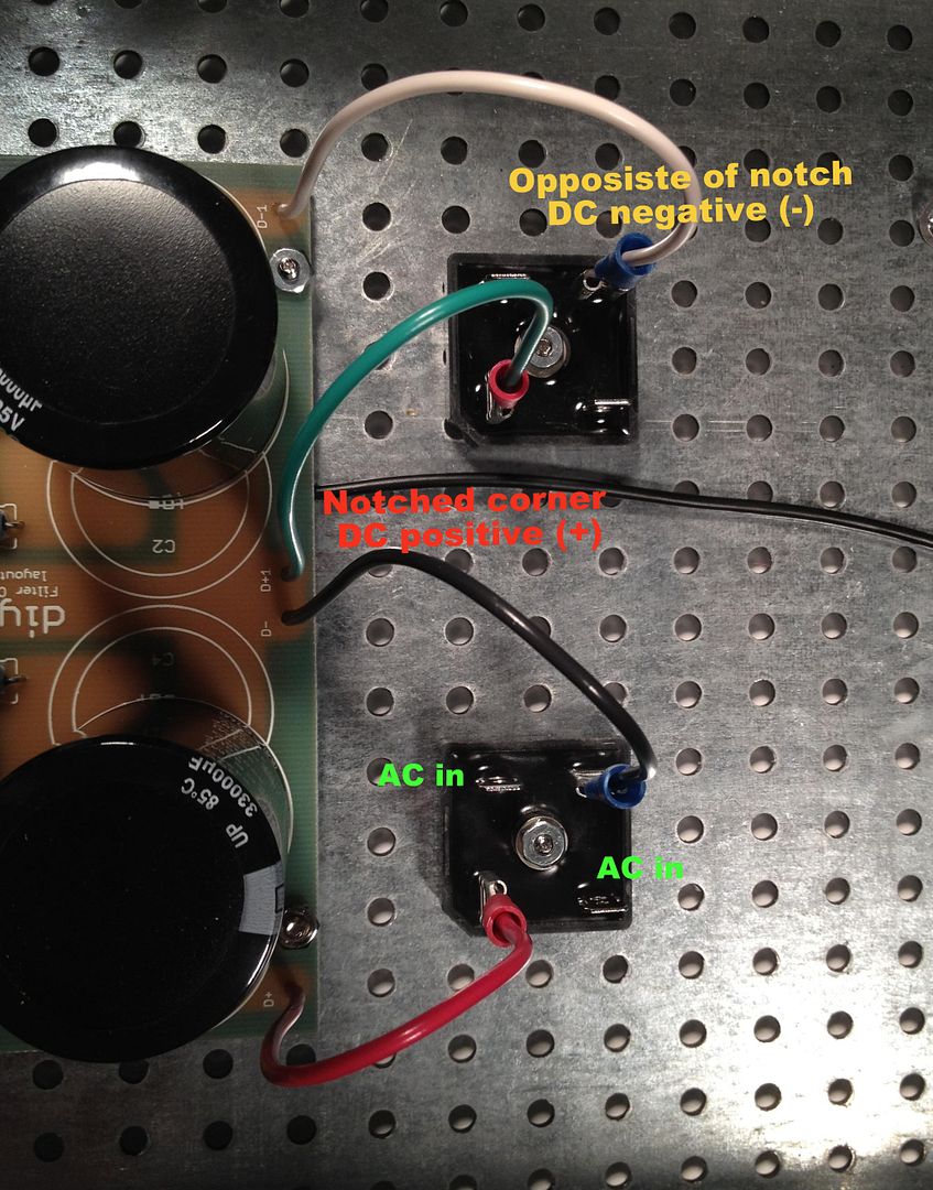
IMG_1502_zps595e76c4.jpg

Here you can see the bridges with the wires attached from the transformer secondary. Remember that the green attached to a bridge must have continuity with the blue attached to the same bridge. (As it's the 2 ends of the same piece of wire)


IMG_1504_zps2330b348.jpg

As long as were are tailing about the transformer, here is a photo of the terminal block shown wired for 120v. The Blur lead is the AC Live, and the clear the AC neutral. The reds and blacks are the transformer primaries.

Transformer is an Antek 400VA 18v+18v, part number AN-4218.

c18876a2-f60a-4a7c-88c1-df7c2333efdb_zps3ff1ace7.jpg


The last bit of the PSU wiring is the chassis connection, the black comes from the PSU GND, and the green is the AC safety earth.

The AC to primary wiring confuses everybody, so;

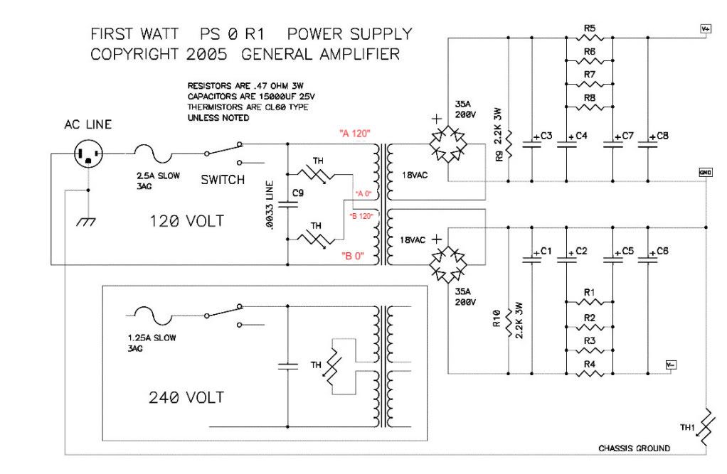
Let's look at the PSU schematic just to make sure everything is OK... Remember that I am wiring it for 120v operation, so the transformer primaries are in parallel. People wiring for 240 with a transformer like this, please ignore.

F5PSUschematic.jpg


Notes in red are mine.

Look at the connections of the transformer primary, through the thermistors and line cap, to the mains.

Hot AC is connected to the "120" (which in my case is the red leads on the primaries) One red primary is connected to AC hot through a thermistor.

Neutral AC is connected to the black "0" leads, one of which is connected to the AC through a thermistor.

AC Hot and Neutral have a cap across the leads.


So, yes, the AC will be connected to the center 2 posts, which is across the cap.

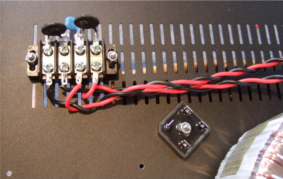
DSCF0098.jpg

(This photo lifted from my F5 thread, but it's the same PSU…)

Left to right we have post 1, 2, 3, 4

POST 1 - Transformer primary 'B 0' which will be connected to AC Neutral at post 2, through the thermistor between post 1 and 2.

POST 2 - AC Neutral in (not shown in photo), connected to Transformer primary 'A 0" , a thermistor to post 1, and a line cap to post 3

POST 3 - AC Hot in, connected to transformer primary "B 120", thermistor to post 4, and line cap to post 2

POST 4 - Transformer primary "A 120", connected to AC Hot through the thermistor to post 3

If you look at the red and black wires in the photo you will see that the Mains AC must to pass through a thermistor to connect to each of the 2 primaries. And that is the point of them, to keep inrush under control during powerup.

Ok!

Now we need to put everything together -

But first a bit more mechanical assembly.

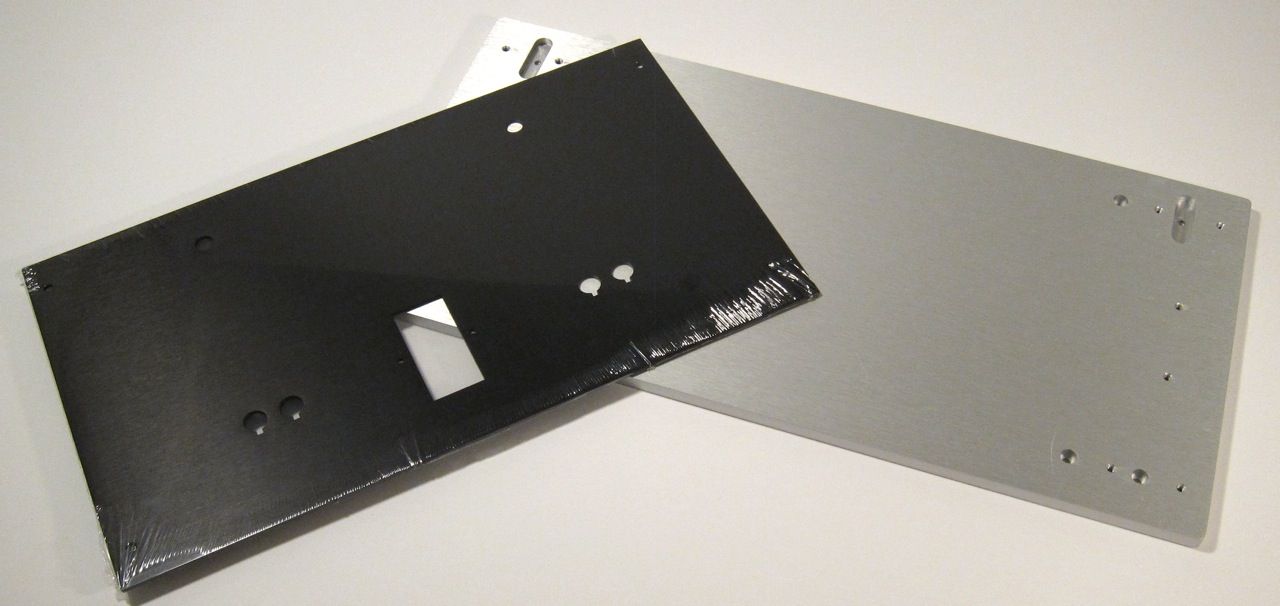
IMG_1318_zps154c4eb4.jpg

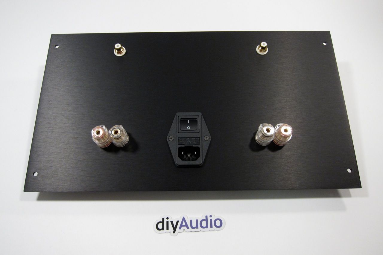
This is the pre-cut back plate and the thick front plate.

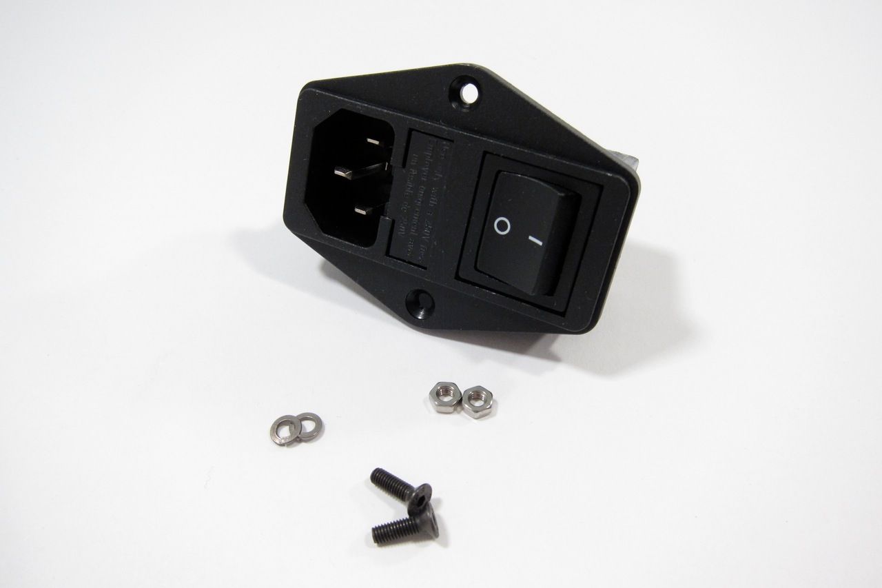
IMG_1373_zps4feae671.jpg

Gather and mount the IEC plug.

IMG_1374_zpsea052fad.jpg


IMG_1375_zpsf81194a0.jpg

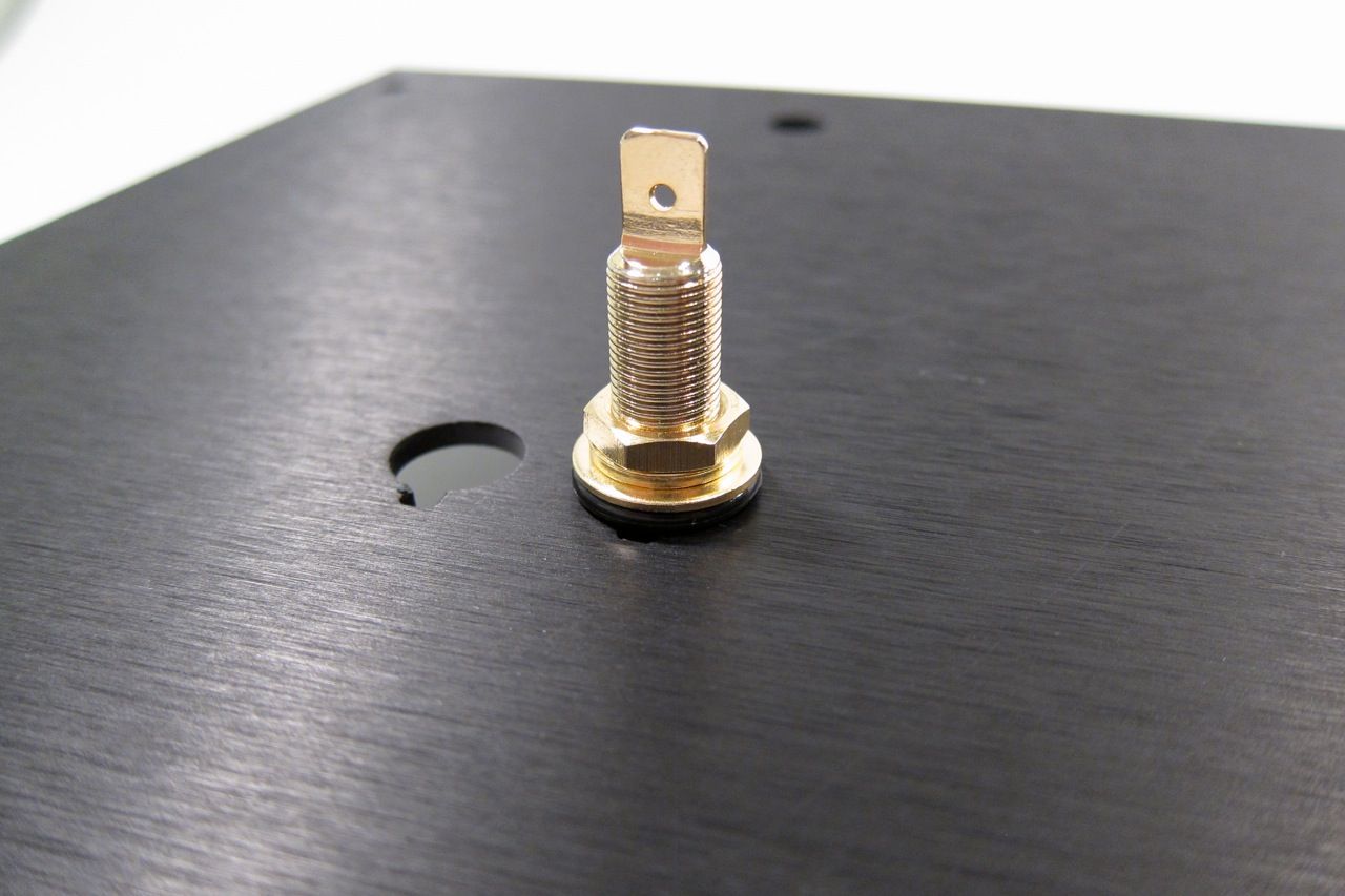
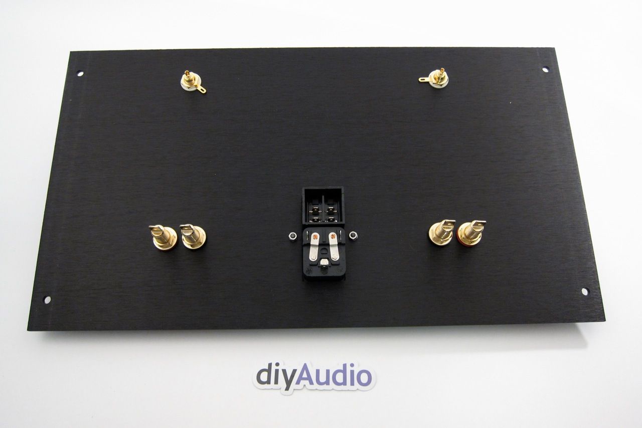
The speaker posts.

IMG_1376_zps78619adc.jpg


IMG_1377_zps52d02da2.jpeg

And the RCA jacks.

Note that the shoulder washer goes on the inside, so the metal of the chassis doesn't touch the metal of the jack. There is a similar washer on the speaker posts.

IMG_1379_zps7ea37734.jpg


IMG_1383_zps81466a6f.jpg

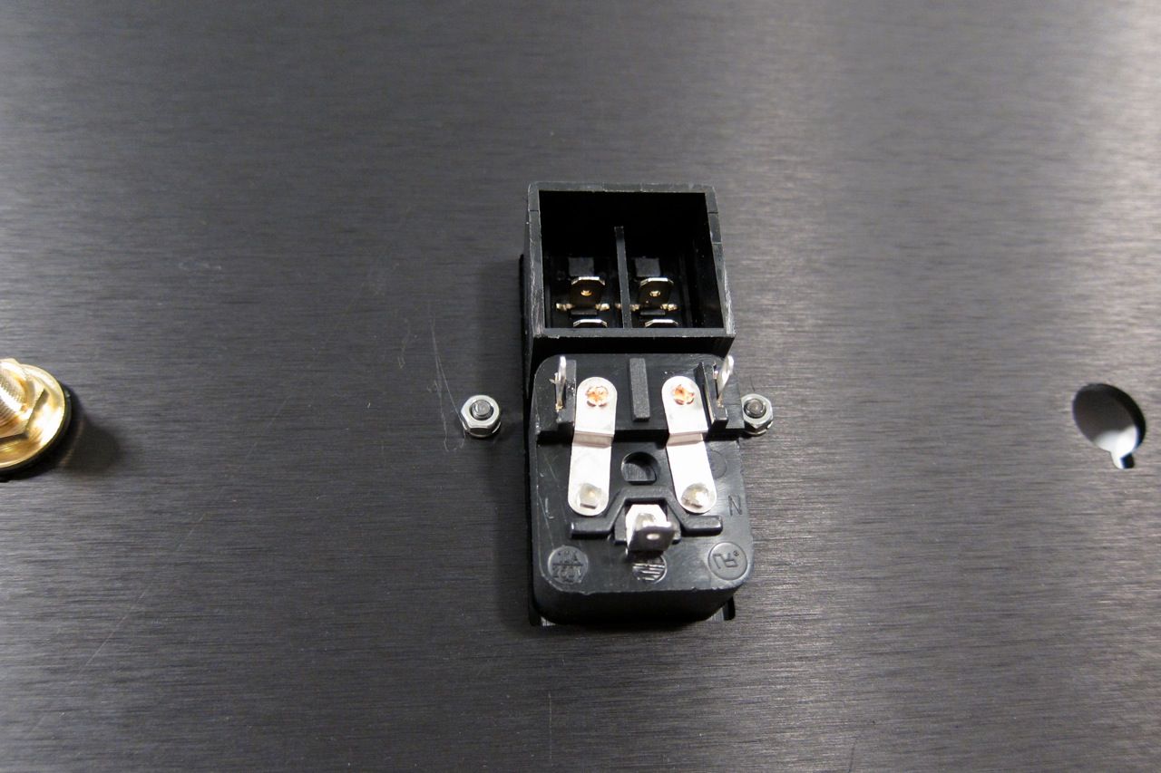
The inside of the back panel.

IMG_1384_zpsa6eac495.jpg

And the outside. Looks good, yes?

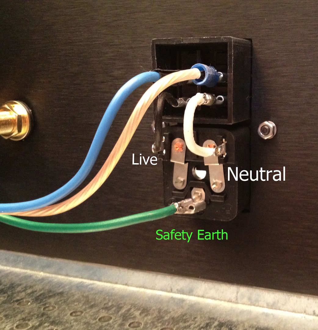
F4IEC_zps6ceffebf.jpg

The IEC module is wired as shown. This will switch both the Live and Neutral. The blue (live) and clear (neutral) go the the wiring block with the thermistors, cap and transformer primaries.

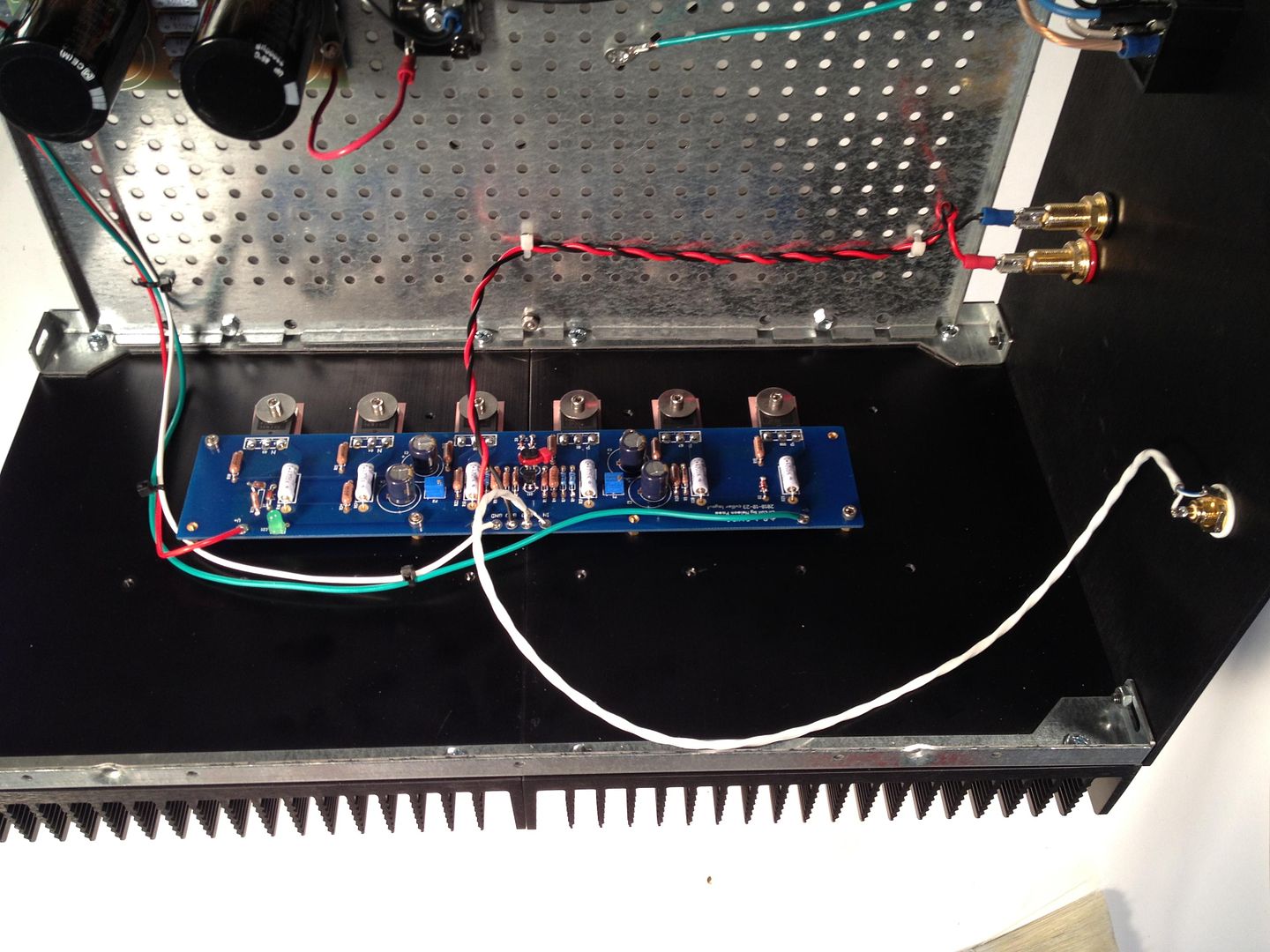
F4_zps1c20d402.jpg

The amp PCB completely wired.

IMG_1500_zpse2fd0def.jpg

A bit closer.

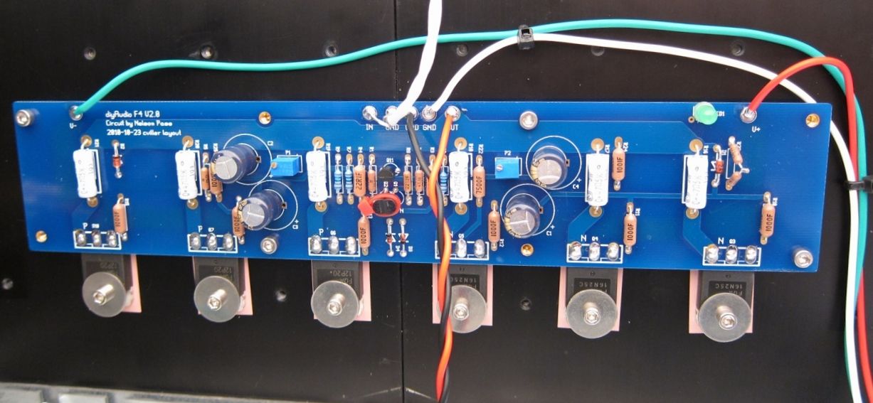
IMG_1508_zps204b9870.jpg

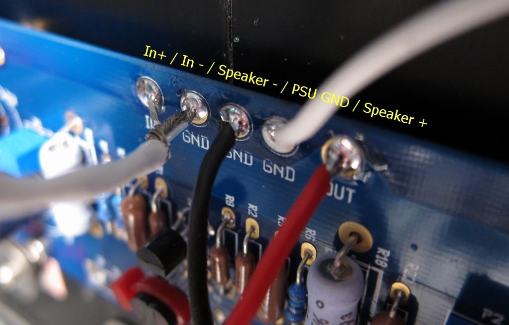
The top connections labeled.

IMG_1501_zps9fc1ace7.jpg

This happens to be the other channel, but the connections are all the same.

Remember that V- / GND / V+ is always left to right as you are looking at the format of the PCB

IMG_1509_zpsf813f64d.jpg

I'm not entirely sure what I was trying to show here, other than the screw and washer. It looks cool. I will keep the photo in the guide.

IMG_1507_zps4cbad30f.jpg


IMG_1515_zps250cb1fc.jpg

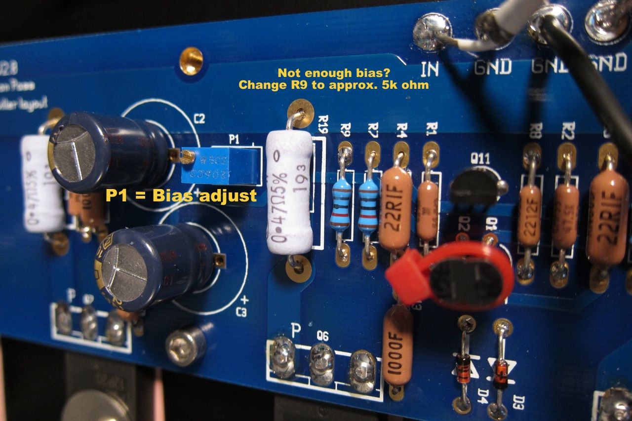
A few notes on bias -
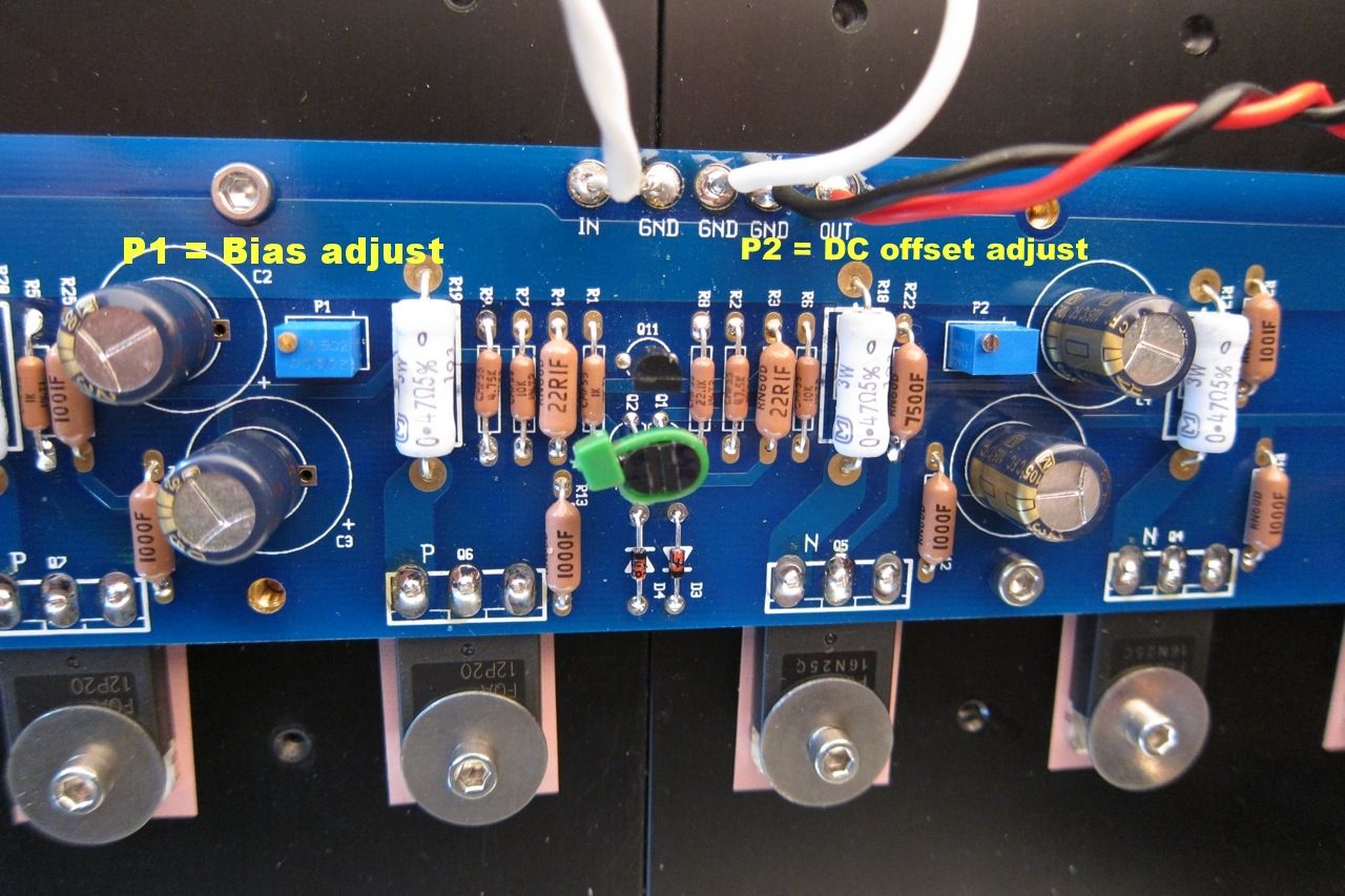
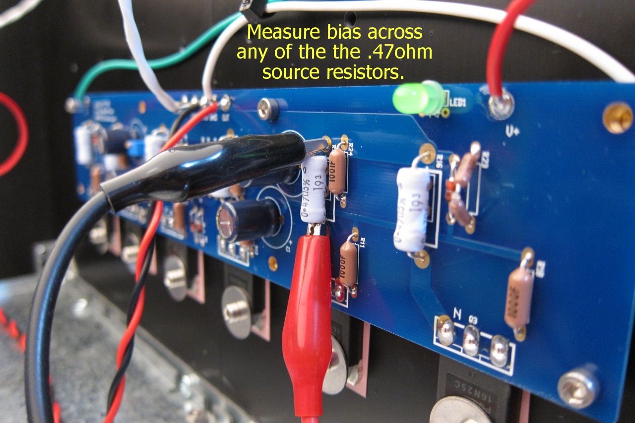
P1 controls the bias, measured across any of the 3W source resistors. Adjust for 0.13v when it's cold, and watch that it doesn't get higher than 0.2v once it's up to temperature in about an hour. Adjust for 0.2v when hot.

P2 is used to adjust the DC offset on the output to zero.

IMG_1517_zpsb9663755.jpg

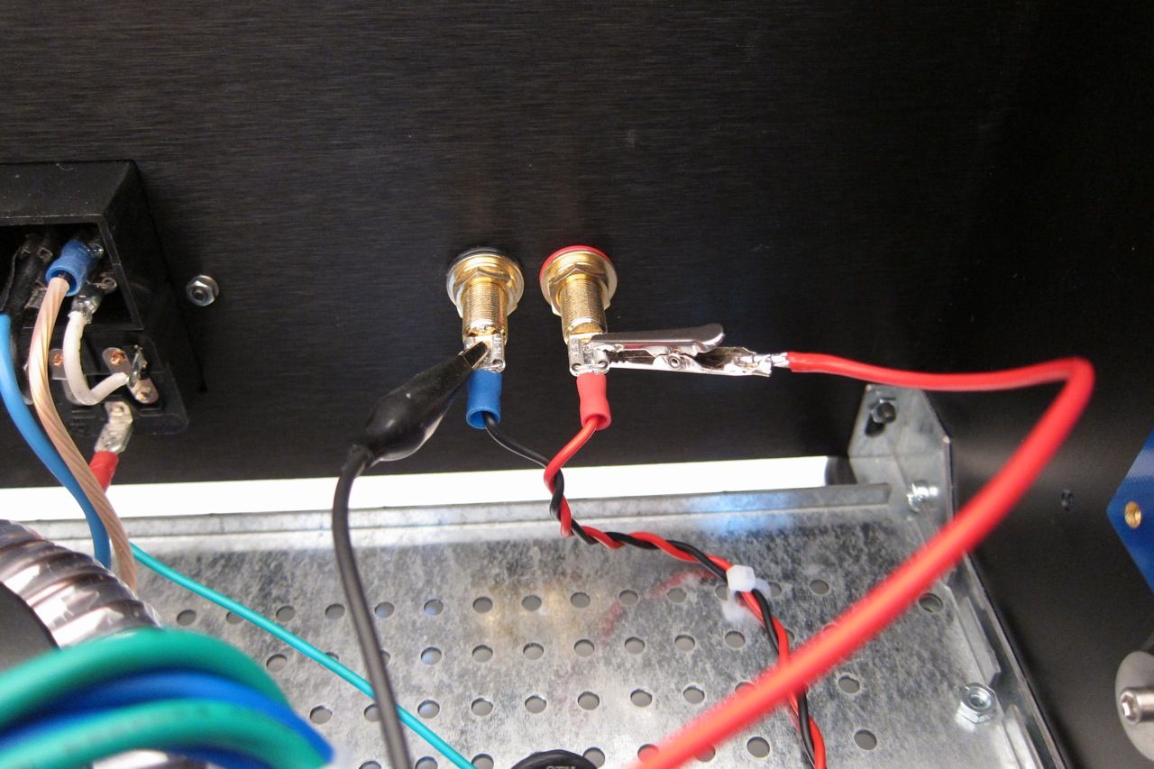
Attach a DC voltmeter across the speaker outputs to measure offset.


IMG_1512_zps4b4f9e14.jpg

If you find that the P1 doesn't have enough range, I.E., you can't turn it up enough, replace R9 with a smaller resistor, I used 4.75K and it works well.


IMG_1513_zps62a0e474.jpg

Connect a voltmeter across any of the source resistors. The outboard ones are easier to clip across.

Adjust for about 0.13v cold, and once the amp is up to operating temperature, trim for 0.20v - It takes a long time to warm up, take your time.

Adjust P2 for zero offset, then re-trim P1

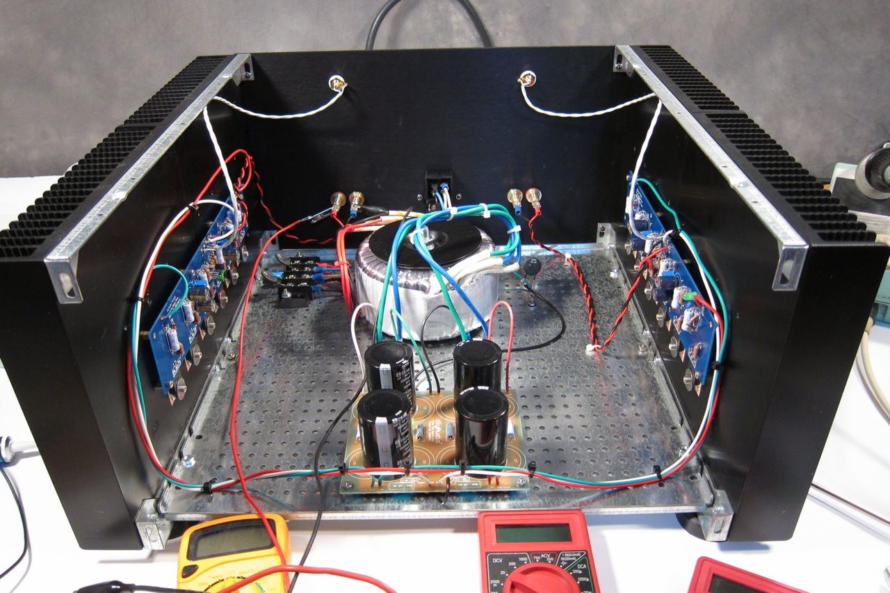
Here is a photo of it all connected and working -

IMG_1506_zpsbb6eed41.jpg


I'm driving the F4 with an O2 Headphone amp sourced from an iPod; Driving 85.5db speakers. Although it is a small room, it gets louder than I want to listen. It still can't drive it to clipping, but it does get really, really loud.

One thing worth mentioning, and it speaks very highly to the quality of the amp, is that it is completely non-fatiguing, and more interestingly, very easy to listen to turned up too loud… I don't realize how loud it actually is sometimes. Complete transparency is a word used a lot when describing this amp - but I have to agree. It's fantastic!


Please comment away if you desire.

Also please feel free to ask any F4 questions here, and if you would like to post photos of your F4 completions, old or new, please do!
The Incredible Technics SP-10 MK3 Thread

In the same vein as 6L6's MK2 thread, I thought we should start one for a related, formidable, Technics beast.

There's not a lot of information out there on these, even if you can read Japanese, or want to try your luck at deciphering Google Translate... Sometimes I think reading Japanese would be easier.

Should any pertinent links or information come up, I'll try to document them in this first post. Skip down to get to the good stuff. 😀

-------------------------------------------------

Mounting Guide for Power transformers, Output transformers and Chokes

I thought it would be a great idea to open a thread on proper ways to mount transformers/chokes/Output transformers.

I cannot find my copy of a great book on the subject.

I was looking for the do / not do of mounting flat chokes on a chassis. I could not find anything on the subject.

1. Rule : never place metal across laminations

XSim 3-way crossover design

I am new to XSim and still learning. This is and all Dayton audio 3-way design with the following speakers.

DC28F-8 tweeter
RS180P-8 ohm paper driver for the midrange
RS180P-4 ohm for the for the woofer. (It looks like the impedance is drop to 3 ohm around 130 Hz.)??

Just a note on my amp. I am using the Outlaw seven channel A/B amp which is rated to 130 watts in 8 ohms and 350 watts into 4 ohm all channels driven.

Enclosure info.

3/4" mdf material
Midrange has it's on sealed compartment
Woofer section 1 Cu/ft. ported to 35 hz.

Can someone take a look at the attached to see if I am on the right track or totally off base. Any recommendations would be appreciated??

Attachments

Making a blind choice...

So I've got a 3 way build about to begin... And my midrange is a JBL 2251 10" mid and the plan was to use what I have on hand... That includes either a pair of Selenium D220ti or Celestion CDX1-1745 drivers and these 2 waveguides/horns:

https://usspeaker.com/dds cfd-1-90pro-1.htm

Or

https://www.parts-express.com/B-52-PHRN-1014-10-x-14-Plastic-Horn-Waveguide-299-2303?quantity=1

I'm guessing I want to keep the width of the waveguide closest to the woofer, and the one has a lower C2C distance. As I've not figured out anything other than my midwoofer and bass woofer, I was curious if there was a set of drivers and waveguides that stood out as the obvious choice to start with.

I am starting active and want to make a passive crossover for the MT section, and will be taking measures etc. Just wondering where the best jumping off point is. Thanks

MEH 2 way + sub vs 3 way

I currently am running a pair of k402MEHs as a 3 way with a pair of f20 subs. I just picked up a Yamaha sp2060 and it offers a 2 way + sub configuration and a 3 way configuration. I like having the full range for my stereo setup (my MEHs will dom20hz to 20k, but I am pushing the M3H 15"Celestion woofers too hard..hence using as a 3 way now).
What is the difference, and what would the advantages and disadvantages be. I am using a Denafrips Athena 2 channel preamp for my stereo setup and feed my Marantz av8805a into one input on the Athena for movies.

Any experience with BTM383 (QCC3083-based Bluetooth module)?

This is the module:
https://www.tianjiarun.com/post/125.html?language=2
My aim is to have a BT receiver that supports "advanced" codecs and that can output a I2S stream.
The QCC3083 is not directly available to consumers.
This module seems a reasonable solution (~ €10 on aliexpress), but the documentation is just an enumeration of pins...

Frank's 6SN7 preamp output capacitor question

Hello. I'm simulating Frank's 6sn7 preamp and have a question about output 5uf capacitor. If I leave it with 5uf than the operation will stabilize around 30 sec (please consider red and purple waves in the plot) . If I use 0.047uf instead the amplifier will work from start. What's the use of such capacity?

Attachments

  • IMG-20250323-WA0001.jpg
    IMG-20250323-WA0001.jpg
    36.7 KB · Views: 137
  • изображение.png
    изображение.png
    36.2 KB · Views: 132

DC 2A3 SET Low Freq Rolloff

I built the attached amplifier circuit using OPT’s with the specs indicated in the 2nd attachment, I paid pretty good money for these. My system is located in my small office which is 11’ x 12’ x 8’. Finally got around to running test-tones and saw that I’m not getting anything below 50hz and the low end starts rolling off at 100hz with my speakers. I can fill in the bottom end with my subwoofer. Just for grins I hooked up my mobile amp, a little Dayton T-amp which cost me all of $35. Without my subwoofer the low end is not missing with this little amp. Can anyone point me in the right direction on what could be causing the low end rolloff with my 2A3 amp?

Attachments

  • 84ED0325-6520-45D0-9D1C-D2F31C8F7C72.jpeg
    84ED0325-6520-45D0-9D1C-D2F31C8F7C72.jpeg
    163.5 KB · Views: 242
  • AE70B1ED-6B06-4C98-8051-B5C550DAE644.jpeg
    AE70B1ED-6B06-4C98-8051-B5C550DAE644.jpeg
    178.4 KB · Views: 239

Open baffle with Mid Bass 15pr400. One or two? For that extra 3dB to match my Mid Horn BMS 4592

Well not match but to be closer to the mid. Since the Volti Vittora is 105dB efficient with the bass horn. I thought integrating the mid bass with the mid would be somehow better with mid bass being 103dB instead of 100dB.

Situation:

Listening area is 45m2 (floorarea)

I'm planning an open baffle mid bass with 15pr400 (Got it years ago for a good price so not looking at any other drivers) (120Hz-500Hz)

Bass will be done with a closed sub I already have with BMS 18n850.

Bass and Sub Bass will be powered and 'crossovered' with miniDSP PWR-ICE250. ( <120Hz) one per side so. 4 channels total) So I'm assuming at the levels I play the amp can handle the 4 Ohm mid bass easily. (should I choose to go 2 mid bass per channel)

Mid 500Hz-6kHz=BMS 4592 mid on JBL 2380a clones.
High 6kHz =faitalpro 10hfak on sth100.

Crossover will use Crites 3636 to bring the mid and hf levels down. So mid and high with SE tube amps and as you can see a passive crossover.
Mid Bass open baffle because I baulk at building a box with current prices of birch ply and my poor woodworking skills. And Troels raves about the bass on his OBL15.

Question: should I got for an extra pair of 8 Ohm 15pr400 paralleled for an extra 3dB? Would be another 600 euro ex shipping. So what would that extra 3dB bring to the whole setup? In terms of subjective added value.

This is an end game speaker for me.

Calculating speaker cabinet volume

For calculating internal cabinet volumes, how do you factor in cabinet fillers? For solid rubber matting or something dense like XPS foam, it seems reasonable to just subtract the volume used from the total volume. But what about polyfill or denim matting? Maybe for each cubic foot of polyfil, subtract something like 0.5 cf? Then a little more for denim, like -0.6 or -0.7? Some of the air in the polyfill has to contribute to the overall volume, right? Thanks for the help in advance! -Tony
Ricci's Skhorn Subwoofer

Well here's some info on my newest project. (Skhorn is pronounced like the word scorn.)

In short this's something I've been working on for years to replace my Othorn cabs. The design goals going in were pretty much the same. PA or very high level music playback in large or outdoor spaces. The main areas that I wanted to improve over the Othorn are as below.

#1 Cut down on cabinet and panel vibration near the driver.
#2 Improve the fold or reduce build complexity.
#3 Higher overall performance.
#4 More driver options and some less expensive ones.
#5 Increase the “FUN” factor even further

After simulations of what seemed like every cab type and most of the commonly available drivers, I ended up ditching the 8th order BP I had, which looked really good on paper, but was an absolute nightmare to turn from a sim into a buildable cab. Not to mention the extreme sensitivity to mistuning, etc... After that a TH was going to be the follow up and I had it all drawn up but I just wasn't satisfied with it as it seemed like an incremental step rather than something new. Finally I settled on the cab type also used on the M.A.U.L.. It was basically a parallel effort on both designs. The big one just happened to get built and tested first.

The Skhorn is a 24x32x54" cab that is comparable in size to the low tuned dual 18 vented cabs on the market. It's 24cu ft or 680L external volume. Originally I wanted to keep the size the same as the Othorn which is 18cu ft external but using 2 large drivers simply required a bit more volume and a different shape. The Skhorn is exactly 33.33% bigger than the Othorn, so 3 Skhorn are the same volume of space as 4 Othorn cabs.

I settled on a quasi 6th order BP, where the low end is vented and the upper end of the loading is a short, expanding slot/horn, with an opposed pair of 15-21" drivers, in an OD arrangement. I ended up at this while trying to work on translating a standard 6th order sim into wood and screws. I was having trouble getting the upper bass vents to fit into the cabinet and this caused me to look at how a straight slot performed instead since it is MUCH simpler to fit into the cab design. From there it was natural to model the slot with both a positive and negative taper and see what happened. A positive flare seemed to offer some improvements over a simple vent and with tweaking of the length, area and expansion, I found that this type of loading for the drivers could produce a smooth response over a wide bandwidth while also exhibiting some gains over a standard vented system using the same driver.

EDIT: 02/20/18
I have improved the accuracy of HR simulation inputs when compared to the measured ground-plane performance of the final speaker. The HR inputs below are not nearly as accurate as those developed after testing the final cab.


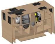
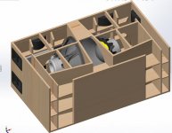
Here’s the cab design.
SKHORN ISO 2.jpg
SKHORN ISO TOP REMOVED.jpg
SKHORN ISO FRONT REMOVED.jpg
SKHORN ISO HATCHES.jpg
SKHORN ISO.jpg

Attachments

  • SKHORN B&C 18RBX100.png
    SKHORN B&C 18RBX100.png
    54.2 KB · Views: 2,003
  • SKHORN Faital 18XL1600.png
    SKHORN Faital 18XL1600.png
    29.4 KB · Views: 1,910
  • SKHORN 21SW152-4.png
    SKHORN 21SW152-4.png
    47 KB · Views: 1,935

FOSI LC30 improvements

Hi *,
I bought the LC30 two weeks ago. In my eyes mechanical and optical a very well done device but for me it has two issues:

  1. It does not self power on if 5V comes up via USB. Would like to see a jumper inside where this could be configured.
  2. The display is uncalibrated. Nearly no movement at low levels and the meter swings much too fast.

I decided to develop an add on prototype PCB which I mounted into the box. There is much space inside so my additional prototype PCB nicely fits in there. It uses two AD8310 devices (used it as I never worked with it before and was curious) to create a real logarithmic output. Also I added some other components to be able to exactly calibrate the meters.

As I‘m not able to solder the tiny AD8310 I bought two of these PCBs, and mounted them on top of my breadboard. I had to modify them a bit to work with audio frequencies but this was quite straight forward.

With two potentiometers I’m now able to calibrate the 0dB and the -40dB levels at 1000Hz. After calibration the levels in between also fit. Only drawback is that the scale of the meters above 0dB is not logarithmic. So the values shown above 0dB are wrong. A damping resistor across the meter establishes critical damping so I get only a very small overshoot from pulses.
I‘m very happy now with this solution 🙂

I also integrated a NE555 and a small DIL Relais that simulates pressing the power button after 5V from USB comes up.

If someone is interested I offer to draw the schematics and publish it here. I also made some fotos during my work that I’m also willing to share. Maybe someone with skills in PCB layouting and producing will kick in and build a circuit board equipped with components so others also can upgrade their unit.

I uploaded the schematics and Fotos of my implementation in the Audiosciencereview thread of the LC30. Please follow the link for more information...
https://audiosciencereview.com/foru...speaker-amp-switcher-meter.57415/post-2270108

Best DrCWO

New to this forum, I'm from Sweden.

Hello guys.
Im from Sweden and i saw an older post of someone seraching for the "Audio Generator GAG-808D", and i have one at home if he still is interested, i especially created a account to reach out to him.

So i hope to get help to reach out to him, i tried to reply to his older post but i somehow wasnt allowed to post since i havnt "reach enough credit points" or something?

Hope you guys can help me/him out.

Cheers!
Attachments

  • 55.jpg
    55.jpg
    290.6 KB · Views: 23

Support boards for new Wolverine AMP (PSU, SSR, Ground Lift, Bal Input)

Since I'm plugged into the latest GB on the Wolverine amp, I'll be putting in a production pcb from the list below...

PSU Board (2oz blue)
power_supply_2pin_diodes_big_pcb_top.jpg power_supply_2pin_diodes_big_schematic.png

Small heatsinks SK 75 37,5 STS - price on request
sk75 37,5.png

MBR40250G - When ordering 100 pcs, the price on the mouser is already acceptable 😉

SSR protect (2oz blue)

HRDSTL-SPK-PROTECT-STUFF-400WBIG-DC.png HRDSTL-SPK-PROTECT-SCH-400WBIG-DC.png

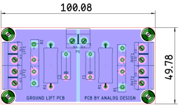
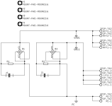
Dual Ground Lift (2oz blue)
GND LIFT LAY.png GND LIFT SCH.png
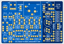
Bal/Unbal input
bal_unbal input.png
Support psu for bal/unbal input

...in proggress

If anyone would like, just write me a private message. The deadline will be 4.5.2025 and the boards will be ordered.

New pre-amp: B405 with BH rectifier

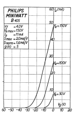
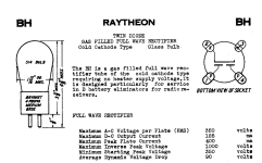
Hi everyone, hope all is well. This is the latest design that I came up with for a Low mu pre-amp with autoformer. Very simple design with a quiet power supply. The pre-amp is intended to drive a 10K impedance. Input will be a 2Vrms digital streamer. I can't find much user experience on the BH rectifier, other than the spec sheet (attached). Would like your thoughts on this design.

Attachments

  • “2024-02-22 15.png
    “2024-02-22 15.png
    176.4 KB · Views: 342
  • “2024-02-22 11.png
    “2024-02-22 11.png
    430 KB · Views: 324
  • “2024-02-22 5.png
    “2024-02-22 5.png
    403.1 KB · Views: 328

Novatron/Cocktail Audio X30

Hopefully this is in the right area.

I have a Cocktail Audio X30 that doesn’t want to power up fully.

When the power button on the front is pressed, the LED briefly flickers green and the relay can be heard to click, but then it instantly powers down.

I had hoped that it was just a fault with the relay, it’s a Handouk HE-1A-DC, but when I have removed it and tested it it seems to operate as intended.

Does anyone have any experience with these?

Any help and all suggestions appreciated.

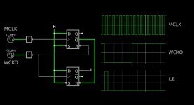
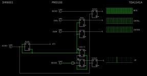
PMD100 to TDA1541 in smultaneous mode

Hi,

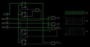
continuing from this thread I would like to open a new thread about interfacing a TDA1541 based DAC to a PMD100 based frontend, but the information about this topic seems to be lost. Here are the links I found:
I also found some information on hifidiy:
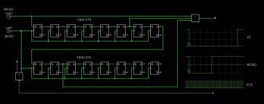
I simulated the mentioned circuits:
Attached screen shots of the simulations where the timing of the created LE signal is shown.

EDIT: simulation of PMD100 glue logic for stand alone mode. Post #102 gives a summary of the reclocked glue logic circuit I installed into my Arcam Delta Black Box v.1, post #228 contains the final simulation, #229 the latest mcu code to configure the PMD100 in programmed mode and the latest schematics, #230 shows the final state of my Arcam.

Attachments

  • gluelogic Nakamichi timing.jpg
    gluelogic Nakamichi timing.jpg
    95.5 KB · Views: 439
  • gluelogic SM5813 timing.jpg
    gluelogic SM5813 timing.jpg
    110.1 KB · Views: 426
  • gluelogic PMD100 timing.jpg
    gluelogic PMD100 timing.jpg
    52.2 KB · Views: 492
  • gluelogic PMD100 stand alone.jpg
    gluelogic PMD100 stand alone.jpg
    112.6 KB · Views: 220

Cambridge Audio Azur 840a Int amp - broken toggle switch - cannot find it in the schematics!

Hello all - I hope your projects are going well.

Today I got a CA Azur 840a for a very reasonable price. The seller claimed input one was dead on both the RCA's and XLR's. Reading up on this amp - I discovered the inputs are controlled by relays - and my suspicion was that the input one relay had gotten sticky. Not so - I can hear it activate robustly. Turns out the wee toggle switch on the rear panel that selects either the RCA or XLR inputs has been broken and is flopping about.

I found the service manual and I cannot, for the life of me, find mention of this switch anywhere in it.

In my initial listening - I like the sound of this amp - and I'd like to get it working completely. All the other inputs operate fine.

I'm happy to either replace the switch - but would love to discover the part # so I can order it before taking the amp apart - or simply rewire the circuit so that input one is hardwired to the XLR inputs. I don't often sell gear and this will likely stay in my collection for a good while. So getting it back to factory spec isn't important to me.

But I can't discover in the schematics or the BOM what's needed for either approach.

Any tips?

Link to the service manual is here: https://elektrotanya.com/cambridge-audio_azur-840a_ver.2_sm.pdf/download.html

Thanks in advance!
RK

Simple DSD modulator for DSC2

It's nice to present this project - separate delta sigma modulator for a dsc2 dac.
Special thanks to Jussi and Pavel.

The basic idea is to convert pcm to a dsd stream without the use of a PC.

Design flow goes as follows:

i2s serial data is converted to parallel, next we have the first interpolation fir filter,
in this filter the data is oversampled x2, x4 or x8 - this depends on the incoming data rate.
(for 44.1kHz we have x8 interpolation, for 96kHz x4 and for 192kHz x2)

next, the data is going to the two stage CIC filter and is oversampled x32 to final x256

Then the data is going into the sigma delta 7 order modulator, which has classical CRFB structure,
as I said earlier all arithmetics are done in CSD arith, so no multipliers here.
all coefficients are carefully optimized using delsig package
If someone asks, yes, there are g0, g1, g2 coeffs.

At the end the dsd streams are time aligned using ODDR2 primitives

XC6SLX9 is almost full, so there is no ability to add anything 🙂

The device was designed to run with a mclk of 22/24 MHz.

To upload the attached bitstream file to the board you need a Xilinx programmer cable and Xilinx program Impact.

In the next post my friend PJotr will post gerber files, BOM and some measurements.

I hope this project will be interesting for someone.

DIY use only!

--------------------------------------------------------------------------------------------------------------------------------------------------------
Update 24.07.2023 New firmware !

First of all, I'd like to thank Markw4 for your help!

The entire software is practically completely new.

The first FIR filter now has x8 fixed interpolation (fs 44.1kHz - 192kHz), has 2048 taps, 32 bit coefficients and 100dB stopband attenuation.
Then it's a two-stage CIC filter and it's oversampled to the final x256. Oversampling depends on the rate of incoming data.
Then we have a 5-order sigma delta modulator, which has classical CRFB structure, with noise shaping and dithering.
And as before, at the end the dsd streams are time aligned using ODDR2 primitives.

We made tens of different firmware configurations and finally chose this version after listening sessions.

Latest firmware:
https://www.diyaudio.com/community/threads/simple-dsd-modulator-for-dsc2.370177/page-42#post-7407495

Attachments

  • DSC02017.JPG
    DSC02017.JPG
    580.2 KB · Views: 2,578
  • DSC02027.JPG
    DSC02027.JPG
    591.2 KB · Views: 2,513
  • top.zip
    top.zip
    45.5 KB · Views: 810
  • Like
  • Thank You
Reactions: iperv and olsond3

Classe CA-401 Rebuild

I'm rebuilding a Classe CA-401 after one channel blew out. I'm documenting the entire experience to keep track of everything I've done and to help out others. Enjoy!

Every power transistor in the channel was blown. Here's a picture of the vaporization leftovers of the 10N20 and 10P20 gate resistors. Also, check out the 383R VBE multiplier resistor residue in the top right corner:

classe-ca-401.jpg

Pentode output modes

I am a relatively new tube amp DIYer. Built two spud amps, a 6BM8, and a 6LU8.

Now, I'd like to try a single ended EL84. I understand that there are at least three output modes, pentode, triode strapped, and ultralinear. I haveno interest in triode mode.

My understanding is that pentode mode would have highest power, and highest distortion. That is mitigated through global negative feedback which reduces distortion, but also decreases output. Ultralinear, reduces distortion,likely better than gnf, but doesn't it also reduce output power?

My goal is to drive the el84s to getthe highest listenable output, basically, headroom. I normallylistento my 6lu8 at a modest volume, and likely similar volume for the el84s. My quest would be not to have the lowest distortion at max output, but low(ish) distortion at listening level, butwiththe mostheadroom I can get.

Now, I know gnf is typically defined in dB negative feedback, but I do not have the knowledge to understand the relative significance of say 15db at a 3 watt output. Especially compared to say any power sacrifice going UL.

There are ma y schematics outthere using both either UL. or gnf.

Help me understand the benefits of each approach.

Tia,
Roger

NAD C326BEE keeps turning on

Hi all,
my NAD c326bee has serious problem. It keeps turning on and the buttons on front of the panel are irresponsive and also the standby button. The only mode to turn the amp off is to use the hardware switch on the back panel. When the amp is in this state (power on but irresponsive), it becomes quite hot. The problem was fixed in april with a quite expensive repair, now the problem returns.
Is there a way to fix this weird malfunction?

Thanks

New at DIY Audio World

Hello all,

My name is Neeraj, I am from Maharashtra, India. I am 38, but new to the world of DIY Audio and am not from a technical background (I was a commerce student) but I am very much interested in audio.
Some years back, when I came to know that the expensive audio equipments can be made at home, I started studying from the very very basics of electronics and started learning etiching pcb at home.

Till now I have eatched PCBs and assembled Amp Boards like couple of designs for TDA7294, Couple for designes for TDA2009, TDA2030. Some transistor amps based on the design of Sir Marshell Leach, Honey badger Amp, Apex A14 Amp. Also OM2.7, OM3 and ISOTOP from Russian website. Some preamps like P20, P30, P4 etc, some Subwoofer filters including sub filter from Mr. Mile, also eatched some soft start, Protection pcbs, power supply pcb, selector pcb etc etc... All are working.
Using some of the above PCBs, I assembled some Stereo Amps and some 2.1 amps using DIY pcbs and Old Dead AVReceiver cabinets (bought from scrap) . All are working without any major issue and with regular improvements.

There were some failed projects too. some noisey preamps were there, some amp designs were there like Jat501, Apex SR150, Apex SR100 etc etc etc.
I have Zero knowledge of PCB designing as of now, hence I need to rely on PCBs designed by the experts. But I will start learning it soon. My failure to success ratio is 1:1 as of now will try to improve it.

After 4 to 5 years, One thing I understood very well that "DIY IS NOT CHEAP". You will always end up spending more on DIY then on a professionally made commercially available similar powered AMP purchased. Also there are some issues like getting good quality (Original) componants at an appropriate price. I have seen vendors selling componants at 3 times 4 times the actual price. And the most important part is DIY have its limitations, It is not imposible to DIY Good Quality DAC, Preamp, Digital selector etc etc but the cost to do that all will be hudge. But, for me, I am not in a stage where I can turn back, hence I will continue doing it and will try focusing on Class AB Power Amps Only.

Since I have read about Apex A40 Amp a lot and every body was loving the quality of sound it produces, I also tried to assemble it. But kid of failed as for now and trying to find a solution on the forom.

Creating my own audio analyser

Hello, my name is João, and I’ve been working with a few friends to develop an audio analyser called beHydra (feel free to check it out here: https://beembedded.com/behydra/).

I joined diyAudio to learn and understand everyone’s needs when developing audio related products, which is why I’m developing the audio analyser myself, given what’s in the market is a bit expensive and not necessarily developer friendly. Happy to discuss what I've been working on 🙂

Looking forward to exchanging ideas and learning from everyone here!

For Sale Large lot of EL34, 5881, 6L6, 6550, KT88, KT90, 7591 tube, All tested

Hi there,

Up for sale is a large lot of power tubes, all in the octal family of EL34 / KT88 / 6550 / KT90 / 5881 / 6L6 and 7591.
All details can be found in the file attached to this post. All good and tested in my calibrated TV7-D/U. You can find the actual reading and the "good" threshold for comparison, plus a lot more information on condition, origin, etc. And if there's anything else you are missing, just ask.

Price for the entire lot (54 tubes): 650 EUR / 700 USD. Shipping (priority and registered) should be between 25 EUR (Europe) to 50 EUR (America / Asia).
Payment by bank transfer or Paypal F&F.

I am also open to reasonable offers, either for the whole lot, or for significant parts of it. Offers for smaller lots are also welcome, but please understand that I need to prioritize the bigger ones. I will try to reply swiftly to any offer or question.

After one month from this post, I will start offering whatever is left in individual lots, but prices will have to reflect the unavoidable overhead of smaller transactions.

Thank you!
Ignacio

Attachments

  • Like
Reactions: ceylon.mooney

Hiraga Le Monstre 2024

Amazingly, 40 years on, one can still find plenty of DIY examples on the internet.
It has been on the to-do list for long.
And finally we got round to it ourselves, with 4 different version.
https://www.diyaudio.com/community/threads/hiraga-le-monstre.5462/post-7622181


240524 Le Monstre Deluxe Proto #1.JPG


Patrick

.

Attachments

I have been researching and designing circuits for High quality home Stereo system. My main sources have been THAT Design notes and Douglas Self books

that ha r1-SCH.png
HI everyone.
I have spent some time designing my system and have now almost completed the preamp design. I am at the moment looking into a headphone output, and hence looking at various circuits around the bazaars. I came across a simple circuity using THAT 1646 balanced driver amps that looked promising but I am confused as to why the input is connected to the amp sense terminals rather than pin 4 of the amp. Hoping someone can explain why this has been done. I have attached the circuit here for reference

Why is this edge connector so hard for me to find?

After 2 days of scouring Mouser, Digikey, image files, and various manufacturers, I can't find replacements for this 2mm pitch, 11 position, square pin receptacle/connector that include the PCB stabilizing clips at the ends. I've tried multiple keyword variations, and all I can find are right angle receptacles without the clips. I'm redesigning some burned circuit boards for a rare Audire amplifier, and would definitely prefer to replace this with the same configuration if it's even possible.

Any help much appreciated - thanks!

2mm Edge connector top.jpg

2mm Edge connector bottom.jpg

Hello

My name is Prezmo and I live in Poland.
In my free time, I do audio electronics as a hobby.
I came across this forum looking for information on improving the JLH1969 headphone amplifier.
I got my hands on a ready-made Gzlozone board, but the sound doesn't satisfy me. I'm looking for solutions to improve it.

Dipole speaker mimicing

Hi. Thanks for reading. After listening to a pair of dipole speakers I am impressed by the spaciousness of the sound. Two drive units connected out of phase with each other, which destroys the direct sound reaching the listener’s ear, so the listener only hears the reflected sound from the room’s walls, causing a spacious kind of sound.

But it seems to be an expensive build, with more drive units required. Is it possible to mimic dipole speakers with a non-dipole speaker, by using the out of phase back radiation in some way. I tried it by removing the back of the speaker enclosure, hoping the read radiation would destroy the direct sound, but it did not work well, the dipole speakers sounded much more spacious

DIY Dynamic Decompression of Music Tracks

I've been using Fabfilter Pro-MB for some time now to reverse some of the effects of music track dynamic compression during mastering...but not mixing, of course. I've found some interesting tidbits of information while using it:

1) Dynamic expansion with a good multiband upwards expander (like Pro-MB) is possible if the dynamics of the music track haven't been completely crushed into oblivion. In DR Database terms, this means that if the music track has at least a 6-8 dB rating using the "TT Dynamic Range Meter" (the standalone version or as a plugin for foobar2000), you have a reasonable chance of a good listenable outcome using multiband expansion. The maximum DR ratings that can benefit from expansion seem to be around 13-14 (dB-crest factor) on the DR Database scale. Any tracks compressed to lower dynamic range values seem to be "lost causes". It's much more productive to go on a hunt for a higher dynamic range version of the recording rather than trying to use a multiband expander.

2) The plugin settings used to expand tracks are usually most successful in increasing dynamic range in the higher frequencies of a track than the lower frequencies below ~100-200 Hz. This means that the crest factor ratings of the tracks from the TT DR Meter may not change very much (due to the fact that crest factor is really measuring bass dynamic range, but not really higher frequency DR), but the tracks themselves will present a much more crisp and forward sound quality for dynamic transients--like ride cymbals, crash cymbals, bells/cowbells, glockenspiel, all handheld percussion instruments (particularly latin instruments), string attack transients, marimba/vibe strikes, drums, and human voice transients.

3) The "steeliness" of string orchestras used in lush pop string arrangements and mass string orchestral scores (classical) will largely be suppressed if using the multiband expander carefully. This was a big surprise.

4) Any human voices, particularly female voices, will begin to sound much more realistic and without typical harshness that comes with listening to recordings having compression applied during mastering. This was the biggest surprise of all in my explorations using the expander.

5) The albums that respond most strongly and easily to multiband expansion seem to include those that had analog compressors applied during mastering (e.g., early-late 1970s albums), which apparently used continuously varying nonlinear compression curves without a sharp knee breakpoint/thresholding applied during mastering.

6) The music genres that seem to respond most strongly are funk, rock, folk, jazz (including smooth jazz), progressive rock with lots of drums/percussion, dance, and related genres. Those genres that seem to respond with more difficulty include smoother music genres having lots of midrange energy (i.e., ambient, new age, classical string orchestras, classical guitar, etc.).

7) All tracks that have used multiband expansion need to be adjusted before and after expansion using parametric EQ demastering.

__________________________________________________________________________________________________________________________

It's clear to me that the use of a multiband dynamic range expander is now standard equipment for my typical demastering tasks that I perform on most of my incoming discs.

I don't recommend trying to do expansion "on the fly" (without review and adjustment of expander settings track by track) unless extremely mild expander settings are used, which leads to barely audible subjective differences in the compressed tracks. Using an expander offline and taking a little time to get the setting right to get the best and most audible results is my strong suggestion in using these type of plugins. However, the task only has to be done once for the music tracks--then saved for future listening, instead of having to set up a custom string of plugins and parametric EQ settings each time a music track is played.

(My original text above was originally posted to another audio forum, albeit an unstable one, and has been moved to this forum to ensure its longevity.)


Chris
Projects by fanatics, for fanatics
Get answers and advice for everyone wanting to learn the art of audio.
Join the Community
507,798
Members
7,888,848
Messages

Filter

Forum Statistics

Threads
406,261
Messages
7,888,848
Members
507,798
Latest member
Mrookster