Power supply fet question

I got an amp in to check over to make sure everything is ok with it before installing .

The amp is using IRFP3206 as the power supply fets with A1275,C3228 as the drivers .

There are a total of 6 banks of power supply fets in this amp each bank has its own drivers .

I noticed the power supply fets are not all the same date code in 1 bank they have one date code and another bank has a completely different date code . This amp has never been worked on before .

So my question is is this ok to run the amp like this or should all the fets have the same date code and be from the same lot ? There are 3 different date codes

The owner said he didn’t mind if they need to be switched out

PAM 8403 with Bluetooth - First Impressions

The PAM 8403 that I ordered from Ali Express arrived yesterday. Just hooked it up with my Diamond IV for testing. What a nice surprise!

A really serious amplifier, plays loud at 72 dB at 1 metre without distortion, and good bass. No trace of class D metallica. There is that slight mid to high range emptiness, but this was swiftly corrected with a equalizer setting, and this is Bluetooth 4 after all, from my HTC explorer legacy device.

My previous 8403 burned out when I shorted out the speakers terminals I think, so must be careful. A great reference amp. Really nice.

1679204249729.png

Tachi - Coaxial Point Source BEM modelling

A post from kimmosto on ASR got me thinking about vertical directivity. I am now more convinced that the reason I like my line array more over a wider range of music than any other speakers I have tried is due to the vertical directivity response.

https://www.audiosciencereview.com/forum/index.php?threads/some-help-with-lobing.22661/post-755427

I've done huge vertical directivity, so the last option on the list a coaxial mid tweeter got my interest.

Originally I planned for the coax to sit in between 4 woofers in a symmetric array somewhat like the perlisten tower speakers in layout. Maybe that is what will eventuate but all the interest in Kef speakers and the LS60 got me thinking. Is a Blade like arrangement of woofers a good idea. Having the reaction force of the woofers balanced and placing them close together as a virtual point source sounds good.

The drivers I have are from Sica as they were available at a good price and I have been happy with the build quality for the price on some other drivers of theirs I bought previously.

The 6.5" coaxial was chosen as visual match to the 6.5" woofers and there is something about the response that looks it will be easier to cross together.

A German project using the coaxial is here
https://www.diy-hifi-forum.eu/forum...e-Sica-5-5-und-6-5-Zoll-Coaxe-mit-Kalotten-HT
The woofers here
http://www.donhighend.de/?page_id=5291

I had been 3D modelling ideas in Fusion with inspiration from the TAD Evolution 1 speaker in mind. So this is somewhat of a small love child between that and the Blade.
The name comes from the side shape of the front baffle which is much the same as a Tachi blade.

Tachi_Ortho_Sketch.png

Attachments

  • Tachi_Ortho.png
    Tachi_Ortho.png
    23.7 KB · Views: 147
  • Tachi_Side.png
    Tachi_Side.png
    15 KB · Views: 150

ECL84 triode section 'equivalent'?

Looking at ECL84 triode section's datasheet values for mu of 65 & gm of 4000, I want to wonder what single or dual triode (7, 8 or 9 pin) has a similar triode.

I can find plenty of mu = 70 triodes, haven't compared gm yet, because I realize there are several other differences like Pd and voltage limits that prevent direct comparison.

Rather than work in a vacuum (yeah) and draw my own naive conclusions, I thought I'd ask.

Thanks

Vintage Audiovox head unit to amp hook-up

Hi, not sure if this is a good spot for my question...
But can someone please point me in the right direction.
I have an SPS By Audiovox head unit model (FO-DLX) it only has the 4 positive speaker outputs from the head unit to a factory amp. My question is - Can I, or what would be the proper way to run this HU to a new aftermarket amp as far as the audio ground side is concerned? I found a manual for an older audiovox axt-500 amp that says you don't need to run speaker (neg) when using high level inputs. Is this still a thing today?
Or can I piggy back off the factory amp outputs with some type of LOC or similar device?
I'd really like to keep the factory 2 knob radio and not cut the dash for something that doesn't look good in the interior and didn't want to buy a new retro HU.

Thanks
Dillon

Power Supply Elliott Sound Project 05 revD

reHello,

I builded the Elliott Sound Project 05 rev D power supply (http://sound-au.com/project05b.htm) with my own PCB
But once I power it up, I got +15V and -21V.
Before the LM317 regulator I got +/-23V.

And I don't find from where the issue is coming. I doubled check the diode and all are OK.

Could some one help to fond out the issue?

Regards

Maximilien

What is the energy efficiency of a loadspeaker?

Searching using google.com, the reply is a surprising:
Loudspeakers convert only about 0.25 to 2.5 per cent of the electrical energy supplied to them into acoustic energy.

Is this true about loadspeakers? What is the efficiency according to audiophiles? It also tells that the DC resistance of voice coils plays a crucial role and is very significant.

This is the equivalent circuit: https://audiojudgement.com/speaker-equivalent-circuit/

Crossing over above tuning frequency, is the box less important?

Black Friday has spurred a new build. High efficiency coaxial design using with Dayton 12" PCX12-8 and SB Audience ROSSO-34CDN-PK. I will be crossing with a DSP-408.

Now my conundrum is ported or sealed? Either way I will be crossing over above the tuning frequency (have a UM-18 to handle the low end). With being above the tuning frequency does the box have less impact on the frequencies above? Is its not resonant (and out of the Q band) my thoughts are that it might not make a big difference?

Can't get Part - Need suggestions

I have a pair of B&W DM640i speakers that i've had for many years. When i started having kids the speakers were left in the den which becme the Barney room and they sat there unused for a few years until I finally rebuilt my Living Room.

I just bought a pioneer VSX-1121 and hooked it up just to find that the bass driver on the right speaker is blown. Took it in to a local place (Audio Den) in Lake Grove and am told that B&W does not have the part in stock and there is no ETA on it so it could be months or I might never get it.

Assuming that I just blew most of my non-kid money on the Pioneer receiver, what options do I have to get these fixed? They are a twin bass driver speaker.

Thanks from a Newbie!

Baffleshape and SPL response for drivers

Trying to learn to understand why certain frequencies are hard to get good when building passive crossover filters, and how the baffle size, shape, width and edges create different "problems".

And can i somehow anticipate the response, by building a certain baffleshape?
Or is a certain width and high "always" better for a certain size driver ?

For example:

Ivé build a MTM with 8 inch mids and a AMT tweeter, and have a "irregularity" i like to get better between 600-800 hz.
Sadly i haven´t got a microfone when i had the MTM i the original baffleshape with straight even sides, and after i rebuild the baffle as last picture shows i´ve seems to have hard to get the 6-800 hz "small problem" away.

Any thoughts on baffle and baffels in general ?

Best regards John

Attachments

  • 6-800 hz problem.png
    6-800 hz problem.png
    47.1 KB · Views: 115
  • 20210305_210653_resized.jpg
    20210305_210653_resized.jpg
    368.2 KB · Views: 129
  • 240592069_2056621821153419_9218351492205500293_n.jpg
    240592069_2056621821153419_9218351492205500293_n.jpg
    274.3 KB · Views: 112

For Sale LM4781TA 3 x 35 watt rms amplifier ideal for 2.1 or three way active system

LM4781TA Diy audio amplifier kit for sale 26€ more shipment.
LM4781TA with PCB and connector
If you require power supply, the one displayed here can be supplied the cost is 8€ with connector.
Tracked shipment, shipment to US on request
Payment by paypal
1679767466136.jpg

Attachments

  • 1679767466129.jpg
    1679767466129.jpg
    396.5 KB · Views: 66
  • 1679767466133.jpg
    1679767466133.jpg
    488.5 KB · Views: 89
  • 1679767466124.jpg
    1679767466124.jpg
    506.1 KB · Views: 70
  • 1679767526677.jpg
    1679767526677.jpg
    455.3 KB · Views: 78

Action store has bamboo transformer covers

Action is a general store found in Netherlands, Belgium, France, Germany, Czechia, Austria and Poland AFAICS. Not sure they stock them everywhere ofcourse.

Not everyone's cup of tea....but I like em.

Attachments

  • PXL_action.jpg
    PXL_action.jpg
    149.3 KB · Views: 219
  • PXL_20230110_105016418.jpg
    PXL_20230110_105016418.jpg
    154.6 KB · Views: 214
  • PXL_20230110_104913143.MP.jpg
    PXL_20230110_104913143.MP.jpg
    195.7 KB · Views: 213

Questions about Tim Mellow 6C33C OTL

I have some 6C33C and 6C41C laying around and am itching to build something for them. Initially, I thought about using the 6C33C (single cathode) in a SET amp with a pair of 800:8-ohm transformers I have on the shelf and 6C45-PI as drivers. The amp models very nicely in SPICE, and appears to yield upwards on 10W output.

And then I saw Tim Mellow's OTL... It is an intriguing design. But, I have some concerns about it.

1) Is it safe for my speakers? I know the 6C33C is supposed to be very stable once burned in, but what about at initial turn-on? Won't the output see a hefty DC spike while the 6C33C are waiting to conduct?

2) Can one build the power supply so that heaters are switched on first, and then the high voltage supply is switched on after warming the tubes? Would this be more dangerous for the speakers (by possibly causing the 6C33C to conduct before the bias supply has stabilized)?

I'm sure I'll have more questions...

Thanks!

Thomas Mayers design: 6CB5A amp

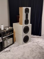
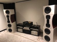
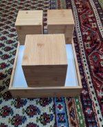
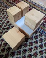
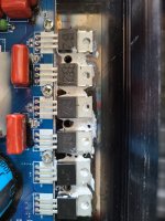
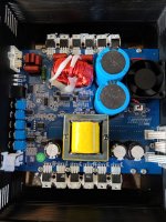
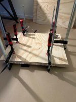
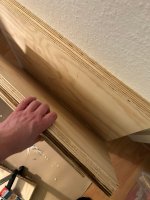
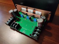
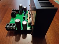
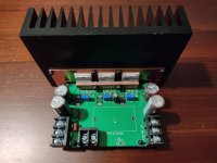
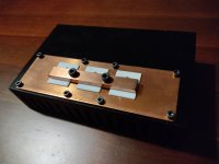
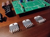
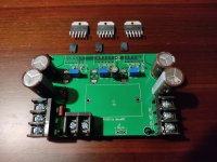
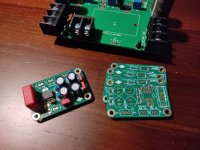
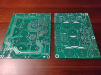
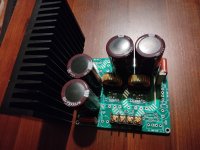
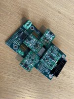
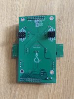
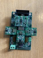
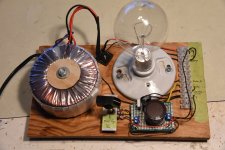
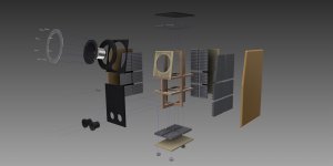
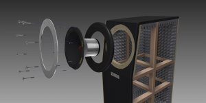
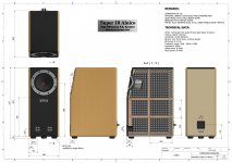
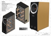
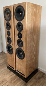
I'd like to offer up my best version of the Thomas Mayer design 6CB5A tube amplifier. Below you'll see some finished pics and some from the construction.

This is his final (best) version as he started out just designing a cost effective alternative to a 300B amplifier, to prove a point. This he feels is better than most 300B amplifiers and he is not alone 🙂 Point proven!

I invite you to visit Thomas Mayer's web site: Vinyl Savor. Thomas is a long-time, acknowledged, master builder, active on forums and has a business where he sells his finest builds, seemingly most of them custom per customer. This design he generously gave to we who are learning 🙂. My take on this is not a two box design like most of his commercial builds but a three box, power and two channel chassis. I also like a vertical format that allows one to work on the amp while operational to make sure voltages are correct during construction. Three boxes make for better lifting too. I am getting tired of my former all-in-one builds that weigh enough to challenge a man of 60+ years. I even use handles! I went a little over-the-top in using a bridge of all mercury vapor diodes instead of Thomas' more modest blended approach but under testing I liked the sound of all MV and they are SO darn pretty. I have, of course, added switches to warm up the tubes before turning on the B+.

This amp has strength and finesse like no 300B I have been able to get MY hands on (I built two and bought two, sold them all). AND, I have five sets of output tubes for this honey. No breaking the bank when the time comes for more tubes. Others have courted the strengths of this unique tube. Me, I'd love it for the top cap alone! I have FIVE strong tube amps to listen to and that means FOUR of them must go. I am looking at leaving the country in 25 months.

Good news, bad news: the good news is that I know the market is small and I will probably sell it for less than parts cost - that's the good news to the buyer - the bad news is that I really don't want to ship this and I live at the top end of a peninsula (Traverse City, Michigan).

I WILL in fact ship it and I know how to pack it for shipping, but... I predict it will cost $150 and I will NOT be responsible for what the gorillas and fork lifts do. I would really like someone to come up for a nice visit to a beautiful, wonderful, foody, artsy lake city, take in the sights, hear this amp and take it home with them.

AND of course, I have more where that came from.

Parts price on this amp is $800. Come on up and haggle, or not - I always have a good bottle of wine or scotch that needs opening 🙂

Cheers!


SE-6CB5A copy 2.jpg
6CB5A frt.jpg
6cb5a again.jpg
right ch nude.jpg
psu.jpg

What kind of caps these are?

Hello,

I work on an old DAC (Parasound DAC 2000) inside which there are a lot of small caps with a yellow color, as shown on the attached photo:

petits_condos.jpg

These are small value: 220pF as squared (squared in red color) in the attached schematic, or 0.1µF for the other bypass capacitors.
extrait_schema_petits_condos_M.jpg

I would like to know what type of caps there are ? they are probably Film caps, but do you know what type of ?

Thank you very much,

Rotel RAP-1580MKII Turn On Pops

I'm looking at this surround receiver that has a mains switch turn on pop (rocker power switch at the back of the unit) from the subwoofer out. It has several line outs aside from speaker outs. There's no pop from the speakers when turning on.

From the mains switch pop, I measured the sub out and there's no DC spike, but there's AC spike anywhere between 20-60mV.
During standby theres no DC on the outputs, turning on with the front panel switch the sub out has either -20mV or 7mV DC offset. There's a thud and the noise tapers down as the offset drops.

With regards to the mains switch pop, I'm going to replace the X2 mains snubber caps for good measure.
I'm not sure what to do about the pop from turning on from standby. Can't find documentations or adjustments for it.
Anyone could point me in a general direction for this?

Okto Dac8 Stereo with Raspberry Pi - power state

Hello all,

I rarely post, but my search-fu has not been able to find an answer to my question. If I install my Raspberry Pi running Moode Audio in my Okto Dac8 Stereo as a streamer, does it remain powered even if the the DAC is turned off, or do I have to shut down the Pi prior to shutting down the DAC?

Thanks for any input/response.

DIY Modex Plate Recipe? VPR / CBA Bass Trap

I want to build some Modex Plate style bass traps. I have seen these referred to as VPR or CBA bass traps.

Does anybody have a tested recipe I can follow? I've seen a lot of talk about the general workings but not a build diary with testing.

I'm also not sure how they should be mounted on a wall. Anything touching the steel plate will surely change the modal pattern.

Power supply with very low current readback resolution / Saluki SPS831 -- really?

I am looking for a programmable power supply that has very high resolution on the current readback value. Searching the internet, I found this:
https://www.salukitec.com/sps81x-series-programmable-dc-power-supply/

According to the specs, the resolution on the current reading is 0.001 mA, or 1 μA. I asked the company for a quote, and they said it's about $700. That's a lot of money, but much less than what other manufacturers would ask for a programmable PSU with the same current readback resolution.

Is this legit? Any thoughts on the SPS831 unit or the Saluki company in general?

Diodes and VBE multipliers.

Since integrated linear amplifiers may use a pair of diodes instead of a VBE multiplier, I would like to ask whether anyone had tried successfully using diodes instead of a VBE multiplier to bias a Class AB amplifier built from discrete components. I am thinking of two or more diodes with a high resistance shunt used as a bias voltage trimmer. Diodes have the advantage of becoming shorted in the event of failure as opposed to a VBE transistor which may become open circuited causing the bias voltage to increase to damaging values. I am thinking about using rectifier diodes as bias diodes.

Help is much appreciated.

ESS AMT Heil Ribbon Tweeter without Model Number (used in ESS PS9a)

This tweeter needs service. Who knows the model of this tweeter? It is in use by follow ESS speakers
ESS PS9A speakers pair with air motion transformer tweeters Photo #219772 - Canuck Audio Mart
and
http://i.ebayimg.com/00/s/MTIwMFgxNjAw/z/8KoAAOSwoydWqRNJ/$_1.JPG
Here pics of the tweeter itself:
http://img.canuckaudiomart.com/uploads/large/86840-ess_heil_ps5a_speakers.jpg
http://bilder.hifi-forum.de/medium/178783/ps8a_244986.jpg
There are no informations under
Heil AMT – ESS Labs., LLC
Maybe it is the predecessor of the AMT-2 - go to
LSV Dieter Achenbach
If I have the model number, I hope to find the instruction manual for disassebmly and reconing.
Thanks for your advices.

Targa 7kd

Hi all,

I have this amp with a shorted output fet. Please advise what parts are to be used as replacements, power supply and output.

Power supply fets are not shorted. Pics attached.

Power supply - H1

Outputs - B2

1679736752963.png


1679736813404.png

Attachments

  • 20230325_104132.jpg
    20230325_104132.jpg
    509.3 KB · Views: 131
  • 20230325_104137.jpg
    20230325_104137.jpg
    604.6 KB · Views: 128
  • 20230325_103850.jpg
    20230325_103850.jpg
    499.5 KB · Views: 127

New sub forum for line and source?

Hello Admin and members
I would like to request an addition to source and line forum, please. A forum for 'Audio Creation' devices. There are some great forums for Audio production out there, but all these lean heavily on brand names. We have the instruments and amps and the PA forum here, but those are again for the larger scale items like power amps and PA as well as troubleshooting and cloning. Basically that, I am noting that the bulk of the forums represent audio reproduction while more and more music enthusiasts are exploring a variety of home music creation setups with the modern range of electronic and computer based tools and instruments

It would be great to have somewhere to discus and evolve DIY music creation tools and devices. Both hardware and software. Things like shop and DIY synths and digital mixers and controllers, monitors as well as the usual DIY shenanigans with upgrading and customising. I really feel we are missing this to fully cover our scope of interests


I have a self-interest in this. Today I am starting a home renovation. I am semi retired and moved into a "tiny home" in sunny QLD with my wife and daughter. We are now expecting another child. It's just been too hot to work in the shed, so I am bringing a part of my workshop inside into the studio area, which is also the main bedroom. It will be awesome to have somewhere to log and request to assist with the challenges of child safety, challenges of audio production and reproduction with limited spaces and such

Another example of self-interest would be, in planning for the renovation, I have been acquiring both production and reproduction hardware. I have now all the mixers and controllers and such here and space planned out. I want to add a stand alone virtual synth based on an Android PC. Will be awesome to have the place to discuss the evolution of this too

The source and line forum would be perfect for this as it is another facet of audio manipulated around line level

Guys, please back me up if you see the merit

Thanks and regards
Randy

Looking for a small signal NPN with no Quasi Saturation: MEASURED DATA

I've got an application in mind for an NPN bipolar, running about 10mA, at low VCE. Imagine a cascoded current source or a full 4T Wilson mirror, that sort of thing. I'd prefer to avoid transistors that exhibit Quasi Saturation at 10mA, because their effective ro (=Vearly/Ice) is poor.

So I decided to measure a few transistors. Here are the results. The ones that my eyeball says "Yes, that looks like Quasi Saturation to me!!" are marked with red arrowheads.

Surprisingly, a few Author Favorite transistors seem to Quasi Saturate at 10mA:
  • Bob Cordell's preferred 2N5551: yes it Quasi Saturates.
  • Douglas Self's 2SC2240BL and MPSA42: both Quasi Saturate.
  • Samuel Groner's MPSA18 (and 2SC2240BL): both Quasi Saturate.
I don't mean to suggest that these fine gentlemen have made a mistake; rather, I'm just pointing out that when I run their favorite transistors at 10mA, the measured IV curves are a bit ugly. Perhaps these honorable fellows would never in ten million years recommend operating these devices at 10mA. I bet that in the future, they certainly do not.

Attachments

  • 2N3904.png
    2N3904.png
    31.1 KB · Views: 2,494
  • 2N4401.png
    2N4401.png
    31.4 KB · Views: 2,469
  • 2N5089.png
    2N5089.png
    39.3 KB · Views: 2,418
  • 2N5210.png
    2N5210.png
    39.1 KB · Views: 2,426
  • 2N5551.png
    2N5551.png
    39.8 KB · Views: 2,465
  • 2N6428A.png
    2N6428A.png
    33.8 KB · Views: 1,140
  • 2SC2240BL.png
    2SC2240BL.png
    35.6 KB · Views: 1,126
  • BC550.png
    BC550.png
    38.3 KB · Views: 1,164
  • BC33740.png
    BC33740.png
    27.9 KB · Views: 1,087
  • KSC945.png
    KSC945.png
    37.7 KB · Views: 1,087
  • Like
Reactions: jxdking

Source for XR1075

Hi everyone,
I am looking for a place to buy BBE-style dual-channel ICs with per-channel control like the XR1075, but I can only find it pre-mounted to processing boards, which I do not want. Does anyone know where I can get these? I have been using two CoolAudio V2153s on one PCB but it makes the schematic needlessly complicated and redundant. Thank you.

2 way with 15LX60v2?

Just wondering if the Beyma 15LX60v2 would be able to used for a 2 way system? I have a 600Hz horn that I plan on using for the HF.

Anyone had any direct experience with this driver and if so what would be the HF limit of it?

Is there another driver that would work better? i.e. I like the 15PR400 but I am concerned about its limited xmax. Also the 15LX60v2 looks like it would work in a smaller enclosure.

Thanks in advance

Richard

Resistor value filter section

Hi guys,

I opened an amp with heavily burned power resistors.
The board itself was burned as well.
I expected it to be the VCC supply of the opamps in the filter section, but I don't read strange numbers there.

Does anyone know how much the resistor value should be? Since they are all discoloured?

Attachments

  • PHOTO_20230324_153239.jpg
    PHOTO_20230324_153239.jpg
    475.3 KB · Views: 80
  • PHOTO_20230324_153315.jpg
    PHOTO_20230324_153315.jpg
    353 KB · Views: 79

Build log 18" subwoofer enclosure

Not sure if there is a build log area, but here goes.

Driver: Rockville RVW1800P8
https://www.amazon.com/Rockville-RVW1800P8-Subwoofer-Woofer-Magnet/dp/B01DP0HKJK?th=1

AMP: GetSHOW 2400W Plate Amplifier with DSP: https://www.aliexpress.com/item/400...o.order_list.order_list_main.5.648c1802L916aM

(If it turns out its not as powerful as I expect, I will likely make it a passive speaker cabinet for now. I think plate amps are hard to gauge, if that is the case I will likely use a Crown amplifier instead. I based the enclosure loosely on the design here: https://www.loudspeakersplus.com/Articles.asp?ID=258

The enclosure is built to also accept other 18 inch drivers, mainly because I wanted to ensure I could actually figure out how to build a decent one before splurging on the RCF drivers I originally wanted. (RCF LF18X401)

Tomorrow after the original glue up for the front element is dry, I will start to assemble the box and put in the bracing. Stay tuned!

Build itself:
Attached is the cut list, with the final dimensions being 780x580x650. Port area is 540cm2 or 10x54cm.

The debt of the port is 37cm, or 34 internal. I could have made this slightly longer for a expected resonance of 35hz, but I think this is fine.

Its made to accept a much more powerful speaker, upwards of 1500w and 125 dB @ 1m (Calculated). I will make two of these to replace some old ELX200's that's disappointed me multiple times..

Besides the cutlist, I used a local sawmill, you also need to cut the baffle at 544 x 37 and a small support at 37x10 cm.


Handles? I will be purchasing some from Adam hall, and a speaker-con connector plate.

Attachments

  • 1672158204938.jpeg
    1672158204938.jpeg
    296.1 KB · Views: 289
  • 1672158226084.jpeg
    1672158226084.jpeg
    327.5 KB · Views: 264
  • 1672158243556.jpeg
    1672158243556.jpeg
    347.8 KB · Views: 271
  • cutsv3-final.pdf
    cutsv3-final.pdf
    68.1 KB · Views: 1,556

WINISD simulations do not match cab design sheets Eminence Lab 15

Hi all,

I've read multiple threads on the subject and I'm getting a bit frustrated 🙂 Before calculating my own box I wanted to 'benchmark' by simulating the cab designs available on the website in WINISD. I don't get why, simulated before with dayton and other drivers, which I built and measured as expected.

I followed the tips on how to input a driver, basically not entering all data but having WINISD calculate as much as possible to avoid rounding errors. I got a 'green message' approving my driver in Winisd which is good. I tried also the export file available at loudspeakerdatabase, but it keeps calculating differently from the cab design sheet, I keep on getting a negative port length. I must be doing something wrong, and getting a bit frustrated.

Strange things is, I do get a vent speed similar (but higher, but that's because i used a round port as most topics say winisd does not calculate rectangular ports correctly) to the simulation. Also the graphs look similar, except the DB are much higher. Also the cone excursion at 600W is completely off.

I've done dozens of simulations, changed the parameters, so I will probably be doing something very wrong, would love to get your help on this! Avoids me building total crap with this driver.


For Sale PA150 LM3886 diy amplifier in copper hardware,DRV134 and gold plated pcb also supplied.

PA150 LM3886 pcb with all components to complete less the audio input capacitor "68€ more shipment"
IC's are new and are not applied on the pcb,like main capacitors,power connectors and SMD output resistors
the other components are already assembled, with genuine components,like on the second picture.
Machined Heatsink with the machined copper hardware and ceramic pads can be supplied the cost is 78€.
DRV134 and gold plated pcb can be supplied if requested cost is 16€
I have also power supply pcb's for who want one model the power supply can be used for powers up to 400watt
and the other for powers up to 800watt, power supply partial assembled as example.
Tracked shipment, shipment to US on request.
Payment by paypal
1679686209702.jpg

1679686330133.jpg

Attachments

  • 1679686209705.jpg
    1679686209705.jpg
    413.1 KB · Views: 104
  • 1679686209693.jpg
    1679686209693.jpg
    313.9 KB · Views: 92
  • 1679686209698.jpg
    1679686209698.jpg
    387.1 KB · Views: 91
  • 1679686330120.jpg
    1679686330120.jpg
    297.7 KB · Views: 94
  • 1679686330123.jpg
    1679686330123.jpg
    388.8 KB · Views: 94
  • 1679686330137.jpg
    1679686330137.jpg
    428.6 KB · Views: 93
  • 1679686403471.jpg
    1679686403471.jpg
    472.3 KB · Views: 87
  • 1679686403465.jpg
    1679686403465.jpg
    503.3 KB · Views: 95
  • 1679687900443.jpg
    1679687900443.jpg
    285.5 KB · Views: 103
  • 1679686403459.jpg
    1679686403459.jpg
    423 KB · Views: 99

For Sale Twisted Pear Buffalo III DAC Board

* * * * * * * SOLD * * * * * * *

Hello,
For sale is an unused 8-Channel ES9018S Buffalo III board which I purchased from a fellow DIYer a while ago, but never ended up using due to lack of time and projects overflow (sticking to my Buffalo II Stereo, and took the resolution to finish building my J2 and M2 Power Amps , Headphone amp, External PSU , I/V converter etc, Sony APM-33 restauration... 😛)

Board is in France, but I can ship worldwide.

Proposed price: XX€ + Shipping (expecting around XX euros PP with Tracking WW)

Any questions, please PM

Attachments

  • 84ED517A-7531-4F26-9CC2-935CE284CBEE.jpeg
    84ED517A-7531-4F26-9CC2-935CE284CBEE.jpeg
    664.7 KB · Views: 141
  • AE0FCF61-E5F9-43F7-B415-EB4F113D5CB2.jpeg
    AE0FCF61-E5F9-43F7-B415-EB4F113D5CB2.jpeg
    581.1 KB · Views: 113
  • 3019DCD9-78A3-470D-9221-DC34120AB9B7.jpeg
    3019DCD9-78A3-470D-9221-DC34120AB9B7.jpeg
    632 KB · Views: 143

Why do amps draw high current if the input jacks are open?

I recently built an EL-34 PP amplifier. When I did the initial power up / testing I hooked up 8R test loads to the speaker jacks but forgot to short the input jacks.

The B+ was down to 350V and EL-34’s where drawing about 90 mA

One I realized the open input jacks where the issue the B+ was 400V and the EL-34’s where drawing 35mA (as designed)

I have a 220K resistor across the input jack(s) and a 1K grid stopper on the 6SN7.

Why does this happen?

Is this unique to PP amps with Feedback? I never noticed this before on SE amps.

Is there a way to prevent this? (Other than shorting the inputs)

SWR amp troubleshooting

Have an SWR Workingman's 160 solid state bass head with no power amp output, any help troubleshooting this appreciated.

It powers on and the preamp section works perfectly. The front panel lights for preamp clip and master limiter are working.

  • On power on, I get about 30v DC on the speaker out that runs down within a minute or so to to about 3-5v and stays there.
  • Can't find a shorted transistor. Can't find a shorted diode. Have checked them all about three times but I could still be missing it.

some voltages B/C/E:

Q10 = -63/-3/-63
Q4 = -3/63/-3

Q9 = -3/-63/-3
Q3 = -3/63/-3

Q5 = -3/-3/-3

...and so on. From the looks of it, the previous owner shorted a speaker lead and things blew up. The rectifier was blown short. I replaced that and it powers on normally. What next?

442963737-Workingman-s-160-Complete.pdf - Adobe Acrobat Reader (64-bit) 3_22_2023 7_03_23 PM.png

Attachments

Inquiries on Class D Amplifier Isolated Feedback

Hi,

I am an undergraduate engineering student working on the design of a GaN-based class D amp as a graduation project, currently in the component testing and implementation stage. Topologically, the circuit design uses a clocked PWM at a switching frequency of 500 kHz. The 8 ohm loudspeaker will be differentially driven using a full bridge configuration with +100 Vdc supply voltage.

For the switching devices I am using LMG3422R030 GaN transistors capable of operating at a switching frequency of over 2 MHz (copy of the datasheet attached below). As part of the circuit design requirements for the given transistor, the PGND is functionally isolated from the AGND. Therefore, if we want to implement a feedback control system, the system itself would have to be isolated as it crosses from the PGND at the output back to the AGND at the input. For isolation, we are using ISO7731 digital isolators (copy of the datasheet attached below).
  1. To what extent does an omission of a feedback system have on the output signal in terms of THD and sound quality? Is it worth it?
  2. What methods are there to implement an isolated feedback control system, given that we have a single 5 V supply rail for the input stage
In addition to the datasheet, a prototype PCB covering the modulation stage (triangular wave generation, biasing & signal conditioning, modulation via comparator) is attached, alongside the results recorded.

Attachments

  • Triangular Wave.jpg
    Triangular Wave.jpg
    384.2 KB · Views: 183
  • Signal Conditioning.jpg
    Signal Conditioning.jpg
    560.7 KB · Views: 157
  • PWM Output.jpg
    PWM Output.jpg
    402.1 KB · Views: 181
  • PCB Board.jpg
    PCB Board.jpg
    514.3 KB · Views: 171
  • PCB Layout.jpg
    PCB Layout.jpg
    122.8 KB · Views: 158
  • ISO7731 Datasheet.pdf
    ISO7731 Datasheet.pdf
    2.3 MB · Views: 280
  • LMG3422R030 Datasheet.pdf
    LMG3422R030 Datasheet.pdf
    1.9 MB · Views: 95

Frankentracer created

Over this weekend, I started collecting parts for a Frankentracer build. In the spirit of Michael Rothacher's original concept, I scrounged up all the electronic parts from my parts graveyard and existing inventory. I only bought a carriage bolt to mount my toroid transformer and rubber feet for the base. So it is truly a Frankenstein's monster.

I built most of it yesterday (Halloween, very auspicious) and finished it off today. I've tested the voltages and all is good, although I haven't tested a SIT yet, so technically Frankentracer has not yet come to life. I think once the light bulb glows, Frankentracer will have taken its first breath.

I used an isolation toroid transformer with centre tapped secondary for power. One half of the secondary (60VAC) feeds into an old bridge rectifier to provide positive and negative voltage outputs. Frankentracer is set up to be configurable with jumpers for either positive or negative Vds and Vgs so I can test both P an N type SITs.

Attachments

  • FrankenTracer.JPG
    FrankenTracer.JPG
    391.9 KB · Views: 313

Cabinet for the Super 10 Alnico in 160 liter BR

Dear musical friends.

I like to built a nice and simple cabinet for my beautifull full range drivers of Audio Nirvana.

The Super 10 Alnico.

Proposal to put them in 160 liter with 2 bass ports.

REMARKS:

MATERIAL CABINET 18mm BLACK AND STANDARD MDF.
SIDE PANELS 19mm SOLID BEECH WOOD.
BRACINGS 44x27 SPRUCE WOOD.
PRITEX 42mm DAMPING GLEU TO ALL INNER PANELS EXCEPT BAFFLE.

TECHNICAL DATA:

Driver: Full Range from Audio Nirvana type Super 10 Alnico.
Volume cabinet: 160 liter.
Sensitivity: 92.86 dB/W(m).
BR port (2x) 70mm diam. x 80mm length.
BR tuning @ 33 Hz.
Frequency range: 35Hz - 20kHz (-3dB).
Impedance: 8Ohm.
Rated power 30 Watt.
Music power 45 Watt.

Attachments

  • an10alnicospecs.jpg
    an10alnicospecs.jpg
    316.1 KB · Views: 181
  • Assembly Super 10 Alnico big 1.jpg
    Assembly Super 10 Alnico big 1.jpg
    91.8 KB · Views: 169
  • Assembly Super 10 Alnico big 4.jpg
    Assembly Super 10 Alnico big 4.jpg
    80.3 KB · Views: 158
  • Assembly Super 10 Alnico big total.jpg
    Assembly Super 10 Alnico big total.jpg
    110.3 KB · Views: 156
  • Assembly Super 10 Alnico big.jpg
    Assembly Super 10 Alnico big.jpg
    148.5 KB · Views: 157
  • Assembly Super 10 Alnico big_page-0001.jpg
    Assembly Super 10 Alnico big_page-0001.jpg
    305.6 KB · Views: 154
  • Assembly Super 10 Alnico big_page-0002.jpg
    Assembly Super 10 Alnico big_page-0002.jpg
    343.8 KB · Views: 156
  • Assembly Super 10 Alnico big_page-0003.jpg
    Assembly Super 10 Alnico big_page-0003.jpg
    296.7 KB · Views: 148
  • Assembly Super 10 Alnico big_page-0004.jpg
    Assembly Super 10 Alnico big_page-0004.jpg
    250.3 KB · Views: 139
  • Baffel Alnico.jpg
    Baffel Alnico.jpg
    108.2 KB · Views: 130
  • Bracing big 1.jpg
    Bracing big 1.jpg
    91.6 KB · Views: 129
  • Bracing big 2.jpg
    Bracing big 2.jpg
    89 KB · Views: 141
  • Opstelling Super 10 Alnico big 1.jpg
    Opstelling Super 10 Alnico big 1.jpg
    286.5 KB · Views: 143
  • Opstelling Super 10 Alnico big 2.jpg
    Opstelling Super 10 Alnico big 2.jpg
    279.4 KB · Views: 140
  • Opstelling Super 10 Alnico big 4.jpg
    Opstelling Super 10 Alnico big 4.jpg
    245.8 KB · Views: 168

Brzhifi JLH 1969 diy mods?

Hello not so long ago I got a JLH build from brzhifi from ali

AU $195.08 | Hood 1969 Class A power amplifier with FET BRZHIFI 1969-2020 tube amplifier sound quality
https://a.aliexpress.com/_mNcq9P0

It’s ok but I’m a diy freak are there any tweaks i can do to get more out of this?

Component changes or a bigger transformer?

Any tips appreciated.

It is always going to be driving full range speakers

PCB Material Copper Clad 2 types

(I'm going to keep this a standard schpeel, I hope the Mods don't mind. If so please let me know)
I'll be popping in fairly often. I'm cleaning out and stumbling on things that the community might need.
Certainly not looking to get rich here. Make me a reasonable offer on most of the stuff I unearth and I'll probably take it. Seems a shame to have it in a cardboard box somewhere if it can be used.
Please keep it in the US - I don't really have the time to do paperwork, and i don't want to take the time to research what something might be worth.
So make a reasonable offer - PM Me - remembering it's going to take a few dollars to get it to you. I do appreciate PP F&F.


I have too Much PCB Material here. There are two types. They are both double sided. They are cut into approximately 12" x 12" squares. It is a straight, but rough cut - you can slice your hand on the edges. There are some surface scratches and the occasional surface corrosion. Pretty thick copper here.

These will make it into a Large USPS Flat Rate Box ($20). This is really the only way to sensibly ship multiple pieces, especially the thick stuff. I wouldn't load a box with too many for the fear it might break through.

NOT SURE WHAT IT'S WORTH - MAKE ME AN OFFER PER PIECE.

1) This material is 1/8" thick. in the world of PCB material that is insanely thick and heavy - you need to make sure the leads of your components are all long enough, but it makes for a strong board. This does take a while to etch! Approx 3 thousandths measured. The substrate is black and makes a striking board if you do your part. I have qty 14 12" x 12" pieces available


1679346096401.png
1679346240851.png
1679346829726.png


2) Much thinner than the first. Double sided copper. Has the standard PCB 'green' color when etched. When you bend this it actually stays where you bent it. you can actually curve it and it stays curved ??! I think the core is thin and soft and the copper is thick so....well...
I have I have qty 11 12" x 12" piece
s available


1679346373121.png
1679346438571.png

Ah Tjoeb Tube Clock

For sale Ah Tjoeb tube clock, used but in nice condition with original transformer and reserve tube. I dont know if its working, I have become this from good friend of mine, he take this from working tjoeb cd player, becose the display was broken and remote reciever also. So maybe someone can use this in his project. Price is 60eu plus 10 eu shipping inside EU.

Attachments

  • IMG_20230324_143816.jpg
    IMG_20230324_143816.jpg
    633.5 KB · Views: 154
  • IMG_20230324_143823.jpg
    IMG_20230324_143823.jpg
    501.3 KB · Views: 140
  • IMG_20230324_143827.jpg
    IMG_20230324_143827.jpg
    695.9 KB · Views: 157

Le Monstre vs JLH 1969

In past I build original version of JLH1969 amplifier and even with junk parts this amp give me glimpse of strue figh fidelity stereo. Now after some time, parts for Le Monstre is my working desk (only few capacitor is missing). I would like to hear what is sound quality of Le Monstre amplifier from the guys that have this amp in operation before is my soldering iron warmed up...It is Le Monstre better or worse of classic JLH (power is not the same and topology is different).

Cantius VI (6) from German's Brand ASW (Accurate Sound Wave) - Impedance-Plot and Schematic wanted

Test review of this model is to find in German's magazine "Audio", issue 12/99 (go to the last both images).
Maybe one of the member can upload this review.
Unfortunately the available reviews on the website under
https://web.archive.org/web/2016040...es/messen/aktuelles-start.php?sprache=english
contain only test reports of newer models.

Thank you very much

Attachments

  • ef06173b43d48c07f3eb46044979.jpg
    ef06173b43d48c07f3eb46044979.jpg
    275.5 KB · Views: 304
  • b170c68e455daf56bc83e77c6028.jpg
    b170c68e455daf56bc83e77c6028.jpg
    554.6 KB · Views: 241
  • 8be9ef2e483a96f0b4d9274a8fa9.jpg
    8be9ef2e483a96f0b4d9274a8fa9.jpg
    458.8 KB · Views: 306
  • 6d3bdaea4bedbc71d29c4b9b5713.jpg
    6d3bdaea4bedbc71d29c4b9b5713.jpg
    413 KB · Views: 417
  • s-l1600 (1).jpg
    s-l1600 (1).jpg
    459.1 KB · Views: 309
  • ASW Audio 12-1999.jpg
    ASW Audio 12-1999.jpg
    311.9 KB · Views: 254

FS: Markaudio MAOP 11.2

Hi all, sell a matched pair,bought June 2022(invoice Will be provided)
Break in was done in air at radio level with Guitar and vocals First 80 hours and slowly increase After that. They have actually approx 200 hours.
Request Is 220 Eur plus shipping of 40 Eur for Europe.other Countries Just ask .
PayPal Is fine.see pictures

Attachments

  • IMG_20230318_093441.jpg
    IMG_20230318_093441.jpg
    371.9 KB · Views: 182
  • IMG20230318091721.jpg
    IMG20230318091721.jpg
    338.8 KB · Views: 144
  • IMG20230318091808.jpg
    IMG20230318091808.jpg
    195.6 KB · Views: 135
  • IMG_20230318_093502.jpg
    IMG_20230318_093502.jpg
    233.4 KB · Views: 133
  • IMG20230318093624.jpg
    IMG20230318093624.jpg
    314.6 KB · Views: 161
  • IMG_20230318_094402.jpg
    IMG_20230318_094402.jpg
    490.1 KB · Views: 182

Coiled coils

I don't know if this could be useful for anything audio-related or anything at all, but the idea of coiling a coil iteratively is geometrically fascinating enough.
Could a coiled (coiled coiled...) coil perhaps offer some fun insights into symmetry and resonance?
How would I best coil coils without complex machinery? Could a "normal" winding machine be utilized for iterative coiling? (Let's say if I found a company with a programmable winding machine and asked them to do this)
Maybe with the help of a structural support for each step of the winding it'd be a matter of gentle enough operation to keep such a structure together.
Using a permeable supporting structure would be interesting especially.

I found only just one blog that touched a little bit on coiled coils:
http://harmoniouspalette.com/InductiveCouplingGeometry.html

Need 2SD863 equivalent

Hello,

I have a Rotel pre amp tuner with a bad 2SD863, every equivalent I have found is also obsolete, I could order them from aliexpress or ebay but prefer to get modern equivalent from Digikey that I know is genuine

anyone know of a way to find a modern equivalent that digikey would have in stock

https://datasheetspdf.com/pdf/652079/SanyoSemiconductorCorporation/D863/1

  • Poll Poll
Seeking help with choosing PSU

Which one would you choose for a main router?

  • https://www.aliexpress.com/item/4001105205302.html

    Votes: 0 0.0%
  • https://www.aliexpress.com/item/1005004876089405.html

    Votes: 0 0.0%
  • https://www.aliexpress.com/item/1005004780740798.html

    Votes: 0 0.0%

Hello everyone,

I'm in a process of choosing linear PSU for my main router and I'd like your kind help with that.

Setting is as follows: It would be plugged into a low-end filter (Oehlbach Powersocket 907), so some more filtering capacity won't hurt and it won't be connected to my main system, just to a "distribution" part of the network.

Thanks for all inputs, cheers!

JBL 035TIA Tweeter dampers

Hi All,

I have a pair of JBL L1 speakers and I would like to "refresh" their 035TIA tweeter's dampers.
I've been reading and watched few videos about how to do it but got confused.....

as mentionined on some websites (and in here) there are 2 different dampers in each tweeter, 1 is 6mm in diameter and 3mm high and made of rubber or hard foam, the other one is about 20-22mm in diameter and 10mm high made of very soft foam.

Now some sources mentioned that the smaller (6mmx3mm) should be placed on top of the pole piece, just below the larger damper and the larger, softer 20mm dia damper should be placed on top of the smaller damper and "push" the tweeter dome from below, so bassicaly the smaller damper gives the larger damper a "boost".(drawing 1)

Other sources mentiond that the lager damper should be placed on top of the pole piece and the smaller damper should be placed on top of the larger one so the smaller damper is "pushing" the tweeter dome from below.(drawing 2).

I see no sense in placing a smaller damper below the larger damper to give it a "boost" because if so why JBL didn't make a 13mm high damper from the first place? what's the reason for "complicating" things with 2 dampers?
What is the benefit of using a smaller in diameter and harder material damper below a soft larger damper?

My common sense say's that the larger damper should be placed on top of the pole piece (and cover the whole pole piece top surface for more stable base) and the smaller damper needs to be placed on top of the larger damper so the larger damper acts as a spring to the smaller damper and the smaller damper will touch only a specifiec point at the center of the back of the dome (drawing 2) .....maybe I'm wrong but that's my common sense.

I'll appreciate if someone that has a definite answer for what is the right way to do it and done that before will share his knowledge.

Thanks

Attachments

  • JBL 035TIA dampers.jpg
    JBL 035TIA dampers.jpg
    15.2 KB · Views: 84

Taramp HD3000

hello everyone and thankyou all for helping my amp went into protect mode so i opened it up and found some capasitor or resister that are burnt with soem blue chips too i cant find anyone who has done a repair to this part im a complete amateur but i do have a solder and willing to try and fix it myself

Attachments

  • image.jpg
    image.jpg
    567 KB · Views: 232
  • image.jpg
    image.jpg
    478.5 KB · Views: 192

10inch woofer for dipole advice?

Hello.

I’d like to build a single 10” dipole woofer similar to the linkwitz lxsub to be used/experimented with my (currently in build) Linkwitz Pluto (singular as it’s an experiment in mono playback). Crossover anywhere between 60-120hz (need to experiment). Crossover and dipole correction in minidsp. Extension down to 30 or even 40hz is good enough for me, this is more an experiment on off loading the mid bass and room interaction with dipole vs monopole. Music of choice for me is jazz, folk, bluegrass. Must be 10” for WAF.

Curious if people had any suggestions on a good woofer to use. I don’t mind ponying up for the same Seas L26RO4Y as the lxsub if that’s really the right choice but it would be great to spend less. Especially as I live in an apartment these days and my playback levels tend to be on the lower side. Would a peerless XLS 830452 like he used in Orion make a valid alternative if I can snag one? Any Dayton options that are good? Other stuff I should consider?

Even though this is a bit of an experiment, I don’t want to get something super cheap, decide I like it, and then have to buy something else and have to find another home for the first woofer I bought.

Thanks so much for any feedback/suggestions!!

miniDSP SHD or 2x4HD

Hey Guys,

I've just bought a miniDSP SHD to get an all-in-one unit to cover both streaming and preamp duties and employing an active crossover.

I'm not super impressed by the look and feel of the unit. It feels very flimsy. Sound-quality seems acceptable, however.

Here's my question:

Does it make more sense to just get the miniDSP 2x4HD and get a better streamer, dac, and preamp, or will the 2x4HD also be a sort of bottleneck for future upgrades to sound quality?

Hope you can help,


Mads

Super V/i converted (LL1684 )

Super V/I converted For DAC

OUTPUT STAGE WITH LL1684 LUNDAL TRANSFORMER

After many listening tests with my friends I consider this configuration as the best.

The LL1684 with the amorphous core is the best choice as output transformer.
This is the circuit diagram V / I LL1684: Super V/I

Attachments

  • Suppler-V-I-LL1684-for-DAC.jpg
    Suppler-V-I-LL1684-for-DAC.jpg
    518.6 KB · Views: 8,341
  • ll1684,2.jpg
    ll1684,2.jpg
    302.6 KB · Views: 5,279
  • LL1684-OUT-ES9018-pcb.jpg
    LL1684-OUT-ES9018-pcb.jpg
    278.9 KB · Views: 4,812
  • ll1684,3.jpg
    ll1684,3.jpg
    321.2 KB · Views: 4,818

Simple to build Synergy horn to go with tham15?

So with everyone's guidance (thank you) on this forum, I was able to CNC and build a pair of Tham15's and am blown away.

I need tops now...

SynTriP would be ideal, but after scouring for plans, they ended up just being to complicated for me. (beautiful speaker tho)

Im wondering if anyone can recommend a synergy design to go with my THAMs that is easy and cost effective to build but still has that magic hologram sound? and can keep up with (4) thams (eventually).

Id like to avoid making a custom HF driver adapter if possible, and hoping to find something with plans LOL

Thanks

Selecting Capacitor(s) and Resistor(s)

There are several places where the schematic is clear and those who have built this mono block before seem unwilling to help now that I have put significant time into the pre build. So, I am not going to be deterred, simply see it as a learning opportunity to understand amplifier design and specification (I see no point wasting energy getting upset, raised to keep smiling and laughing). This is the highest resolution available, glad there is anything.

What is the purpose of C9 capacitor, please?
Screen Shot 2023-02-06 at 8.47.51 PM.png


What about C2 capacitor, please?
Screen Shot 2023-02-06 at 8.50.15 PM.png


What about C7 capacitor, please?
Screen Shot 2023-02-06 at 8.51.12 PM.png


Onto the resistors.

I think R1 is 150kΩ, R2 a stab in the dark of 390Ω, R3 guessing 100Ω, and forget trying to guess R4. If know the purpose of this arrangement and preferably how to specify, can figure it out.
Screen Shot 2023-02-06 at 8.53.07 PM.png


Lastly, the purpose of R8.
Screen Shot 2023-02-06 at 8.58.18 PM.png


Thanks in advance!
  • Like
Reactions: TonyTecson

Centre channel

Had an extra waveguide and DE250 lying around so decided to try running as a two way with the centre
from 700hz up with a 48db linear phase with the DEQX. So far really impressed! At least in my room
I'm getting alot more detail. I got the idea from reading about the OPSODIS technology and wanted
to build a whole rig. But I think just a setup like this might be sufficient. Im still in the honeymoon
phase with it, so maybe it gets annoying after a while, but enjoying ATM.

I think having the same directivity between the centre and side channels needs to match. But this setup
opens up a few more options. Such as running drivers that do upper mids better for the sides and
somethign with a really nice top end for the centre.

Anyone else played around with this?

Attachments

  • 1679549095852.jpeg
    1679549095852.jpeg
    181.4 KB · Views: 125
  • Like
Reactions: Lynn Olson
Projects by fanatics, for fanatics
Get answers and advice for everyone wanting to learn the art of audio.
Join the Community
507,724
Members
7,885,861
Messages

Filter

Forum Statistics

Threads
406,121
Messages
7,885,861
Members
507,724
Latest member
Samsquatch01