I have some 6C33C and 6C41C laying around and am itching to build something for them. Initially, I thought about using the 6C33C (single cathode) in a SET amp with a pair of 800:8-ohm transformers I have on the shelf and 6C45-PI as drivers. The amp models very nicely in SPICE, and appears to yield upwards on 10W output.
And then I saw Tim Mellow's OTL... It is an intriguing design. But, I have some concerns about it.
1) Is it safe for my speakers? I know the 6C33C is supposed to be very stable once burned in, but what about at initial turn-on? Won't the output see a hefty DC spike while the 6C33C are waiting to conduct?
2) Can one build the power supply so that heaters are switched on first, and then the high voltage supply is switched on after warming the tubes? Would this be more dangerous for the speakers (by possibly causing the 6C33C to conduct before the bias supply has stabilized)?
I'm sure I'll have more questions...
Thanks!
I have some 6C33C and 6C41C laying around and am itching to build something for them. Initially, I thought about using the 6C33C (single cathode) in a SET amp with a pair of 800:8-ohm transformers I have on the shelf and 6C45-PI as drivers. The amp models very nicely in SPICE, and appears to yield upwards on 10W output.
And then I saw Tim Mellow's OTL... It is an intriguing design. But, I have some concerns about it.
1) Is it safe for my speakers? I know the 6C33C is supposed to be very stable once burned in, but what about at initial turn-on? Won't the output see a hefty DC spike while the 6C33C are waiting to conduct?
2) Can one build the power supply so that heaters are switched on first, and then the high voltage supply is switched on after warming the tubes? Would this be more dangerous for the speakers (by possibly causing the 6C33C to conduct before the bias supply has stabilized)?
I'm sure I'll have more questions...
Thanks!
I built the Tim Mellow OTL a couple of years ago, and since then I've been using it as my main amplifier. I've never had any trouble with DC on the output, and in particular, no problems as it warms up.
Acually, I think it is much better not to have any delayed application of the HT. If you do have a delay, then there can be a big current "slam" when the HT is applied to the already-warmed-up tubes.
The natural warming up processes in fact take place in the appropriate order: the EF86 drivers and the ECC83 input tubes warm up and become conducting first, so the biasing is settled by the time the much heftier 6C33C output tubes are becoming conducting.
One might worry about what would happen if one of the EF86 driver tubes failed (in the sense of becoming non-conducting), since then the potential on the grid of the associated 6C33C would be lifted towards its anode voltage by the 100K resistor, driving it into strong conduction. I've never had any problems so far. It is very important, of course, never to pull out one of the EF86 drivers while the amplifier is operating!
I am using 10-turn trim potentiometers I bought at Mouser; I can try to check later exactly which ones. They cost about $10 each, as far as I recall. It is good to use multi-turn pots, to allow fine adjustments to the biasing.
Chris
Also, is there an advantage to building the +/-150V supply as drawn in the schematics? Seems that one could just pick up a pair of 2200uF, 200V caps and save both money and space.
There's no advantage to using the series-connected low-voltage capacitors; it is much simpler and probably preferrable to use 200V capacitors like you said. He probably only did that because of what was available to him at the time, I suspect.
I checked on the trim pots I used; they are wirewound. I mis-remembered about the number of turns; my 1K pots are 3-turn, and the 10K pots are 5-turn. (Mouser numbers 882-MW22B-3-1K and 882-MW22B-5-10K, in fact.) They seem to be a bit more expensive than I remembered too; more like $15 each.
I'm using dual 117V to dual 117V toroids too, for the main HT supplies. In my area the mains voltage is typically about 120V. I wouldn't think that the extra voltage from a 125V mains supply is that big a deal.
Chris
Thanks- I think I will go with wirewound as well since they are easier to find.
I am worried about my capacitor options... Since my mains voltage is higher than normal, my -430V supply might sit closer to -500V (according to SPICE). Sourcing caps to deal with this is somewhat difficult and pricey. It looks like I would need 550V caps to be save, but Mouser only stocks one. If it isn't too much trouble, can I ask how high your -430V supply runs?
I am worried about my capacitor options... Since my mains voltage is higher than normal, my -430V supply might sit closer to -500V (according to SPICE). Sourcing caps to deal with this is somewhat difficult and pricey. It looks like I would need 550V caps to be save, but Mouser only stocks one. If it isn't too much trouble, can I ask how high your -430V supply runs?
There is something puzzeling me (happens from time to time  ) Tim Mellow states, The obvious choice of output tube was the Russian designed 6C33C triode, because a single pair can deliver 2.5A into an 8Ω load from a moderate 150V rail. This enables the amplifier to deliver 25W into an 8Ω load or 40W into a 16Ω load But the data say otherwise
Mona
) Tim Mellow states, The obvious choice of output tube was the Russian designed 6C33C triode, because a single pair can deliver 2.5A into an 8Ω load from a moderate 150V rail. This enables the amplifier to deliver 25W into an 8Ω load or 40W into a 16Ω load But the data say otherwise Mona
Attachments
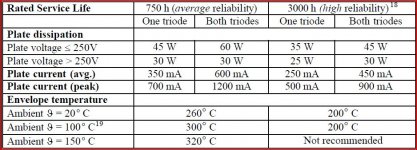
Tim Mellow's figures are pretty accurate; the data sheet understates the peak current capabilities of the 6C33C. And although obviously one would not want to be "pushing the envelope" to such an extent for long periods, there are a couple of things that help to mitigate the "abuse" of the tube:
Firstly, even if one were running a continuous sine wave signal at 25W into an 8 ohm load, each tube is only called upon to pass that sort of heavy current for one half of the sinwewave cycle; one tube is conducting during the upper half of each cycle and non-conducting during the lower half, and vice versa for the other tube. What really counts is what the power dissipation in a given tube averages out to over the course of a *complete* cycle, and that complete cycle includes a half cycle with essentially no power dissipation at all. So although outputting 25W into 8 ohms would certainly exceed the stated maximum power dissipation of the 6C33C by a significant factor, it is not grotesquely more. And the 6C33C is a pretty rugged tube. Of course it is not advisable to run 25W into an 8 ohm load for more than a rather brief period of time.
The other point is that in practice one's listening does not consist of extended periods of listeming to a sinewave at 25W. In normal usage lsitening to music, the power output will only very intermittently be reaching the 25W regime, and so this will mean the time-averaged power dissipation will be much less than that for a continuous 25W sinewave.
I have made measurements on my amplifier and found I could reach almost exactly 25W rms into an 8 ohm dummy load, just at the point where clipping began. (I think Spice simulations are not very trustworthy when "pushing the envelope," since they would be critically dependent on the details of the modelling of the tube characteristics in the high-current regime where no very good data are published.) I only kept the level at 25W for the few seconds necessary for making the measurements.
Chris
I don't think it quite hits the 25W mark. In my SPICE simulations, the waveform starts being visibly clipped at about 10.7Vpk output.
In fact you would need 20V peak for 25W into 8 ohms. As per my previous posting, I suspect your Spice simulation is considerably underestimating the capabilities of the 6C33C, because the modelling of its characteristics at high plate current is not good. My actual measurements on my amplifier were almost exactly in line with 25W at clipping.
I tracked down a calculation I had presented on another forum a while ago, for the power dissipation in each 6C33C when running at 25W into 8 ohms. It's a bit of a crude estimate, but I think it is in the right ballpark:
"Here is an estimate of the average power dissipation in each 6C33C output tube when the OTL amplifier is delivering 25W into an 8 ohm load. In this calculation, I assume the supply rails are +/- 150V. Let us consider the upper 6C33C tube, whose anode voltage is therefore +150V. It will be conducting and dissipating power during the upper half of the sinewave, and essentially non-conducting during the negative half. The discussion for the lower tube will be analogous.
For a sinewave at angular frequency w, the current will be I = (5/2) Sin(w t) during the positive half, i.e. 0 < t < Pi/w, and the voltage on the cathode will be 20 Sin(w t), since 25W into 8 ohms means a peak voltage of 20V. Therefore the anode to cathode voltage is V = (150 - 20 Sin(w t)) and so the instantaneous power dissipation is
P = I V = (5/2) Sin(w t)(150 - 20 Sin(wt)).
Integrating this over the positive half of the cycle (0 < t < Pi/w), and adding zero for the negative half cycle, gives the total dissipative energy in the upper tube per cycle. Dividing by the period (2 Pi/w) then gives the average power dissipation in the tube; it comes out to be 25(30-Pi)/(2Pi) which is about 107W. This is indeed considerably more than the rated maximum dissipation of 60W, but it is not astronomically more. Tubes, unlike transistors, don't typically fail catastrophically if pushed a bit beyond their limits. And in practice, when used for listening to music rather than running continuously at 25W sinewave into 8 ohms, so that the amplifier is only intermittently being called upon to output the full 25W, the tubes seem to last pretty well, for a good few years."
Chris
Yes, I'm using an Amphenol inrush limiter. I'm travelling at the moment, and won't be back home for a while, so unfortunately I can't check the model number (or those voltages you were asking about). I think it is either the CL-40 (which is 6A) or else the CL-21 (8A). (My amplifier is stereo, and the power supply is for both channels.)
Chris
Chris
Since my power supply will run the voltages higher than the schematic specifies, would it be better to change the 1k dropping resistors to get closer to +146V and -430V, or should I leave everything the same so I have the same 'relative drop' for these? I'm guessing it will be fine as is, but want to be cautious since it will be DC coupled to my speakers...
I haven't got to it quite yet... Have all the parts except the power transformer. Some other projects got pushed ahead of the OTL after my 6C33C SET turned out so well. Got to get my office system up to par now... Hopefully I'll get to the OTL shortly after the new year.
Looks like the Graaf GM20 schematic can be found here.
Looks like the Graaf GM20 schematic can be found here.
- Home
- Amplifiers
- Tubes / Valves
- Questions about Tim Mellow 6C33C OTL