Hello Needtubes & Brommermartin,
Did you guys finally build this? I am getting ready to take a plunge and would love to learn from your experiences. Love to see any pictures too.
TIA,
Did you guys finally build this? I am getting ready to take a plunge and would love to learn from your experiences. Love to see any pictures too.
TIA,
Matching 6C33C
How can I calculate transconductance (gm) for individual 6c33c in order to match pairs of such tubes.
I have built a test banch with +150V psu for the plate and variable bias supply -35 to -70V.
Thanks in advance.
How can I calculate transconductance (gm) for individual 6c33c in order to match pairs of such tubes.
I have built a test banch with +150V psu for the plate and variable bias supply -35 to -70V.
Thanks in advance.
To calculate gm, you need to know the change of Ip vs Eg, e.g., measure the plate current at Eg = -35V and -36V, subtract the two current readings and that's your gm.
Ok, I'll do this later.
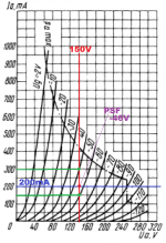
But how shall I interpret the gm value from the datasheet, which is 40 mA/V corelated with the graphs.
At 150V plate, result 200 mA at -50Vug and 80 mA at -60ug. If I do right, DIp=120mA and Dug=10V so gm must be 120/10=12 ??? or not.
But how shall I interpret the gm value from the datasheet, which is 40 mA/V corelated with the graphs.
At 150V plate, result 200 mA at -50Vug and 80 mA at -60ug. If I do right, DIp=120mA and Dug=10V so gm must be 120/10=12 ??? or not.
The 40mA/V spec is given at much higher Ip (470mA-630mA), I doubt you want to test the tube at such high current.
If I do right, neither at 550mA the gm can be 40mA/V accordinf with the tube datasheet graphics.The 40mA/V spec is given at much higher Ip (470mA-630mA), I doubt you want to test the tube at such high current.
In anny case my project (Tim Mellow OTL) works at +/-150V 200mA and -50V ug.
The problem with those tubes is huge disperssion of ug values an I must somehow to match them.
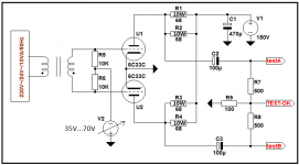
I also intend to buid a dynamic matching tester as attached schematics. Do you think it shall be useful?
Attachments
It depends how much time and money you want to spend on matching the tubes, think about how many tubes you need to go through to have a matched pair... It might be easier to just purchase matched sets, or modify the bias network, so you can at least adjust the idling bias for each tube and rely on NFB to correct the mis-match in gm.
For the moment I have 40 pcs and I'm waiting for anoter 20. I know is not enaugh but it's a starting poin.
Buyng matching sets...honestly I do not trust. Eventualy thei can mach against plate curent if they can. I have hav allready some atempts with 0 results.
Changing the main ideea of Tim schematics regarding the bias, I am not such an expert so I am glad with what I get...it sounds great.
Thaks a lot for your help and paciens.
Could you please post the schematic? I think there are several versions of the Mellow’s OTL out there.
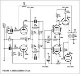
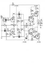
Here you are the original Tim schematics as well as what I have changed (separated PSU, CCS first stage, 32 ohms out for my ESL6with 23 ohms imput trafo modified)Could you please post the schematic? I think there are several versions of the Mellow’s OTL out there.
Attachments
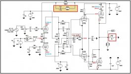
I arranged the model around the PSF where the amplifier works (Ua = 150V, Ia = 200mA, Ug results -46V)
In this area centered on 150V, I can not get gm> 15mA / V
In fact, on the test bench I got at 140V (as I have a smaller transformer and does not carry) with Ug = -46V and Ug = -50V the worst gm was 6mA / v and the best 12mA / V. most values ranged from 8.7 to 11.2 mA/V
In this area centered on 150V, I can not get gm> 15mA / V
In fact, on the test bench I got at 140V (as I have a smaller transformer and does not carry) with Ug = -46V and Ug = -50V the worst gm was 6mA / v and the best 12mA / V. most values ranged from 8.7 to 11.2 mA/V
Attachments
I think you should be able to adjust the idle current of the output tubes using the Bias and the Offset pots (as shown in Mellow's schematic).
More recently, I am stressed by the idea of finding a better tube instead of ef86 in my scheme. That's because over time, the only problem was the premature wear of the two pentodes, which can lead to a collapse when the power tubes remain without bias. I noticed that one of the two pentodes works at the limit in Tim's scheme which can cause wear. What can you suggest?
Hello Needtubes & Brommermartin,
Did you guys finally build this? I am getting ready to take a plunge and would love to learn from your experiences. Love to see any pictures too.
TIA,
Hello niceguy... below ther's a link where you can find a lot of pictures of Tim Mellow OTL amp...
OTL Power amplifier - ARESAUDIO electronics & audio engineering
Bye
Gentlemen, project started, I'm going to build this THING.
Since this is a design mainly focusing on the Russian 6C33C-B (6S33S-V) I decided to go with all-Russian tubes, because "why not". That would be even more fancy I think.
I have very good experience with 6N1P-EV-s (no western equivalent) in an OTL HP amp, so in Tim's design I'm going to replace EU tube types with Russian equivalents.
- ECC83 -> 6N2P-EV (both 6V but heating + screen rewired for the Russian one accordingly)
- EF86 -> 6J32P (or some call it 6Z32P)
Apart of this I'm thinking about a low-noise, well designed/well filtered all-SMPS solution but sadly can't find SMPS for the 150V anode voltage. (Tbh. only looked at Meanwell 'til now).
6V would be easy normally but with regards to the 150V cathode potential difference between the two output tubes I'm confused if I can heat them with an SMPS at all - or is there any kind of trick to solve this ? (If possible I'd use parallel heating through the whole design, so 6V).
And yes, I'm going to heat at 6.0V not 6.3V. Russians' lowest heating is usually spec'd at 5.7V so with a moderate 6V they're still ok from anode point of view too and I win some
extra hours of lifetime maybe.
What do you think ?
It would just look like a flat metal box with the tubes standing on it, no trafos at all. That must be absolutely funny, apart from the really unusual all-smps idea itself. (For some hardcore audiophiles it might be the deepest hell, but I don't really care, I rather find it interesting and tempting to do it and see how it might perform - I hope it won't be like p*****g against heavy wind - sorry for the analogy 😀 ).
Last edited:
Why not run the filaments in series so you can use a 12v supply? I hear it’s better for the socket contacts which run really hot.
Because filaments of triodes - even within a bulb for dual triodes - tend to have some manufacturing spread and serial connection makes a - probably negligible but still existing - bigger difference in power than parallel if there's any delta in filament resistance.
P=U^2/R.
- change of R by 10% means 10% change in power when connected in parallel
- change of R by 10% means 23,4567890123...% change in power when connected in series (and one filament has a resistance 10% higher)
P=U^2/R.
- change of R by 10% means 10% change in power when connected in parallel
- change of R by 10% means 23,4567890123...% change in power when connected in series (and one filament has a resistance 10% higher)
Hello Vortex! Wish You luck and success in this project!
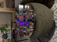
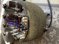
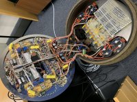
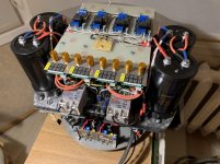
I finished mine just before year end when the heating session starts 🙂
I used 1:1 amp solution from Mellow schematics but power plant is totally different. +/-150 rails are coming from four (two per channel) SMPS (adjustable from 0 to 160V/3A - from Aliexpress), 2x16000mkF per channel,
one common 6,3V SMPS for pre stages heating. One 24V SMPS for general use (timers a.s.o). 2x280V linear regulated supply for BIASing - extending -150V rail - both channels separated and 4x5V linear regulated and separated supplies for indicators (VU and DC0 and 2xIA). Switching ON will happen in four steps with timers. Oops - forgot - output stages heated 24Vac i.e. both tubes in one channel in series, channels in parallel - one 210VA toroidal tranny can handle the business.
Result: extremely satisfying. Amp is dead quiet with huge headroom and
dynamics. FR - from... to... You don´t need more...
Tubes: 6C33C, 6J32P and 6N2P
Tried also ECC83 but it sounds a bit "crispy" for me as well as 6N2P-EV´s...
Just for fun couple of pics also!
Attachments

- Home
- Amplifiers
- Tubes / Valves
- Questions about Tim Mellow 6C33C OTL