Holy ****, that's some serious (and fun and exotic) kind of build, omg.. congratulations, it look so cool 
Can you send me a link with that specific aliexpress smps ? (+/- 160V).. in private also ok. I really like your extraordinary design and I'm glad to see you also swapped original western tubes to eastern equivalents, how cool. I'm going to make a 3-way monitor-class large-ish speaker with active XO and I thought I would drive the tweeter region with such an OTL while the midrange would get something more powerful (Class AB KT150 with tranny) and the deeps Class D. Anyway, it's great to read about your success, from build point of view it looks like a professional job.
Is there any reason you put kind of a screening between the small signal tubes and the big ones ? Do the 6C33C-B-s emit some kind of "radiation" the smaller tubes would otherwise hear ?
Cheers and thanks again.. what a great amp.
Hi Vortex and thanks!
I used these - 480w Digital display Switching Power Supply 5V12v 24v 36v 48v 60v 160V Adjustable AC DC Converter 80v 120v 220V LED Power supply|Switching Power Supply| - AliExpress
but also these are good (ordered already for next project) - Adjustable DC Regulated Switching Power Supply AC110V/220V to 0 160V 3A 0 480W HJS 480 0 160 Transformer Power Unit 160V 480W|Switching Power Supply| - AliExpress
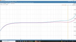
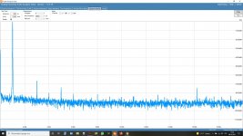
Given ripple is 100mV which is good enough for this voltage.
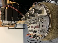
The reason of the screen was just to protect the upper surface of the amp from excessive heat generated by 6C33 because the heat released is passing away mostly through the thermal radiation (50-60W per tube!). I was scared a bit not to install this screen too close to the tubes because it will cause a thermal mirror and possible "thermal runaway" for 6C33´s. Fortunately I left enough distance between tubes and screen and no problem occured even with full power. But definitely keep at least 5cm in between tubes, otherwise You can face trouble with overheating and thermal unstability. I have also installed two fans (look at back side) 24Vdc running at 13Vdc to lower the noise created. This will grant the air exchange for the power plant. Temperature inside the "Rolling Stone" in normal working condition is 35-38 degC. Some pics with closer look as well.
I used these - 480w Digital display Switching Power Supply 5V12v 24v 36v 48v 60v 160V Adjustable AC DC Converter 80v 120v 220V LED Power supply|Switching Power Supply| - AliExpress
but also these are good (ordered already for next project) - Adjustable DC Regulated Switching Power Supply AC110V/220V to 0 160V 3A 0 480W HJS 480 0 160 Transformer Power Unit 160V 480W|Switching Power Supply| - AliExpress
Given ripple is 100mV which is good enough for this voltage.
The reason of the screen was just to protect the upper surface of the amp from excessive heat generated by 6C33 because the heat released is passing away mostly through the thermal radiation (50-60W per tube!). I was scared a bit not to install this screen too close to the tubes because it will cause a thermal mirror and possible "thermal runaway" for 6C33´s. Fortunately I left enough distance between tubes and screen and no problem occured even with full power. But definitely keep at least 5cm in between tubes, otherwise You can face trouble with overheating and thermal unstability. I have also installed two fans (look at back side) 24Vdc running at 13Vdc to lower the noise created. This will grant the air exchange for the power plant. Temperature inside the "Rolling Stone" in normal working condition is 35-38 degC. Some pics with closer look as well.
Attachments

Thank you for the extra advice and .. still a nice build 🙂 Very inspiring !
What are the 4 power-ON stages ? The original mentions only 2 of this, a simple standby mode. Where did you sophisticate it further ? Just interested, I like to be precautious too.
The original's standby mode is actually rather a must than a comfort function: when we plug the amplifier into the outlet, V1, V2 and V3 tubes (the small ones) heat up. This is standby mode. When we turn on the amp, anode voltage appears and output tubes are heating up, the little tubes already maintain and set the correct bias for the whole output stage. If this wouldn't be implemented it would behave like when turning on, the ready-state would set in after some big amount of transients which we don't want.
I'm curious what else you did with that 4-step power-on
Hi Vortex! With power on key all the heaters are switching on (including 6C33C), after 120sec the first pair of 150V SMPS are switched on (providing also B+ for pre stage of current channel and also -280V extension to the "-" rail for bias). Second pair will switch on after 10sec just to make SMPS inrush smaller (those units have inrush peak at least 45-50A! so, to switch them all together is a little overkill...)
After 120sec the the +/-150V will be switched for output stage and 20sec later the output protection circuit will be engaged.
So, the total sequence will take 120+10+120+20sec (4,5min)
You can make the sequences shorter for third step for example but the point is missing like the output stage need to heat up anyway for additional 10-20min to reach the suggested (200mA) bias. The starting point after the end of start-up sequence is around 100mA. If You like to adjust the bias correctly let the amp run for couple for hours befor. 6C33 is a big and slow animal 🙂 Thermal processes need a time to stabilize.
I´m using SSR´s for switching but You have to choose them big enough. You can use relay or contactor as well but these are not good for DC switching like we know...
Maybe the good idea is to make the bias supply (-430V) totally independent, not the extension to "-" rail like I did. Could be just one supply for both channels, no need to separate them.
Hey Vintage Fart (that nickname omg) 😉) - thank you, very detailed explanation. These tips & tricks will help me a lot when beginning with this project. It won't be this exquisite like yours but still somewhat good looking I hope. 🙂
Cheers.
Cheers.
Nice job, congrats. I wonder if you can show us the protection and the switching circuit. I tried several variants but I am still searching for ideas. Talking about the PSU, yes I agree with totally separated. Mine is one trafo for the heaters starting first, one for the first stage plus bias (separated windings, starting after 10 sec, and the main +/- 150 v starting after 5 min throw an NTC soft start then shorted after 10 sec. The protection circuit I still don't know how to manage, I keep for the moment the Tim light bulb.....Hi Vortex! With power on key all the heaters are switching on (including 6C33C), after 120sec the first pair of 150V SMPS are switched on (providing also B+ for pre stage of current channel and also -280V extension to the "-" rail for bias). Second pair will switch on after 10sec just to make SMPS inrush smaller (those units have inrush peak at least 45-50A! so, to switch them all together is a little overkill...)
After 120sec the the +/-150V will be switched for output stage and 20sec later the output protection circuit will be engaged.
So, the total sequence will take 120+10+120+20sec (4,5min)
You can make the sequences shorter for third step for example but the point is missing like the output stage need to heat up anyway for additional 10-20min to reach the suggested (200mA) bias. The starting point after the end of start-up sequence is around 100mA. If You like to adjust the bias correctly let the amp run for couple for hours befor. 6C33 is a big and slow animal 🙂 Thermal processes need a time to stabilize.
I´m using SSR´s for switching but You have to choose them big enough. You can use relay or contactor as well but these are not good for DC switching like we know...
Maybe the good idea is to make the bias supply (-430V) totally independent, not the extension to "-" rail like I did. Could be just one supply for both channels, no need to separate them.
cooking the 6c33 tubes for 72 hours with filaments only helps in the long term stability of the tubes...
Hello guys!
Sorry, have been away for some time and have´nt had time to read the posts here. The everyday life is getting more and more complicated thanks to the Covid and keeping the business up and running is more and more difficult...
Hopefully we all will survive this shitstorm...
Regarding the 6C33C burn in - absolutely must thing to do. No difference the tube is new or used. First couple of hours will give pretty good understanding about the tube "character" - the IA drift in time.
Victor, sorry to say but the only drawing I have is in my head! This solution was created "from fly" - and like always with an idea that in one sunny day I will put everything on paper. Wet dream! Too much new ideas and plans are eating out the time to do that...
But maybe some useful hints: for output (speakers) protection I used the simple and standard solution from Ali: AC 85~265V Speaker Protection Board 30A Relay High power for Max 900W Amplifier Board|Amplifier| - AliExpress
The last timer in startup will switch it on 10 sec after the +/-150V is applied to output tubes. It will engage when DC offset has reached 2V
I believe it will help in case the offset is swimming away randomly caused by
drifting of differencial stage or driver stage but not 100% when the output tube fails. It is just not quick enough. But definitely minimizes the time when extreme impuls is fed to the speaker. Therefore I strongly recommend to keep the R33 in the original position like it is in Tim schematic and let the ground "float". This resistor is working like current limiter in case the 6C33C will fail - I mean shorted grid to cathode.
I set up my amp in the beginning without that R33 and had a strange "crunchy" sound in one channel, so, decided to slightly "knock" on tubes to find the possible "patient"...
Never do that...
The amp became evil and and belched at me so I had to bring my panties to the laundry right away 😀 Do not try this at home!
Also here is no need to use 3,15A on FS1 and FS2
2A is enough and this will also add some protection to the speaker.
Oh my goodness. The key! :lol:
Very inspiring build. I've gone and bought parts to do a build as an end result. Bravo!
Very inspiring build. I've gone and bought parts to do a build as an end result. Bravo!
Well, game on I guess! I've PSU's, tubes, sockets, and a variety of transfo's. Best I crack on with it and get to building something. I just wanted to say thanks for putting such an inspiring build on here for all to see. Hopefully I'll end up doing something half as good. 😉
According Victor Khomenko this happen when dissipation power surpass 30/35W.the very high transconductance of tubes like the 6c33c makes if prone to bias instability...
What mean 6C33 are good to 10/12W of SET power but western builders dont understand this tube, they are not satisfied with this ''low'' power they want big power as 15 or 18W of Triode power.
For a interesting 6C33 12W amp I suggest the Asai Kenichi from Sanei.
Hope this help.
We never had that problem! We were the first to use that tube in a production amplifier in the US. But we use a cathode follower driver tube directly coupled to the power tubes.According Victor Khomenko this happen when dissipation power surpass 30/35W.
According Victor Khomenko this happen when dissipation power surpass 30/35W.
What mean 6C33 are good to 10/12W of SET power but western builders dont understand this tube, they are not satisfied with this ''low'' power they want big power as 15 or 18W of Triode power.
For a interesting 6C33 12W amp I suggest the Asai Kenichi from Sanei.
Hope this help.
if more power is wanted, then push pull is the go to configuration....you can then run the tube at much much lower dissipation...
after all, the OTL is also push-pull sans output transformers..
EE always tend to think in this option but outside the box there is other options less expensive as a more efficient speaker, a direct from the amp xoverless speaker or sit closer to the speakers at no cost.if more power is wanted, then push pull is the go to configuration....you can then run the tube at much much lower dissipation...
after all, the OTL is also push-pull sans output transformers..
Last edited:
- Home
- Amplifiers
- Tubes / Valves
- Questions about Tim Mellow 6C33C OTL