Since integrated linear amplifiers may use a pair of diodes instead of a VBE multiplier, I would like to ask whether anyone had tried successfully using diodes instead of a VBE multiplier to bias a Class AB amplifier built from discrete components. I am thinking of two or more diodes with a high resistance shunt used as a bias voltage trimmer. Diodes have the advantage of becoming shorted in the event of failure as opposed to a VBE transistor which may become open circuited causing the bias voltage to increase to damaging values. I am thinking about using rectifier diodes as bias diodes.
Help is much appreciated.
Help is much appreciated.
In some ways diodes are better. The disadvantage is that you need to get it in the right ballpark to begin with rather than relying on a large adjustment range. And you need to mount multiple diodes which are harder to physically couple to the transistor or heat sink. The advantage is that you can put them directly on or near the transistor that you‘re compensating for. One on each output, one on each driver - not just one mounted somewhere in between all of it. That’s how the ThermalTrak transistors were intended to be used.
If you are using separate heat sinks for the + and - output banks, separate thermal compensation is a very good idea. Individual diodes make sense there. What I don’t like is messing with DO35/41 cases. When I do this I use individual diode-connected BD139’s.
If you are using separate heat sinks for the + and - output banks, separate thermal compensation is a very good idea. Individual diodes make sense there. What I don’t like is messing with DO35/41 cases. When I do this I use individual diode-connected BD139’s.

The likely hood of a bjt used as a Vbe multiplier for failure is very low. It usually passes the VAS current which is not much more than ~10mA. In many cases the device selected is a power bjt such as a BD139 so even less likely to fail so I think your concerns are unrealistic. If anything is to fail it might be the pot.
Sure, I've used three diodes in series as a bias spreader. This gives an output stage bias current of
Simply vary Remitter until you get the desired output stage bias current. Easy!
If you use TO-220 packaged diodes, you can mount them on the heatsink near the output transistors.
Iemitter = [ (3 * Vdiode) - (2 * Vbe) ] / (2 * Remitter)
Simply vary Remitter until you get the desired output stage bias current. Easy!
If you use TO-220 packaged diodes, you can mount them on the heatsink near the output transistors.
More active devices is more chance of failures surely? Not sure what failure mechanisms exist for current limited components like this (can they ever overheat and diffuse/melt into a low-impedance blob? How?). Open-circuit due to bond-wire failure is perhaps the most likely mode for diode or transistor running at a few mA forward biased (no high voltages to worry about).
3 diodes have twice to number of joints compared to 1 transistor, and lack the tunability of a Vbe multiplier. What happens when the diodes you used change process, or become EOL?
3 diodes have twice to number of joints compared to 1 transistor, and lack the tunability of a Vbe multiplier. What happens when the diodes you used change process, or become EOL?
It should be arranged so that pot failure results in the bias going DOWN. Vbe multipliers often fail when the driver and output transistors get blown, but not before. Effect rather than cause.The likely hood of a bjt used as a Vbe multiplier for failure is very low. It usually passes the VAS current which is not much more than ~10mA. In many cases the device selected is a power bjt such as a BD139 so even less likely to fail so I think your concerns are unrealistic. If anything is to fail it might be the pot.
If you use diodes instead of the vbe multiplier, it isn’t possible to arrange it such that the bias decreases when the adjustment pot fails. But the adjustment range is usually much lower, so it won’t just get to “stupid” values if the pot wiper opens up.
Unfortunately, it isn't “that easy”. Vd and Vbe are not accurately known down to the millivolts level ahead of time, and change from type to type, from part to part, and as a function of current. The required emitter resistor may very well fall out of a practical range. A way to adjust the voltage drop across the diodes is needed to trim it.Sure, I've used three diodes in series as a bias spreader. This gives an output stage bias current of
Iemitter = [ (3 * Vdiode) - (2 * Vbe) ] / (2 * Remitter)
Simply vary Remitter until you get the desired output stage bias current. Easy!
If you use TO-220 packaged diodes, you can mount them on the heatsink near the output transistors.
You could also mount two sets of output transistors on the heatsink and use the second transistors B-E voltage drop(open Colector)
as the VBE diodes (so the junctions V drop is more closely matched ) Stupid expensive, but it works.
I worked for a CRT video projection company in the '90's that did this for their video correction deflection boards. Esentialy audio frequencies
less then 100Khz, but three CRT's horizontal and vertical, 6 channels 45W each channel., it was the most expensive board in the projector.
Yes, if you look at a Vbe multiplier bias, it is in fact an 'amplified diode'. If you go to discrete diodes, it is much harder to set the correct thermal response with regards to the desired Re.
Shunt trimmer in parallel to the diodes is quite non-linear.
There's a good reason why Vbe bias circuits are almost always used.
Jan
Shunt trimmer in parallel to the diodes is quite non-linear.
There's a good reason why Vbe bias circuits are almost always used.
Jan
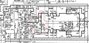
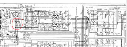
I'd say that a diode is an amplified transistor set at maximum current gain...it depends on the VAS trasistors to keep the current constant through them and the diodes will keep the refference for them watching the heatsink temperature...as for linearity...just look at the schematics above...Yes, if you look at a Vbe multiplier bias, it is in fact an 'amplified diode'. If you go to discrete diodes, it is much harder to set the correct thermal response with regards to the desired Re.
Shunt trimmer in parallel to the diodes is quite non-linear.
There's a good reason why Vbe bias circuits are almost always used.
Jan
Replies strongly support the use of a VBE multiplier. I posted this tbread because I have a serious bias instability issue. The series light bulb test indicates there is quiescent current instability with quite appreciable levels. Both amplifier modules use 220 Ohm cheap plastic presets. I suspect these cheap pots have bad slider contacts causing the bias to suddenly change causing the quiescent current to jump to unpredictable values. The VBE transistors are BD135 types.
Suggestions for better tests are appreciated.
Suggestions for better tests are appreciated.
Both amplifier modules use 220 Ohm cheap plastic presets. I suspect these cheap pots have bad slider contacts causing the bias to suddenly change causing the quiescent current to jump to unpredictable values.
Very, very unlikely that both fail the same way. Cheap does not necessarily mean bad.
Anyway, it's a no brainer to replace with another type to check, it doesn't have to be exactly 220 ohms.
Jan
A classic diodes+pot configuration is the original Dan Meyer Tiger amp. There's a schematic if you scroll down a bit here- https://www.diyaudio.com/community/threads/swtpc-universal-tiger-rebuild-for-analysis.344966/ My experience is, over time, pots are way more prone to failure than diodes or transistors. IMO, the pot should always be shunted so amp current is limited if the pot goes open. Sound-wise, I think either multiplier or diodes can work well, especially if you can find some old 1N3754 metal case diodes or similar to get good coupling.
That means diodes can do the job satisfactorily. What diodes can I use apart from metal cased rectifier bridges? An underbiasing chain of two diodes in series plus a low resistance pot should do the job.my replies don't support vbe multipliers for high power amplifiers at all..
Some rectifier diodes have thick wires which should be good conductors of heat if kept short. Two such diodes can be soldered to a copper plate which is then mounted to a heatsink for temperature sensing.
Last edited:
That is quite unrealistic if we are speaking of power transistors..Sure, I've used three diodes in series as a bias spreader. This gives an output stage bias current of
Iemitter = [ (3 * Vdiode) - (2 * Vbe) ] / (2 * Remitter)
Simply vary Remitter until you get the desired output stage bias current. Easy!
If you use TO-220 packaged diodes, you can mount them on the heatsink near the output transistors.
Re is selected to offer some thermal stability , to make multiple transistors share current evenly and even to sample current to trigger short protection, and as low value as possible, hence the typical 0.22 0.33 up to 0.47 ohm values chosen.
It is NOT a Bias adjustment system by any means and nobody ever used them for that.
The proper Bias system is to control applied Vbe , to make it temperature sensitive, and if possible: adjustable.
The problem with plain diode biasing is that it´s adjustable in "1 diode" steps (duh) while Vbe multipliers allow for fine adjustment to any value.
Diode bias adjustments are quite crude by comparison.
To do diode bias arrangements correctly, you need AREA scaling in the diodes to set the current. Easy in an IC, hard with off the shelf packaged parts. That’s the missing knob. A series resistor to add voltage drop or parallel resistor to trim the diode current down will work, but either is a kluge. When I do individual diode bias (to compensate separate transistors and heat sinks) I still put a vbe multiplier in series to take up the slack.
Most members seem to prefer a VEB multiplier for its ability of fine adjustment. However, the latter depends on using a variable resistance. As I strongly suspect in my case it is the pot failing, I would like to know what presets are used which offer the kind of reliability required by amplifiers.
- Home
- Amplifiers
- Solid State
- Diodes and VBE multipliers.