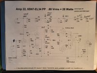
I recently built an EL-34 PP amplifier. When I did the initial power up / testing I hooked up 8R test loads to the speaker jacks but forgot to short the input jacks.
The B+ was down to 350V and EL-34’s where drawing about 90 mA
One I realized the open input jacks where the issue the B+ was 400V and the EL-34’s where drawing 35mA (as designed)
I have a 220K resistor across the input jack(s) and a 1K grid stopper on the 6SN7.
Why does this happen?
Is this unique to PP amps with Feedback? I never noticed this before on SE amps.
Is there a way to prevent this? (Other than shorting the inputs)
Yes, there is high level oscillation. Use shorting plugs in both inputs, as well as a resistor load.
Reversing output transformer connections will cause this.
Make sure the amplifier is stable with and without shorting plugs, before connecting speakers.
No amplifier should ever do this. After all, audio cables can come loose or open circuit.
Have you done an analysis of the circuit pole locations? Post the schematic.
Last edited:
Might try sticking a small capacitor like 50-100pf across the input and see if the power consumption changes.
There is no compensation network to set a dominant pole. This virtually ensures instability.
Add a series RC network across R10. As a guess, start with 3k in series with 470pF, and check the response.
Did your SE amplifiers have global NFB like this one?
Add a series RC network across R10. As a guess, start with 3k in series with 470pF, and check the response.
Did your SE amplifiers have global NFB like this one?

High input impedance and high open loop gain at HF, 22pF to ground on input and dominant pole needed across R10. You will also find the grids of the EL34's go more negative than the bias voltage when this happens. Exactly what rayma says.
As rayma says, probably also a capacitor across R14. When you apply feedback, you must expect to need to check and tweak stability on a square wave.
If you disconnect the FB it happen again with input open?One I realized the open input jacks where the issue the B+ was 400V and the EL-34’s where drawing 35mA (as designed)
Walter
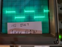
I only had 2 capacitors for testing, 33pF and 1nF
This is what I found using the parts I have.
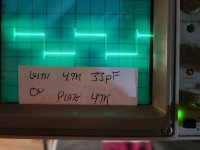
Adding 33pF across the input jacks reduced the no-load voltage at the EL34's cathode from 560mV to 510mV (goal is around 350mV)
Adding 4.7K and 33pF across R10 (input driver plate resistor) didn't help.
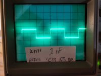
Adding 1nF across R14 (FB resistor) seems to have fixed the problem and improved the output (see pics)
So we fixed the original issue! Thank You All for the help!
I'm not done experimenting with this. Next time I place an order for parts I'll buy some capacitors for testing.
Most of the classic PP amps do have the R and C across the input drivers plate resistor, so I want to give this one more test.
This is what I found using the parts I have.
Adding 33pF across the input jacks reduced the no-load voltage at the EL34's cathode from 560mV to 510mV (goal is around 350mV)
Adding 4.7K and 33pF across R10 (input driver plate resistor) didn't help.
Adding 1nF across R14 (FB resistor) seems to have fixed the problem and improved the output (see pics)
So we fixed the original issue! Thank You All for the help!
I'm not done experimenting with this. Next time I place an order for parts I'll buy some capacitors for testing.
Most of the classic PP amps do have the R and C across the input drivers plate resistor, so I want to give this one more test.
Attachments
- Home
- Amplifiers
- Tubes / Valves
- Why do amps draw high current if the input jacks are open?