Unknown input voltage for PSU board on amp

I have an old Pioneer A-656 Stereo amplifier and it has a busted main transformer, all I kneed to know is what would the voltage be of the secondary windings?
I have a powersuppy that may work.
I'm assuming that the secondary is about 70vac
I have the schematics for the A-656 but the Australian one is not listed which I think all of the variations are the same execpt mine has the voltage selector, which shouldn't matter what voltage you select the secondary outputs the same?
Just need to know the output voltage, 2 wires off transformer numbered 45 and 44
Thanks guys
pioneer a656 psu.png

Class D type 2 driver board issue

It's a type 2 class D amplifier.

I've rebuild the whole driver board. New transistors, new caps, new ic, new diodes.
Even with no output mosfets in at the mainboard, the high side parallel emitter follower pair on the driver board are getting scorching hot in seconds and destroyed. No issues at the low side.
I've noticed also the cap in the red circle is getting bulged every time i power up the amp. I'm using 35v 47uf low esr cap, and there should not be so much voltage across it so it would bulge.
Driver Board Pin-Out are as they should be comparing it to the Perry's Manual.
With the driver board out, rail voltages, +-15, everything looks fine, i do have the proper sinewave at the +In:Audio input to the driver board.
I haven't changed only the ZD6, as I don't know what it is, but it measures just fine.
Any ideas where to look ?

Attachments

  • 123456.jpg
    123456.jpg
    112.8 KB · Views: 144

Ariston QDeck replacement motor

I have a Ariston Qdeck with a 12V motor that is toast due to my father using a AC adapter for it...
So, trying to find a spare is not going well, the motor has the marking SHR2R - 50-8Y11B, and I cannot find anything regarding this motor, no specs nothing. If anyone has any info on this it would be most appreciated!

I may be able to fit some replacement motor I guess, possibly with som DIY addings as neccessary. But for starters I need to find out what rpm the previous engine was running at.
The pulley is 5mm, and the turntable belt wheel is 180 mm. This calculator would suggest the motor speed rpm is 1188 for a 33 rpm output.
http://mgfic.com/rpm_calc.asp

USAmps USA100?

GE folks,
A friend passed on this unit to the shop, can’t seem to find any info on the web for it. It has USA100 REV05 printed on the underside. The few models/pics I saw of the USA100 don’t have dual RCAs and have two potentiometers.

I cleaned it up and populated a few parts in the pre section, injected +/-12v and I have a clean sinewave throughout the preamp section.

The pcb uses transistors for switching, small signal -A06 and -TIP35 for the higher current.
Again I populated a few parts and powered up but it doesn’t switch.

Anyone got info on this pcb?

Attachments

  • IMG_1699.jpeg
    IMG_1699.jpeg
    830.7 KB · Views: 99
  • IMG_1706.jpeg
    IMG_1706.jpeg
    581.8 KB · Views: 98
  • IMG_1700.jpeg
    IMG_1700.jpeg
    620.7 KB · Views: 102

  • Locked
For Sale Schade Common Gate (SCG) Preamp

Clearing some more stuff and the SCG full built preamp needs to go. Made with very high quality parts from Mouser, Parts-express and per the original design. The Antek toroidal (AS-05T120 - 50VA 120V TRANSFORMER) too is included in the sale. It is built to the original schematic from this thread by Rahul - https://www.diyaudio.com/community/threads/schade-common-gate-scg-preamp.380487/ with no modifications. I had this in a case but repurposing hence case is not included. Expecting $300 plus shipping in continental US only.

IMG-9861.jpg

IMG-9860.jpg

IMG-9858.jpg
  • Like
Reactions: ra7

For Sale SissySIT amp

I have 8 amps…, I have to to let this beauty go

500va toroidy trafo 230Vac
Teabag PSU board
Thf51 matched
400 deep amp 3U modushop
Cinemag CMOQ-4 high nickel trafos
Sounds great

Since I build the SIT-3X this amp gets less usage, but sounds actually equal
Hope It finds a good home
Open to acceptable offers, or a nice Fender Stratocaster to swap😉

Attachments

  • IMG_0596.jpeg
    IMG_0596.jpeg
    408 KB · Views: 216
  • IMG_0597.jpeg
    IMG_0597.jpeg
    466.3 KB · Views: 237
  • IMG_0598.jpeg
    IMG_0598.jpeg
    589 KB · Views: 257
  • IMG_0599.jpeg
    IMG_0599.jpeg
    473.3 KB · Views: 261
  • IMG_0600.jpeg
    IMG_0600.jpeg
    494.6 KB · Views: 238
  • IMG_0601.jpeg
    IMG_0601.jpeg
    510.5 KB · Views: 227
  • IMG_0605.jpeg
    IMG_0605.jpeg
    393.3 KB · Views: 227

Open Baffle - first project

I've been using Zu speakers for about three years, and they've opened my eyes to the beauty of high efficiency, dynamic speakers, and full range drivers. With help from this board, I built an Aleph J to run them. But...I'm looking for more soundstage and imaging than the Zu's provide. I was watching Steve Guttenberg's review of the Pure Audio Project duos and what he describes is I think, maybe, the sound I'm after. Plus, open baffles look easy enough to build with tools I have...no cabinet maker here! So...if I eventually wanted to work up to a PAP type clone, where should I start? What's a simple way to get a taste?

TB3/1000 is alive ! ("European 833A")

Good evening DIYaudio,

after constructing the 833A-amplifiers (see the thread "where are the 833 amps"; i've included enough pictures and text) which works great i found a whole bunch of old European transmitting triodes.

Philips TB 3/1000

Although the filament is somewhat different to the 833A (12 V / 8 A instead of 10 V / 10 A) the other characteristics are quite similar.

So i changed the 833A-amps to take the TB 3/1000. Why: because the TB 3/1000 is VERY neatly made. Not like the 833A where the plate simply hangs on the top-connector. No...with the TB 3/1000 the structure is made from bottom up. And any expansion through the heat is being taken care by letting the plate slide on glass rods !

See pictures......it works.

And soundwise.....after 5 hours of playing......musical delight.

I'll add some pictures.
The first a comparison picture of a 833A and a TB 3/1000.

Regards,
Reinout

Attachments

  • img_3004.jpg
    img_3004.jpg
    72 KB · Views: 4,099

Good grief PC packed up, a major disaster

Bought a new motherboard and cpu for my PC.
Had it 2 weeks it has died.
I really hadnt realised how much I use it or need it for home and work.
Having to try and use an old slow laptop in the meantime.
Took me half a day to download software to access the internet and email etc etc.
It really is dreadfully slow.
I need a back up desktop pc rather than a laptop.
First time in 30 years I have had a PC die on me despite building them all myself.
Tried a new power supply but still dead.

Today tried to program a PIC microcontroller.
Too 2 hours to download MPLAB X and get it running.
Then project file was empty and so was code file.
Turns out my flash drive is playing up.
The files are there but empty !
So need to bin it and buy a decent one.

Just to add to my problems the laptop turns it self off after a while.
Looked at power settings and they are fine.
I suspect its getting hot but fan isnt always going fast when it powers off.

Will appreciate my desktop pc more in the future.

For Sale Stepped Attenuator with RC and Display

SOLD
50K Stepped attenuator with remote control and display.
128 steps shunt attenuator. Resistors are a mix of Dale brown and blue high quality ones.
Just supply 6.5 to 7Vdc and it works as it should.
Simple and straightforward.

Hooked them up to test and they worked perfectly.
Was then placed into their boxes and stored.
Decided that I may not want to build another preamp.

58USD shipped.
Paypal Family & Friends only please.
Thank you.

LTP with Plate Chokes (line stage)

I've been thinking of building a 6SN7 LTP for a balanced input line stage using a choke as the plate load. I haven't seen much discussion of this approach. Anyone tried it?

What I'm considering is a Lundahl LL1667 which has two windings, one for each plate. I plan to use LED biasing, setting the bias point around 7ma per triode. Lundahl indicates that this choke is available with different air gaps to increase inductance for lower DC current. I'm hoping I can get up to 200H per winding based on my DC current requirements.

Based on simulations, this will start to roll off below about 200 Hz, but it's only down a small amount. I have a separate SS line stage for my subwoofer outputs which crossover to my mains at about 180Hz, so I think the low-frequency roll-off shouldn't be a problem. Anything else I should worry about?

The LTP plates will DC couple to a balanced mosfet source follower stage, so the next stage load will be negligible (except for the modest capacitive load).

I'm also open to other tube suggestions. I am thinking about the 6SN7 because I've heard that the new-production Linlai Global Elite tubes sound quite nice and I like the idea of being able to get new tubes.

For Sale Brand New TS400-4 15" Subwoofer - $200.00

Brand new TS400 15" 4 Ohm subwoofer with brand new Hypex DS8.0 800 watt plate amplifier. Sold together only. $250.00 - offers not considered. Local lower mainland Vancouver area pick-up only. Must be picked up by Saturday, January 6th at 6:00 p.m.. They both go to the landfill the following morning if unsold. I gotta move and can't wait longer.
JH

Fender Venue PA intermittent explosively-loud sound

Hi everyone... I have a Fender Passport Venue PA system, and it has been acting very strangely. It works perfectly when it's working, but then occasionally just "shorts out" or something, and just creates the loudest most shocking sound I've ever heard. Sometimes the "Protect" red light comes off and on, but that doesn't seem to 100% correlate with the sound issue. It can work just fine for a while, and then BRRRRRRRRRR. And it'll do it even if there's no inputs plugged in. And the "Protect" light sometimes comes on even if no speakers are plugged in.
Any ideas? Transistor? I'm not an electronics guy so I'm trying to gauge whether it's worth taking it in for repair, or if I should just sell it for parts. And I have no clue what these kind of repairs might run for. I called Guitar Center, they said all the local places around me are seriously backed up, so might be a lost cause anyways. But I still want to hear what folks think.
Thanks!

For Sale Copper Foil Tape

Hello All,

I have three never used rolls of copper foil tape intended for EMI/RFI shielding (see attached photo and data sheet). The tape is 1.75” wide, and about 36 yards long. Each roll weights about 1.5 pounds. These were purchased back in the late 1980’s. I just tested the adhesive on a roll I have been using low these many years, and as far as I can tell, it is as good as when originally purchased. I am selling these for $25.00 each plus postage, continental US only please. If you are interested please pm me with your e-mail address.

Cheers,
ceulrich

Attachments

  • Photo.jpeg
    Photo.jpeg
    322.4 KB · Views: 118
  • Data Sheet.png
    Data Sheet.png
    276.8 KB · Views: 113

Adcom GFA-565 rebuild / upgrade issue

Hi.

Got a pair of monoblocks from Advom that had issues when i bought them , and after some research i found that the main reason they fail is due to leaky capacitors on input board.
I opted to order new boards fom Hoppes with matched transistors , and then built / populated the rest on my own.

First amp had an offset of - 166mv , and after some reading on hoppes brain notification notes i found that the input board i built was working as intended.
Dc servo was well within specs along with pin 3 and 4 , so the issue was likely to be downstream.
Took out the output assembly where i checked all components , and only found 2 resistors to be drifted slightly....one that was 8.5 ohm (should be 7.5ohm) , and one that was 66 ohm (should be 68 ohm).
Changed the 2 resistors , cleaned it up and put it together...worked perfectly now with dc offset around single digits millivolts 🧐.

Did not really feel i found the issue on that 🤷

On the next monoblock i powered up slowly with dimbulb / variac (did same on first monoblock) , and had dmm on testpins looking for bias current and dc offset as i increased.
Seeing bias current but also alot more dc offset than the first amp.
Tried with full current on dimbulb to see how mutch offset , and it was - 3.2v.
Pin 3 and pin 4 on input board show correct voltages along with dc servo current.

Took apart the output assembly on this amp aswell ,.and found 2 resistors (same as first amp) to be slightly off and changed them.
Seem one or more of the output transistors is weaker than specs suggest (2sd424) , having hfe in the thirtys (hfe 34).
Could some weaker transistors be the reason of the offset i am seeing?
Datasheet say minimum hfe of 40

Attachments

  • IMG_20230714_170757.jpg
    IMG_20230714_170757.jpg
    397.2 KB · Views: 152
  • IMG_20230705_170834.jpg
    IMG_20230705_170834.jpg
    610.5 KB · Views: 172

Limiting Linux output volume 'Reliably'

I'm running Debian in a virtual machine, with a passthrough to a USB port, playing to an audio gadget as the output device. To avoid clipping (regardless of what application is playing sound), I've set Debian's 'maximum-volume' slider to 50%. The output-volume slider then correctly says 50% as its maximum setting. It mostly works well... but sadly isn't proving trustworthy. Glitches cause Debian to forget about the 50% limit (even though the output slider still claims that is max) and I get full volume output. I have my amps set to assume 50% at max, so that is quite loud!

Unfortunately I'm not very experienced with Linux yet, end even less so with its audio chain. Is there a method of setting the maximum output level such that Debian won't overlook it? Perhaps on a similar note, it would also be handy if there was a way to stop Debian swapping to other output cards, when the default audio gadget is temporarily absent?

Thanks,
Kev

Help with slight hum from Adcom GFA-2535

Hoping I can get some help with a faint hum that's coming from one of my Adcom amps. I'm currently using a GFP-555 preamp to drive three Adcom amps (GFA-545II, GFA-555II, and GFA-2535). Everything is being powered through a pair of Adcom ACE-515 AC enhancers plugged into separate outlets (on the same circuit though). I'm splitting my norm and lab outputs with Amazon Basics heavy shielded RCA splitters and cables. The 545II and 555II have zero hum.

What I've noticed on the 2535's hum is that it doesn't change as you increase the volume on the preamp. It's a constant hum. Thing is, as soon as I unplug the RCAs from either side, it's gone. This made me initially think it was my preamp, but even when plugging my bluetooth receiver directly into the 2535 it produces the same hum. It's almost as if there is something coming in on the RCAs that is causing this.

I've tried various cables, different sources, etc. No change. I have eliminated most other devices on this circuit, save a couple deep freezers that I can't move off this circuit just yet. I even removed the coax coming into my TV to ensure that was not the culprit. There are also no fluorescent lights or dimmers on this circuit.

The most recent thing I've done to try and eliminate this is connect the grounding posts of my ACE units together, along with the post on my GFP-555 (following the ACE-515's manual). No change.

Any help is greatly appreciated. While I've read this hum isn't "bad", and it's only noticeable when you're close to the speakers being driven by the 2535; it's quite annoying.

-Dibbers

Mediaworks ADAU1467 eval with DSigma Studio

Dear every body,
I just receive eval board mediaworks with ADAU1467.
I seen many thing for my project in Delta sigma studio.
Now with a very basic design i'm trying to load program with TinySine USBI. But something is missing.
My project (to begin) is to use the SPDIF input (with a 44,1KHz signal) and transfert it directly to the analog output1 channel 0/1 as below.
But i'm unable to confirm that the program is inside the DSP and then the systeme is not working...
Maybe some one can help me to start this first step of project?

Thank you...

1697812461262.png


1697812280655.png


1697812383643.png


1697812545821.png


1697812597575.png


1697812623622.png

High voltages in Elekit TU8600S

Hi, A couple of months ago I built the elekit tu8600s. The amp worked well for a while but then suddenly one of my 300B’s stopped working. After a while it worked again but then after some weeks it didn’t work again for a little while, this repeated a couple of times untill ik broke down for good. I then looked inside the amp and checked the voltages and found that tp 13,14, 23 an 24 are double what they should be. I checked if all the parts where in the wrong place and redid some soldering, but I can’t seem to find my mistake. Is there anyone who had a similar problem and can help me?

Camilladsp on Radxa rock 5b?

Continue here from the camilladsp thread starting on post 4333 due to way too much off topic:

I am trying to install camilladsp on this board. The camilladsp install went ok until I came to the loopback interface. There was no snd-aloop module in the kernel.

Bash:
 This is a boot script for U-Boot
#
# Recompile with:
# mkimage -A arm64 -O linux -T script -C none -n "Boot Script" -d boot.cmd boot.scr

setenv load_addr "0x9000000"
setenv overlay_error "false"

echo "Boot script loaded from ${devtype} ${devnum}"

if test -e ${devtype} ${devnum}:${distro_bootpart} /ubuntuEnv.txt; then
        load ${devtype} ${devnum}:${distro_bootpart} ${load_addr} /ubuntuEnv.txt
        env import -t ${load_addr} ${filesize}
fi

load ${devtype} ${devnum}:${distro_bootpart} ${fdt_addr_r} /dtbs/${fdtfile}
fdt addr ${fdt_addr_r} && fdt resize 0x10000

for overlay_file in ${overlays}; do
    if load ${devtype} ${devnum}:${distro_bootpart} ${fdtoverlay_addr_r} /dtbs/overlays/${overlay_prefix}-${overlay_file}.dtbo; then
        echo "Applying device tree overlay: /dtbs/overlays/${overlay_prefix}-${overlay_file}.dtbo"
        fdt apply ${fdtoverlay_addr_r} || setenv overlay_error "true"
    elif load ${devtype} ${devnum}:${distro_bootpart} ${fdtoverlay_addr_r} /dtbs/overlays/${overlay_file}.dtbo; then
        echo "Applying device tree overlay: /dtbs/overlays/${overlay_file}.dtbo"
        fdt apply ${fdtoverlay_addr_r} || setenv overlay_error "true"
    elif load ${devtype} ${devnum}:${distro_bootpart} ${fdtoverlay_addr_r} /dtbs/overlays/rk3588-${overlay_file}.dtbo; then
        echo "Applying device tree overlay: /dtbs/overlays/rk3588-${overlay_file}.dtbo"
        fdt apply ${fdtoverlay_addr_r} || setenv overlay_error "true"
    fi
done
if test "${overlay_error}" = "true"; then
    echo "Error applying device tree overlays, restoring original device tree"
    load ${devtype} ${devnum}:${distro_bootpart} ${fdt_addr_r} /dtbs/${fdtfile}
fi

load ${devtype} ${devnum}:${distro_bootpart} ${kernel_addr_r} /vmlinuz
load ${devtype} ${devnum}:${distro_bootpart} ${ramdisk_addr_r} /initrd.img

booti ${kernel_addr_r} ${ramdisk_addr_r}:${filesize} ${fdt_addr_r}

boot.scr

Bash:
^E^YVM^A^[Ze^Cw�^@^@^Gc^@^@^@^@^@^@^@^@^Q�:K^E^V^F^@Boot Script^@^@^@^@^@^@^@^@^@^@^@^@^@^@^@^@^@^@^@^@^@^@^@^G[^@^@^@^@# This is a >
#
# Recompile with:
# mkimage -A arm64 -O linux -T script -C none -n "Boot Script" -d boot.cmd boot.scr

setenv load_addr "0x9000000"
setenv overlay_error "false"

echo "Boot script loaded from ${devtype} ${devnum}"

if test -e ${devtype} ${devnum}:${distro_bootpart} /ubuntuEnv.txt; then
        load ${devtype} ${devnum}:${distro_bootpart} ${load_addr} /ubuntuEnv.txt
        env import -t ${load_addr} ${filesize}
fi

load ${devtype} ${devnum}:${distro_bootpart} ${fdt_addr_r} /dtbs/${fdtfile}
fdt addr ${fdt_addr_r} && fdt resize 0x10000

for overlay_file in ${overlays}; do
    if load ${devtype} ${devnum}:${distro_bootpart} ${fdtoverlay_addr_r} /dtbs/overlays/${overlay_prefix}-${overlay_file}.dtbo; then
        echo "Applying device tree overlay: /dtbs/overlays/${overlay_prefix}-${overlay_file}.dtbo"
        fdt apply ${fdtoverlay_addr_r} || setenv overlay_error "true"
    elif load ${devtype} ${devnum}:${distro_bootpart} ${fdtoverlay_addr_r} /dtbs/overlays/${overlay_file}.dtbo; then
        echo "Applying device tree overlay: /dtbs/overlays/${overlay_file}.dtbo"
        fdt apply ${fdtoverlay_addr_r} || setenv overlay_error "true"
    elif load ${devtype} ${devnum}:${distro_bootpart} ${fdtoverlay_addr_r} /dtbs/overlays/rk3588-${overlay_file}.dtbo; then
        echo "Applying device tree overlay: /dtbs/overlays/rk3588-${overlay_file}.dtbo"
        fdt apply ${fdtoverlay_addr_r} || setenv overlay_error "true"
    fi
done
if test "${overlay_error}" = "true"; then
    echo "Error applying device tree overlays, restoring original device tree"
    load ${devtype} ${devnum}:${distro_bootpart} ${fdt_addr_r} /dtbs/${fdtfile}
fi

load ${devtype} ${devnum}:${distro_bootpart} ${kernel_addr_r} /vmlinuz
load ${devtype} ${devnum}:${distro_bootpart} ${ramdisk_addr_r} /initrd.img

booti ${kernel_addr_r} ${ramdisk_addr_r}:${filesize} ${fdt_addr_r}

How do we use DSP to compensate for higher than optimum Qtc in subwoofers?

I have a pair of 12" woofers I'd like to use with some small (1.45ft3) cubic enclosures on hand. The recommended
enclosure volume was ~3ft3 for a low (38Hz) Fc and Qtc of ~0.7. The small cubes seem to give an Fc of 49Hz and Qtc is~1.1 .

These woofers are to supplement the lower base of my 8" towers, which have limited output below 80Hz.

I have read that using DSP, one can 'fix' the smaller system to act like the larger one at resonance and cutoff. How does this work
and how would I accomplish it with my P.E. Dayton SPA250dsp plate amp (anyone doing this already)?

Also, would the resulting equalized woofer system be as well damped as one in a 3ft3 box, Qtc=0.7?

Thanks for any advice(other than box redesign) ;-)

-C

A tweeter that is way too sensitive?

I was forced to put a 33 Ohm resistor in series with my tweeter in a 2-way speaker. (Same arrangement on both L and R speakers in a stereo pair.)
Otherwise, the tweeter was dominating like crazy.
The tweeter is 4 Ohm in resistance. So it seems I'm running it at 8.5% capacity (!) This is unbelievable to me, losing over 90% of tweeter efficiency to balance out the sound.
How normal / usual is this?

Gimbal BLDC motors for direct drive?

Has anyone experimented with a gimbal bldc motor for a direct drive turntable?

My belt drive turntable DIY experiment is working well. I am finding different belt materials have huge impact on speed stability/ wow and flutter. (Silicone belts are terrible for this btw. Standard butyl is ok, but needs a second pulley opposite the motor to reduce lateral stress on the platter. My next experiment there will be with surgical silk for a custom belt.)

But I would like to compare it to a direct drive platter to see if there is further improvement. I ordered an 11pole pair hollow shaft gimbal motor. I have several FOC/sinusoidal /vector controllers to play with to see how well I can spin ot at 33.33 with a weighted platter.

Using a capacitance multiplier to suppress interference from switching power supply.

I would like to ask whether a capacitance multiplier circuit can suppress interference, more precisely, ringing, from a switching power supply. The latter is a laptop charger power supply which supplies power to a laptop which I use for a USB oscilloscope. Interference signals are showing superposed on whatever signal I happen to examine and view. These are in the form of decaying ringing. Their effect also prevents whatever signals are viewed to lock into view.

Transformer leads

This happens again and again. Simple question. What leads are to be connected for a dual primary transformer if the polarity of the windings is not stated. This is an R-core transformer if that makes a difference. The transformer clearly states '115 volts Black-Red and Grey-Orange' are the 4 wires of the primaries, but there is no indication as to what leads need to be connected together for both primaries to be connected in parallel. I know that if I connect them out of phase, I am screwed. Here is a photo. To be clear, my home is 120 VAC and not 220 VAC.

PA160001_01.JPG

MiniRef Schematic and PCB layout

This is a first-pass attempt at building a scaled-down, value-oriented version of a nested gainclone similar to the Mauro Penasa MyRef design. It differs from the MyRef RevC in several ways:

1) LM1875 chipamp as the Howland current pump offers more component flexibility - can be interchanged with TDA2040, 2050, etc.

2) Lower output power of 20W + 20W makes it suitable for bookshelf and HT setups.

3) Two channels/board to reduce overall system costs. The board is only ~15% larger than a single MyRef RevC version 1.3 monoblock.

4) Op-amp flexibility - it will work with numerous commodity (NE5532, etc.) and premium opamps (LM4562, OPA2134, etc.) for the outer voltage-feedback loop, with slight changes in compensation in some cases.

5) Outer loop uses Walt Jung's nested schema, which differs slightly from the MyRef.

6) Compensation schema is much simpler, with a single modified DeBoo integrator per channel, greatly reducing the component count of premium capacitors compared to the RevC.

7) Speaker protection circuit is identical to the MyRef RevA 2-channel schematic.

8) Shared rectifier and PSU caps to reduce board area and costs.

I'm calling it the MyRef Mini because of its close similarity to Mauro's MyRef series. It still needs to be built and validated, but I expect it to be comparable to or better than the MyRef Rev A in audible sonics (with the components shown in the schematic). In audible sonics, it should comfortably crush the Yuanjing and similar EBay gainclones based on the LM3886, LM1875, LM4766, TDA7294, etc., at a slightly higher price point for a 2-channel board.

Here are the exported images of the Schematic and Board Layout (warning: although completed, this is only a first-pass attempt and may have undiscovered errors in both the schematic and layout). The dimensions of the PCB are about 5.5 x 3.2 inches. The BoM should be sub-$50 for the PCB and all the components on the PCB. If there's sufficient interest, I'll eventually have a small batch of bare PCBs fabricated and offered here.

Attachments

  • mini_1_0_sch.png
    mini_1_0_sch.png
    115.8 KB · Views: 10,240
  • mini_1_0_pcb.png
    mini_1_0_pcb.png
    150.2 KB · Views: 9,702

Here is another clever circuit published by "The Master", but....

This is the article:
https://www.edn.com/adjust-op-amp-gain-from-30-db-to-60-db-with-one-linear-pot/
Very nice, as usual, but something bothers me though: Stephen recommends the use of low excess noise resistors in the feedback divider, but I don't see why: these resistors do not see any static bias, except that caused by the input current and offset of the OP37, which are normally minuscule.
The signal itself, if large enough, could cause excess noise on high-amplitude excursions, but it should remain moderate and drowned in a much larger signal.
It would result in a noise component having its enveloppe modulated at twice the signal frequency, thus excess noise from a frequency-domain perspective since the modulation should change nothing there, and maybe a kind of "breathing effect" for large, VLF signals in the time-domain.
To summarize, poor resistors would not affect the noise floor of the system (it would be quiet), but it could degrade the THD+noise distortion figure, but I don't think it would be relevant because of the low amplitude, even for carbon-film resistors, and because the noise would be random, uncorrelated to the signals processed.
Did I miss something? Can a poor resistor have a hotter virtual temperature than its physical temperature?
  • Like
Reactions: jackinnj

Is it possible to modify this DAC?

I have an a/d/s/ DA20e. It still works fine. Today, I have opened the top cover to check the unit by sight. I found the condition is like new. I also found there’s a vacant socket labeled 9V, as shown in the red circle on attached. I wonder is it possible to modify this DAC? There’s very little info about this DAC. Has anyone ever experienced?

Attachments

  • 05577909-7B81-45B1-A071-E718F2C9FFA1.jpeg
    05577909-7B81-45B1-A071-E718F2C9FFA1.jpeg
    98.8 KB · Views: 228

Papa Rusa (headphone amp) power supply design

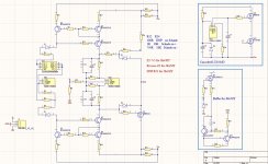
I've been using PSUD over the years but still some gaps, if someone can provide answers or anything I need to learn, here is where I'm at with the unregulated supply for a Papa Rusa...

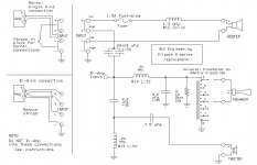
1) For the DCR of the transformer I measured the DCR of my secondary to be 67 ohms. Should I also add in the DCR of the primary? Or is this setting mean the DCR of the secondary only.

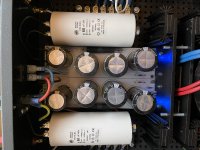
2) In the simulation below I went with the default 2 ohms for the capacitors. These will all be DC link capacitors, what would be a common resistance to use here for film caps instead of 2 ohms, (which I assume are electros)?

3) I want to test how "fast" my power supply can recover from a 5ma upward transient draw. I want it to be "fast" so using as little capacitance and resistance as possible. This PS will be for a parafeed headphone amp (Papa Rusa link below) so I dont think the draw will be bouncing around much as its only driving headphones not speakers. So thats why I only tested a 5ma jump from 60ma to 65ma. As you can see it recovers pretty fast to the lower voltage and with no "bounce" or thrashing around just the downward dip, at the 2 second mark. I experimented with more capacitance but it was slower and the waveform hilly. It recovers in .4 seconds. Did I do such a transient simulation properly, or is my thinking way off here? The PS comes to full voltage in .6 seconds as well. I'm assuming the bounce at the beginning is just inrush because using solid state rectifiers, it seems to settle in fast though. Maybe the speed has to do with using a choke too instead of a resistor after C1, because chokes hold magnetic energy I would think thats better than a resistor right?

4) I want the ripple under 3mv, as you can see it achieved 2.8mv. This headphone amp uses a plate CCS so that will scrub even more ripple. So I think I'm happy with compromising ripple against speed.

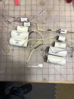
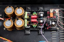
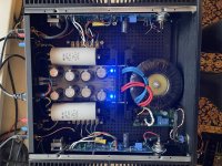
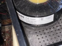
5) Also note, the first choke is a real choke Hammond 14 H; 75 ma; 429 ohm model. But the second choke is a MOSFET gyrator set to simulate 30 H at 30 ohms. This headphone amp calls for 275V B+ @ 60ma so I think I nailed it with getting 280V. This transformer gives me exactly 236 volts from my home mains.

6) I took advantage of the highish DCR of the first choke to go with a smaller C1, much smaller than this and the PS seemed not stiff enough, I experimented with the middle capacitor but found that 1uf in the middle gave the best transient timing, the third cap I experimented with judging ripple against speed and settled upon 50uf which keeps me out of using electrolytics, the final 1 ohm and 3uf stage will be doubled for left/right channels.

This has been fun trying to make a power supply with as little resistance and capacitance as possible competing ripple against transient speed, it was good PSUD practice.


5ma upward transient 60 to 65ma at 2 seconds (looks good to me but I'm a newby):


No bouncing around at 2s just what seems like a nice smooth drop.

1697924222895.png


Ripple of 2.8 mv achieved:
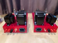
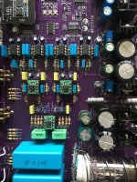
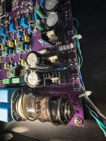
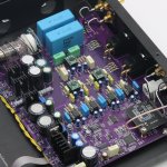
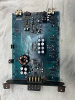
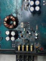
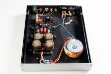

1697924347223.png


The project:

Papa Rusa

https://wtfamps.com/papa-rusa-headphone-amplifier/

1697924159396.png

help with Hickok 539a

I found this tube tester in mercaplace, it has some problems, one of them is damaged rheostat-potentiometer 200 ohm 25 w, which I already ordered, it also has 9 loose cables that go to the sockets attached photo, I have tried to read the diagrams but I have not been able to find the position of the cables, I know that most of them go to the noval socket, I am new to electronics hoobie and I am learning.
some information or photo of the 9 pin socket would be of great help.

Attachments

  • 20231021_130923[1].jpg
    20231021_130923[1].jpg
    472.9 KB · Views: 96
  • 20231021_130845[1].jpg
    20231021_130845[1].jpg
    563.7 KB · Views: 104

FS: EL84 Mono Blocks

This is a fantastic sounding Pair of EL84 Mono Blocks
They were Built by John Miller of Tomcat Audio
They use a pair of EL84 or Russian 6p14 and a single 12at7
Mundorf Power supply caps, Miflex copper input coupling caps
They are 22 watts in push pull. with Hammond Transformers
$950 local pickup in Huntersville,NC

Attachments

  • IMG_3974.JPG
    IMG_3974.JPG
    329.9 KB · Views: 271
  • IMG_3975.JPG
    IMG_3975.JPG
    379.7 KB · Views: 289
  • Like
Reactions: e_fortier

Any proven synergy designs with plans?

Hi all.
Im looking for plans to build from. Synergy tops for small to medium outside use. 130+db@1m(more is more), 90 degree horisontal would be nice and usable to 100ish Hz. For subs im planning a pair of Skhorn double 21”s. If somebody has the plans for these, id be gratefull for those also.

I know there are lots of builds around, but has anybody drawn any plans to build from?

Thanks

Sun Audio SV300BE voltage change to 120

Hello,

I’m interested in purchasing a prebuilt sun audio SV300BE from Japan. However the unit is 100v and I need a 120v for operation in the United States. Is it possible to convert the 100v to 120v without a separate step up (step down?) converter?

Is this a matter of swapping and soldering transformer wires? Or are the transformers themselves different? According to the sun audio website there are 3 versions: 100v, 120v and 240v which you must specify before ordering the kit. So I assume it is a whole different transformer. I hope I’m wrong.

The effect of box volume on loudspeaker output?

I get the basics but a debate on another thread regarding Sony SS-S9s has got me wondering about cabinet volume. Why does a driver need a certain cabinet volume and when does it need said volume?
They were discussing 2.5 systems which bring me back to an old question: A sub-woofer and woofer sharing the same air space in a ported cabinet. Some have suggested that all calculations be made on the mean value of the driver's T/S parameters - makes sense. But what happens at high power levels? When the woofer becomes affected by the sub's response to frequency it doesn't 'do'. Effectively offering passive radiation and robbing the port of input ?

Those 30v 3amp Dual "tracking" Power supplies..

Hi, can you please school me on today's plethora of these power supplies.. ?
Looks like clones of the Tektronics from some years ago.

Noisy ? good regulation, tracking, V droop with pulsed/ fast rise time loads, etc. ?

I am going to need one soon enough, though the Voltage and Current are under what I would prefer.
Currently have a feeler out to a local PS repair shop for an adjustable dual 50V 10A, but I probably wont be able to afford it.
As a mid-choice lets say a 36 - 38V 5A, Dual tracking adjustable bench supply would be great.

thanks very much for your advice!

Garage Sale ICs, OA, IGBT - All New and Originals

Hi All

For sale:

3 x MAX3223CPP+ Analog Devices
3 x MAX3322EEUP+ Analog Device

4 x SI9110DJ Vishay - Siliconix
1 x UA741HC Fairchild

2 x SG3524N Texas Instruments
5 x LM2675M-5.0-NOPB Texas Instruments
5 x LM2675M-12-NOPB Texas Instruments
5 x LM2675N-ADJ-NOPB Texas Instruments

100 x 4608X-101-104LF Bourns

1 x ICL7107CPL+ Analog Devices
1 x ICL7117CQH-TD+ Analog Devices
1 x ICL7126CPL+ Analog Devices

1 x MAX232CPE+ Analog Devices
1 x MAX691CPE+ Analog Devices
1 x MAX791CPE+ Analog Devices

Please PM.

Regards,
VS

IMG_2456.jpg

Attachments

  • IMG_2457.jpg
    IMG_2457.jpg
    162.1 KB · Views: 61
  • IMG_2458.jpg
    IMG_2458.jpg
    86.5 KB · Views: 80
  • IMG_2459.jpg
    IMG_2459.jpg
    102.8 KB · Views: 67
  • IMG_2460.jpg
    IMG_2460.jpg
    110.2 KB · Views: 68
  • IMG_2461.jpg
    IMG_2461.jpg
    108.9 KB · Views: 64
  • IMG_2462.jpg
    IMG_2462.jpg
    122.5 KB · Views: 62
  • IMG_2464.jpg
    IMG_2464.jpg
    108.5 KB · Views: 94
  • IMG_2465.jpg
    IMG_2465.jpg
    102.6 KB · Views: 84
  • IMG_2466.jpg
    IMG_2466.jpg
    82.3 KB · Views: 77
  • IMG_2468.jpg
    IMG_2468.jpg
    96.6 KB · Views: 78

Sony TC-K770es rewind issue

Hello Guys,

A few days ago i bought a Sony TC-K770es deck. Apparently it has been serviced not long time ago. I noticed that when rewinding, after several seconds it starts forwarding itself without any reasons, and keeps on forwarding. It looks like someone presses the FF button when rewinding. Does anyone have any idea what the problem is?

Thank you in advance!

Interesting new Jericho 2023 using Dayton

In the new issue of the German magazine Hobby Hifi (2-3/2023), mr Bernd Timmermanns offered an update to his Jericho horn, this time using the Dayton PS220-8 fullranger.
The measurements are promising. You can also see the effect of the correction filter. It looks like an interesting project.
The magazine has a 14 page detailed article including a step by step construction guide.

5B6A05EC-A96E-4AF2-A27C-C8F11CB03127.jpeg. 99777959-833B-4350-B08B-B4AD1E589F52.jpeg. 1D94E3A9-1F3E-453D-AFFD-3E7D32754E87.jpeg

For Sale Sonicap for Klappenburger Universal

I have a complete set of the recommended Sonicap Gen I poly caps (including recommended bypass caps) for building the Al Klappenburger Universal Crossover for Heritage series Klipsch speakers. If you are thinking of building that one very good crossover to service any of the Klipsch Heritage Series speakers, this is a huge first step. See images for the exact schematic and the caps you would be buying. $50 takes all.


Items sold: thank you.

Attachments

  • ALK UNIVERSAL copy 2 copy.jpg
    ALK UNIVERSAL copy 2 copy.jpg
    78.2 KB · Views: 152
  • IMG_4660.JPG
    IMG_4660.JPG
    414.7 KB · Views: 148
  • tempImagekZhEOi.gif
    tempImagekZhEOi.gif
    1.4 MB · Views: 149
  • tempImage5dRcIb.gif
    tempImage5dRcIb.gif
    1.4 MB · Views: 156

Using Triax cable to eliminate capacitance seen by a source such as an mm cartridge or tape head

I've just come across this concept and haven't seen any discussion of it or the theory involved. Apparently you "drive" the inner shield (somehow) to keep it at the same impedance as the source thereby eliminating any leakage current or capacitance seen by the source.

Any one provide any "light" or references on the subject? And how would you do this - what kind of driver and how should you CORRECTLY connect the cable on both ends. Make any sense to use in a preamp?

I urgently need help with the transistors SJ2517 and SJ2518

Hello,
I absolutely need data on the following transistors. SJ2517 / SJ2518
Does anyone have a data sheet, specifications and/or can tell me replacement types available from Distrelec, Mouser or others? Because MJ21193 / MJ21194 would fit (as claimed in another forum) I can only get them from Chinese dealers.
Thank you very much in advance and kind regards from Germany

For Sale Transcendent Sound Masterpiece 300B preamp

Sold

Transcendent Sound Masterpiece 300B preamp. Comes with a set of tubes that have around 100 hours on them. I used it in a secondary system that has moved to a home theater setup. The preamp sounds good to my ears. There is a slight hum that I can only notice if I turn off whatever is playing and put my ear 1-2" from the speakers (~88 db efficient). It never bothered me enough to chase it down.

Asking sold plus actual shipping charges

Ships in a box that is 21" x 18" x 13" from 54956

300b 2.jpg300b 1.jpg300b 3.jpg300b 4.jpg300b 5.jpg300b 6.JPEG

For Sale Markaudio CHP-70.2 new

A pair of never used never mounted CHP70.2 khaki.
Boxed and new. Price 50 Eur
Pickup by your courier at my address zip 27047 Italy. Post rates for pick up from European destinations are Better than if i ship. Of course i can ship if you prefer but it might costs 25-30 Eur probably.

Attachments

  • IMG20231011175952.jpg
    IMG20231011175952.jpg
    454.3 KB · Views: 88
  • IMG20231011180051.jpg
    IMG20231011180051.jpg
    366.5 KB · Views: 83

does anyone know what this diode equivalent is

have an old trio w41 tube amp that just smoked up (old capacitor died) but one of the diodes melted but i cant find any info on it online
trying to find the equivalent or close enough to replace it
has FR1 green dot dollar sign on it (pic attached)
)also have schematic if that will help
cheers

Attachments

  • IMG_20231021_223314_558.jpg
    IMG_20231021_223314_558.jpg
    355.1 KB · Views: 147
  • Trio-W41-1536x10402.png
    Trio-W41-1536x10402.png
    201.6 KB · Views: 146

Xiang Sheng DA5II tube and OPA mods help

Hi , guys , would be very grateful if you can help me to identify I/V opa place in this dac - there is 3x 2604AU op-amp ( green colour ) and
4x LME49720NA on the row
I wanted concentrate on the tube output - would guess that opa is for solid state output ? What would be the most effective sound wise opa upgrade - as I wanted to put Burson V6 for I/V place - could I get sonic benefit in other places ?

Regarding tube output - there is not enough plate voltage for 5670/396a/2c51c tubes to be used for optimum plate voltage - at the moment is around 77v - one option is to remove 150u 250v capacitor and voltage regulator L7806cv next to the tube and E13005 -2 transistor which could rise voltage to 120v ?
Very grateful if you can advice me . Val

Attachments

  • thumbnail_IMG_1021.jpg
    thumbnail_IMG_1021.jpg
    713.3 KB · Views: 90
  • thumbnail_IMG_1020.jpg
    thumbnail_IMG_1020.jpg
    662 KB · Views: 87
  • IMG_1329.jpeg
    IMG_1329.jpeg
    578.8 KB · Views: 87
  • thumbnail_IMG_1022.jpg
    thumbnail_IMG_1022.jpg
    642.1 KB · Views: 86
  • s-l1600.jpg
    s-l1600.jpg
    268.1 KB · Views: 124

Help Please, can 7 or 8 of these new tweeter/ Midrange planars be used in a Line Array?

Hello, I was over at Parts Express and saw these new Planar speaker drivers that are on Sale the model is GRS PT6816-8 8 inch Planar Slim Tweeters , their Frequency Response is 320 to 20,000hz , I am thinking of using 7 or 8 of them in a Line Array as Tweeters .... and maybe 7 or 8 of the GRS PT6825-8 8 inch Planar Mid//Tweeters as the Midranges which are on Sale too ....... I was wondering if the tweeters can be mounted close enough to each other to avoid any major Lobing issues? -


GRS PT6816-8 Tweeters
- https://www.parts-express.com/GRS-PT6816-8-8-Planar-Slim-Tweeter-8-Ohm-272-128

-
-                                           GRS - TWEETER.jpg


GRS PT6825-8 Tweeter/Midranges
- https://www.parts-express.com/GRS-PT6825-8-8-Planar-Mid-Tweeter-8-Ohm-272-126

-
-                                          GRS - MIDRANGE.jpg

Attachments

Free AD811 IV Boards

I have 3 spare AD811 IV empty boards as described here:
https://www.diyaudio.com/community/...s-input-nos-r-2r.354078/page-368#post-7451599

I have successfully built one:
https://www.diyaudio.com/community/...s-input-nos-r-2r.354078/page-372#post-7483361
https://www.diyaudio.com/community/...s-input-nos-r-2r.354078/page-372#post-7484982

I truly like the sound of this board with my Miro AD1862 DAC.

I would like to give away 3 spare empty boards (limited to 1 board per member) if it make sense for you to pay US$2 for regular letter mail for the board to be sent to you.
If you like to have tracking available, it would cost US$9 for the shipping as registered package.

Paypal as family and friends only please.

For Sale Ludef OPS with current mirrors (pooh with LU1014)

Hello,

Recently I built 4 of these amps and used them in a bridged configuration for a few months.
With these amps I mean only the output stage. To drive them you will need an adequate preamp able to deliver the entire voltage swing.

I tried both bridged and single ended and decided that I will remain with the se configuration meaning I will keep 2 amps and sell the other 2.


A pair was given away.

2nd pair is now sold.

Attachments

  • 63174A09-1337-438F-A1BC-61711E469B7C.jpeg
    63174A09-1337-438F-A1BC-61711E469B7C.jpeg
    263.1 KB · Views: 329
  • 3B9ECDC5-B507-4643-8FBD-C5837078A5FF.jpeg
    3B9ECDC5-B507-4643-8FBD-C5837078A5FF.jpeg
    75.5 KB · Views: 364
  • 9197F86A-55B0-49C5-BBAB-94E714732020.jpeg
    9197F86A-55B0-49C5-BBAB-94E714732020.jpeg
    772.2 KB · Views: 319
  • 7E07F129-CF7A-48B5-8B53-A1C8D39843DE.jpeg
    7E07F129-CF7A-48B5-8B53-A1C8D39843DE.jpeg
    640.1 KB · Views: 351

Technics SU-A700

I have an SU-A700 non MK2/ 3 with burned resistors R751, R752, R754 and R755. R753 and 756 have gotten hot as well but not burned like the others.

There is no sign of any other damage except for darkening of the board around these resistors.

As this amplifier uses bespoke Technics ICs and is rather difficult to get apart, requiring removal of the main ICs on the heatsink in order to access the solder side of the main board, can anybody with experience in this unit let me know if it is worth bothering with? I fear that as no other damage is visible, one of the ICs is to blame and I unfortunately can't power up the unit given the burned resistors.

Thel Negative low noise PSU

For sale a Thel-Germany low noise Psu up tu 10A and 100V.
Verry little use and top condition. Iv used this for negative bias voltage supply on my EL34 tube amp. But you can use this also for other project. Price would be 40 euro plus shipping 8,90 euro inside EU. Payment paypal for friends.

Attachments

  • IMG_20230327_105148.jpg
    IMG_20230327_105148.jpg
    410.3 KB · Views: 88
  • IMG_20230327_105215.jpg
    IMG_20230327_105215.jpg
    335.9 KB · Views: 92
  • IMG_20230327_105211.jpg
    IMG_20230327_105211.jpg
    352.1 KB · Views: 88
  • IMG_20230327_105152.jpg
    IMG_20230327_105152.jpg
    457.3 KB · Views: 86

Does anyone know what this 4-pin power terminal looks like?

I got the SPARK Houston MINI-1998.
However, in order to drive this amplifier, I have to supply power to the amplifier itself from a separate power supply unit.
The terminals on the power cable that supplies this power were unlike anything I had ever seen before.
I would like to know what this 4-pin, round terminal is and if it is possible to get the same one.
I would appreciate any help from you knowledgeable people.
Thank you in advance.

From Japan
20231020_012407.JPG

MEGURO MN-446A Noise Meter repairs

Hi,
Just wondering if someone might happen to have a Service Manual or schematics for the MEGURO MN-446A Noise Meter please?
I have one of these units and its developed an internal noise fault that is leading to erratic readings.

MN-446A_front.jpg

The new owners of MEGURO DENKI, Japan, no longer carry any information for historic MEGRUO products.
Thanks in advance.
A.

IMG_7225.JPG

IMG_7227-001.JPG

IMG_7229-001.JPG

IMG_7230-001.JPG
Projects by fanatics, for fanatics
Get answers and advice for everyone wanting to learn the art of audio.
Join the Community
507,797
Members
7,888,840
Messages

Filter

Forum Statistics

Threads
406,261
Messages
7,888,840
Members
507,797
Latest member
Moza