I have a pair of 12" woofers I'd like to use with some small (1.45ft3) cubic enclosures on hand. The recommended
enclosure volume was ~3ft3 for a low (38Hz) Fc and Qtc of ~0.7. The small cubes seem to give an Fc of 49Hz and Qtc is~1.1 .
These woofers are to supplement the lower base of my 8" towers, which have limited output below 80Hz.
I have read that using DSP, one can 'fix' the smaller system to act like the larger one at resonance and cutoff. How does this work
and how would I accomplish it with my P.E. Dayton SPA250dsp plate amp (anyone doing this already)?
Also, would the resulting equalized woofer system be as well damped as one in a 3ft3 box, Qtc=0.7?
Thanks for any advice(other than box redesign) ;-)
-C
Higher Qtc -> stronger resonance -> more bass....
Compensation: EQ -> limit the bass with a proper PEQ....
Its just that actually... the you have your room... its all a mess 🙂
Listen / measure in your sweet spot - turn the knobs...
The Dayton may have a "DSP" but I assume the Fo are fixed? Q is feed? Its quite limited tool really...
Good luck!
//
Compensation: EQ -> limit the bass with a proper PEQ....
Its just that actually... the you have your room... its all a mess 🙂
Listen / measure in your sweet spot - turn the knobs...
The Dayton may have a "DSP" but I assume the Fo are fixed? Q is feed? Its quite limited tool really...
Good luck!
//
Linkwitz transform allows to do this.How does this work
Make sure you investigate the actual Fc and Qtc of your speaker in the box via impedance measurement(s) otherwise you might make the response worse.
Have a look:
https://www.linkwitzlab.com/filters.htm#9
https://www.minidsp.com/applications/advanced-tools/linkwitz-transform
https://sound-au.com/linkwitz-transform.htm
Last edited:
Also pay attention to excursion requirements. Most of the commercial designs that employ these tactics use high Xmax drivers. If you are EQ'ing in a bunch of bass boost to counteract the natural roll-off, you'll need extra excursion to handle it. 6 dB of boost requires 2x the excursion.
And 6db of boost is equal to approximately half an octave gain ( something around 37hz from your initial 49hz in your new enclosure).
So you can see things as if you'll loose spl output capability: your driver will go to an fc close to the initial enclosure volume ( 3ft3) in your new one ( 1,45ft3) but with minus 6db max output level capability.
Do you have the reference of your 12" driver? If you have them it can be simulated to give you the kind of eq profile needed to reach your target as well as the implied limitation regarding power needed, displacement and output level.
The Dayton SPA250DSP's parametric seems to have 7 bands of fully adjustable Fo & Q.
My woofer, on the other hand, is the venerable (if outdated) NHT 1259, and measured FS=27, Qts=0.644, VAS=2.41ft3, with a Dayton measuring tool(using the "added mass" method).
Note that these are not HT/LFE subs, just to supplement the bass of a pair of 8" sealed 2way boxes (Dynaudio 17w75ext., fc~90, Qtc~0.85). I will use the(adj.) high/low pass active X/O in the Dayton DSP plate amp between.
Truly appreciate your assistance & guidance.
The Dayton SPA250DSP's EQ if "stacked" should have enough gain/cut, frequency and "Q" (0.4~16) range to "transform" your NHT 1259 to any Qtc curve you may want to adopt.

That said, it is unlikely that the NHT 1259's VAS has shrunk from 238L (4ohm) or 223L (8ohm) to just 68L (2.41ft3), so don't expect the QTC to be near ~1.1 or Fc 49Hz in a 1.45ft3 enclosure.
Fortunately, the SPA250DSP also has a dual-band Limiter and a "subsonic" (25~40Hz -24dB) filter so you can keep the amp from clipping with the eq required to flatten the response and push the drivers anywhere near their 13mm Xmax in the small cabinets.
Sorry, the Dayton DATS WAS EVIDENTLY USELESS FOR ACCURATE MEASUREMENTS
I have two of the NHT1259 I can use in series in a "clamshell" compound load arrangement if needed. Alternatively, I can increase the box volume by 50% with a scrap of another box.
I have two of the NHT1259 I can use in series in a "clamshell" compound load arrangement if needed. Alternatively, I can increase the box volume by 50% with a scrap of another box.
Series wiring doubles impedance.
The SPA250 drops from 250w at 4 ohms to 156w at 8 ohms..
What impedance are your NHT 1259?
An isobarik "clamshell" arrangement would reduce the low frequency output potential to the equivalent of only one of the drivers. For a sealed box, displacement (excursion x Sd) dictates output.
Increasing the volume of the boxes will reduce the amount of power required for a given excursion/SPL.
Using a pair of boxes could allow for placement options to counter the effects of room modes, which can make the output variations due to QTC look like small mashed potatoes.
Anyway, put each of the NHT1259 in as big of a box as you have available, move them to where they give the most even room response (or response at your listening position..), then eq them to the curve you like 🙂
Art
I actually have 2 of the old 1259 woofers and a total of three 1.42 ft3 cube enclosures (but I only mentioned one set to keep it simple)
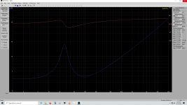
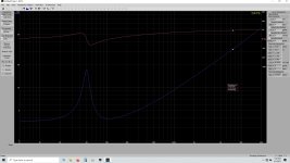
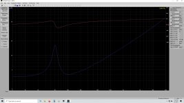
I tried Dayton's DATS measurement device to measure these, with questionable results (carefully following instructions for added mass).
attached are screen shots, showing free air measurements for one driver, and then measured both units ("a" & "b") w/ added mass.
I became disappointed with the DATS, and returned it to the seller.
Do any of the data look useful for figuring out this project?
-C
p.s. I am stuffing these enclosures with 1lb each of AcoustiStuff per manufacturer's recommendations.
Attachments
Well i've tried to simulate Nht 1259 on an online sim ( petoindominique.fr) and it seems to match more or less number you gave for box volume ( circa 40 liter).
It says with an Linkwitz Transform of Qtc 0.707 and FC 33hz, you'll loose something like 6db of max SPL ( half an octave extension as said earlier) and max output circa 99dbspl/1m with 150/160watts.
You'll need something like a notch eq with Q around 1,150 at 44,5hz and a +6db low shelf around 50hz. Should be in the ballpark.
Blue is driver in box, orange eq profile to reach green trace ( 0.707qtc at 33hz fc).
Attachments
Last edited:
Kriviun wrote: "It says with an Linkwitz Transform of Qtc 0.707 and FC 33hz, you'll loose something like 6db of max SPL ( half an octave extension as said earlier) and max output circa 99dbspl/1m with 150/160watts."
My Dayton SPA250DSP amps are spec'd at 250W/4ohms, fwiw.
Looks like I may need to Google & read up on "Linkwitz Transforms" and "Q's of >1,000" to understand the above. We never stop learning, do we?
My Dayton SPA250DSP amps are spec'd at 250W/4ohms, fwiw.
Looks like I may need to Google & read up on "Linkwitz Transforms" and "Q's of >1,000" to understand the above. We never stop learning, do we?
or just read through the links i posted above!like I may need to Google
Yes STV already done the hardwork!
And yes we keep on learning everyday!
@Chasmo57, do you own a measurement mic? If yes then it's a mater of tweaking eq until it match the green curve on the previous linked graphic.
Given the involved freq range close micing ( aka 'nearfield technique') will be ok:
http://www.mh-audio.nl/Measurement.html
http://www.mh-audio.nl/Acoustics/Nearfield.html
"Yes STV already done the hardwork!"
Great-So now comes the easy!
(Sorry, I overreacted to the posts)
So can you help me understand how to use the 5 pole PEQ on the Dayton 250dsp subwoofer amp to accomplish this goal?
(Pretty please).
Measurement device is Dayton imm6 w/ audio tool on iPhone 5s
Great-So now comes the easy!
(Sorry, I overreacted to the posts)
So can you help me understand how to use the 5 pole PEQ on the Dayton 250dsp subwoofer amp to accomplish this goal?
(Pretty please).
Measurement device is Dayton imm6 w/ audio tool on iPhone 5s
Attachments
Your Dayton SPA250DSP has filters with "Q"s ranging from .4 (about 3 octaves wide) to 16 (about 1/10th octave wide).

http://www.sengpielaudio.com/calculator-bandwidth.htm
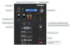
You can see the graphical result of applying 5 different filters of various "Q" in the screenshot from the SPA250DSP manual in post #7, each filter results in shape transformation (amplitude vs frequency) of the signal.
A very wide filter (.4) with frequency set low can be used to emulate a "shelf" filter as used in the Linkwitz Transform orange trace in post #11.
Basically, you apply the inverse of the measured response shape to achieve the desired system "Q".
Apply the -24dB/octave ("subsonic") filter at 25Hz to reduce excursion and maximize the use of your amp power below the point where the filter boosts provide little audible result.
Attachments
Wow.
You gents have helped me truly.

Now to print all this out and don my reading glasses, while sipping a brain supplements smoothie 👴
-C
p.s.Sorry i forgot- did we ever determine if this DSP will allow me to satisfactorily use my 1259's in the 1.42ft3 +stuffed boxes(Qtc~1.2) or must I (with great difficulty) build bigger boxes? Old age
You gents have helped me truly.

Now to print all this out and don my reading glasses, while sipping a brain supplements smoothie 👴
-C
p.s.Sorry i forgot- did we ever determine if this DSP will allow me to satisfactorily use my 1259's in the 1.42ft3 +stuffed boxes(Qtc~1.2) or must I (with great difficulty) build bigger boxes? Old age

Last edited:
Simple approach to set the DSP settings on that amp:
1. Export the predicted (or preferably, measured) FR of the subwoofer as an FRD file
2. Import the FRD file into Room EQ Wizard (REW)
3. Use REW's "EQ" feature to generate the DSP settings required to obtain the subwoofer response curve you want.
4. Configure the DSP with the settings from step (3)
1. Export the predicted (or preferably, measured) FR of the subwoofer as an FRD file
2. Import the FRD file into Room EQ Wizard (REW)
3. Use REW's "EQ" feature to generate the DSP settings required to obtain the subwoofer response curve you want.
4. Configure the DSP with the settings from step (3)
"We" (me) thinks the DSP will allow you to satisfactorily use your 1259's in the 1.42ft3 +stuffed boxes, though I doubt the amp will be able to push them to Xmax (13mm, 26mm peak to peak) in such a small box, which is why I recommended using the DSP's dual-band imiter and a 25Hz 24dB/octave HP filter so you can keep the amp from clipping with the eq required to flatten the response.p.s.Sorry i forgot- did we ever determine if this DSP will allow me to satisfactorily use my 1259's in the 1.42ft3 +stuffed boxes(Qtc~1.2) or must I (with great difficulty) build bigger boxes? Old age
At 30Hz, you could get about 110dB at 1meter from the pair if you had the power.
You may get lucky with room placement and gain and not come close to running out of headroom at the levels you are used to- give it a go.
You can always build bigger boxes/add power if you want more low end.
- Home
- Loudspeakers
- Subwoofers
- How do we use DSP to compensate for higher than optimum Qtc in subwoofers?


