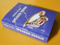
Speaker Repair book

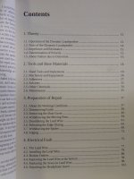
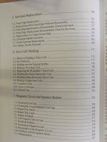
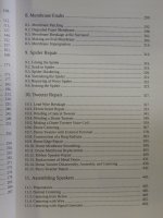
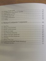
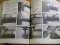
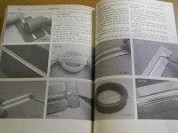
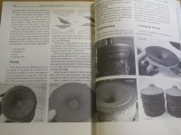
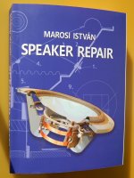
Hello everyone. I repaired loudspeakers in Budapest for 25 years, but towards the end they brought work from neighboring countries as well. I stopped repairing, and there were several reasons for this. There was no room for improvement and creation is closer to me, so I started making speakers. In addition, I would like to move to a farm where production is more feasible, but repair is less. But so that the collected knowledge would not be lost, I wrote down everything I could in a 516-page book. It contains all the information necessary for a beginner with basic technical knowledge to repair any speaker. I described in detail what tools, chemicals, solvents, adhesives and how we used them for the work. In the first 9 chapters, I show you how to make different voice coils, change surrounds, repair diaphragms or spiders. Chapter 10 is all about repairing tweeters. Few people undertake these, so I deal with the topic in more detail. You can find out how to e.g. to wind a dome coil, to make a ring membrane, or to correct their errors. Since there are even fewer people who repair ribbon tweeters, I will show you how to repair five different ribbon tweeters... or make diaphragms. Chapter 11 is about professional speaker assembly, and the last chapter is about making speaker components. I present how, from what, and with what tools paper membranes are made... and I even describe the recipe for my own membranes. In addition, I show how I make plastic and metal membranes, spiders, surrounds, dust covers, tweeter membranes, or flat wire. I think this book fills a gap in this profession, but judging this is not my task. The book can be found on ebay, but you can also order it from me via Paypal. The price is $75 + shipping. I am happy to answer any questions.

Attachments

  • cont 1.JPG
    cont 1.JPG
    447.1 KB · Views: 131
  • cont.2.JPG
    cont.2.JPG
    433.1 KB · Views: 123
  • cont.3.JPG
    cont.3.JPG
    462.1 KB · Views: 123
  • cont.4.JPG
    cont.4.JPG
    398.5 KB · Views: 138
  • inside.1.JPG
    inside.1.JPG
    431.9 KB · Views: 132
  • inside.2.JPG
    inside.2.JPG
    403.2 KB · Views: 122
  • inside.3.JPG
    inside.3.JPG
    423.3 KB · Views: 112
  • inside.4.JPG
    inside.4.JPG
    392.4 KB · Views: 122
  • inside.5.JPG
    inside.5.JPG
    456.6 KB · Views: 118
  • repair.1.JPG
    repair.1.JPG
    381.1 KB · Views: 123
  • repair.2.JPG
    repair.2.JPG
    330.6 KB · Views: 134
  • Like
Reactions: adason

3FE25 or 10F/8414G10 for WAF (yet another how to spend my $ thread) SORRY

I'm planning on a next, hopefully more definitive, project, since someone can get me drivers otherwise unobtainable or really more expensive here.

I like my actual WAF with 6.5 selaed speakers, so i thought i could point my setup in the right direction getting a better High end.

From my research (mostly here) i think 3fe25 is pretty much as good as it gets on a budget, considered CHN-50 but i would rather go with an 8 ohm driver. (TG9 would be interesting but couldn't source them).

Then i sort of liked the 10F/8424G00 because it seemed less inclined towards highs and beamed more harmoniously. But it's over my budget. (They are selling them quite cheap at speakerland if shop is reliable and someone is interested but they don't send to Spain). Then i found the 10F/8414G10 which seems pretty like the former yet at the same time, pretty much the same as 3fe25. I compared this two links:

https://www.dibirama.altervista.org...f-4424g00-extended-range-4-4-ohm-30-wmax.html

http://www.dibirama.altervista.org/...tal-3fe22-extended-range-3-8-ohm-40-wmax.html

And yes, the SSpeak has a little less distortion, a hair more of bass, and seems a little more consistent in the high-end. But apart from that, the other is more efficient and has like doubled Qms.

I don't want to start hoarding FR speakers so ideally this will be the last for some time (forever tweakable tho), and as close to a studio monitor a WAF can get.

Its that situation were u see that first brand pretty thing thru the window and you loose a little perspective. But from a rational point of view, i seriously doubt i could differentiate those two speakers and one cost 3.5 times the other, specially if i get to tweak them a little.

If u heard both of them, and specially, if you played with both of them, given my situation, what would you do?

Of course i accept new drivers recommendations but i rather just decide on something.

Thanks for getting this far 😉

Braun L470 speakers modification

Hello,
Please feel free to express your opinions and advice here.
My audio system is mostly intended for monitoring soundtrack production for self-made films at home. I'm aware that active monitors are the best quick solution. I had before some Adam A3X monitors + subwoofer and they were fantastic. But then I sold them and built my own class-A (JLH 4ohm) amplifier, to learn and start from scratch. The amp is great and loud enough for monitoring, but I haven't found a good set of passive monitor speakers for it.
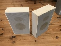
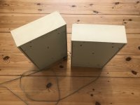
Currently I'm using a pair of second hand Braun L470 boxes that I really like for their flat form factor, since my studio room is small. Combined with an active subwoofer they do well, charm and soft, but I miss the sharp responsiveness and detail of my old Adams. Sweep tests show that these boxes are not very responsive over 10kHz, so I think changing the tweeters could a be solution. I never built speakers, I've only read about it, but I can imagine also that after 30 years the drivers have lost tightness and their soft signature is basically HD. I haven't opened the boxes yet, but I'm considering to change both tweeter and woofer for some modern ones, striving for a flat frequency response between ~80-15kHz (a subwoofer stands below).
I don't know if, since the boxes form factor, damping materials, protective net and construction in general, are exclusively designed for the original drivers, any change of drivers will end up in a complete mess, unless accurate measures and further modifications are made.

Also, if this project of modifying the Braun boxes makes sense at all, I'm also doubting about the type of tweeters to use in exchange, Dome or AMT. I loved the detail and HFR of my old AMT Adams, they really replaced my headphones for fine mixing. But I didn't like the limited vertical dispersion and never really tried good quality dome tweeters to compare with, some SB Acoustics domes that seem popular now.

Any words on this will be highly considered! Since I feel my inexperience on this.
Regards,
Domingo

Attachments

  • IMG_4571.resized.jpg
    IMG_4571.resized.jpg
    782.1 KB · Views: 212
  • IMG_4572.resized.jpg
    IMG_4572.resized.jpg
    418.9 KB · Views: 128

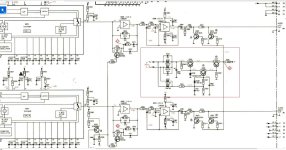
Please help me understand the differences between two similar circuits.

Attached are schematics from the Audio Research LS7 and LS22. I'm trying to determine to what extent the LS22 is simply a balanced version of the LS7. The circuit looks similar to me, but I don't understand it well enough to grok the implications of the changed values/sections.

Attachments

Nelson Pass' Slot Loaded Open Baffle (SLOB) speakers

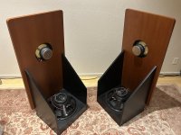
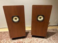
I am selling my SLOBS for $500. I built them at Speaker Camp 2023:

https://www.diyaudio.com/community/...ly-2023-pass-slob-northern-california.399813/

They are as new, though they have a few tiny marks from transport. The speakers must be picked up in near Berkley.

Please let me know if you have any questions.

Attachments

  • IMG_5316.jpeg
    IMG_5316.jpeg
    679.5 KB · Views: 591
  • IMG_5315.jpeg
    IMG_5315.jpeg
    481.3 KB · Views: 796
  • IMG_5314.jpeg
    IMG_5314.jpeg
    424.8 KB · Views: 618
  • Like
Reactions: mordikai

Converting cassette tapes to a digital audio format

Hey guys,

I'm interested in converting some cassette tapes to a digital audio format. I have a Technics Stereo Double Cassette deck and a ATI TV Wonder card which has RCA audio inputs, from which I'd connect the tape deck. I wanted to know if, given this setup, anyone knows if I would be able to convert these tapes and what kind of software I might need (and hopefully might be able to get for free). Thanks in advance.

Eric

Convert F2J to ZenJ?

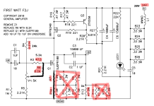
I no longer need a current source amp so thought I would alter my diy F2J to get some damping factor, make it a sort of ZenJ. I don't want a lot of hacks, just short cuts not track cuts. The attached altered circuit diagram shows what I am intending. The revised input resistor values should get me into the ballpark of symmetrical clipping, and I am OK with the resultant gain and input impedance. Should I do anything else?
F2J.png
Many thanks in advance.

Attachments

  • IMG20200423120537362.jpg
    IMG20200423120537362.jpg
    445.7 KB · Views: 159
  • IMG20200423120621251.jpg
    IMG20200423120621251.jpg
    396.6 KB · Views: 159
  • Like
Reactions: Samuel Jayaraj

For Sale Brand New Honey Badger PCB (v2.3) and Parts for Sale

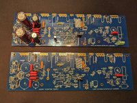
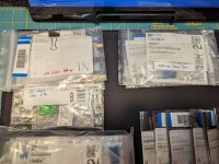
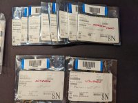
For sale are 2 Honey Badger amp boards and all parts except where noted. The 2 PCB are in very earlier stages of build and are version 2.3. The latest ver is 2.4. As can be seen in the photos, I'm including all the parts I originally purchased from Mouser, and I'm reasonably confident most of the parts (99%) are there. The only part I am aware that is not included are the 2 coils. The 12 output devices are included as well. The parts have been organized by type in individual plastic bags. In addition, generally when I order parts (especially the passive and other small items), I buy more than is needed for the project. However, I did not go back and open every bag and count the parts. There may be a part or 2 missing, so please don't hold that a against me. 🙂

This sale is for the amp PCB and parts only. It does not include power supply PCBs, or parts.

For pricing reference this is what I paid new for these 2 parts below.

2 x HB PCB, $80.00
12 x Output Transistors, ~$36

I'm asking for $210.00 for everything as shown in the photos. Free Priority Mail shipping in the US only.

Please PM me if you're interested and want more detail. Paypal only.

Rick

Attachments

  • PXL_20230618_100256196.jpg
    PXL_20230618_100256196.jpg
    595.1 KB · Views: 258
  • PXL_20230618_100411581.jpg
    PXL_20230618_100411581.jpg
    416.3 KB · Views: 234
  • PXL_20230618_100421839.jpg
    PXL_20230618_100421839.jpg
    438.4 KB · Views: 181
  • PXL_20230618_100430647.jpg
    PXL_20230618_100430647.jpg
    416.6 KB · Views: 183
  • PXL_20230618_100435073.jpg
    PXL_20230618_100435073.jpg
    454.3 KB · Views: 232

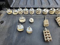
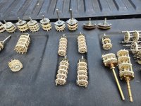
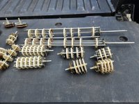
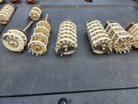
Rotary Switches Galore

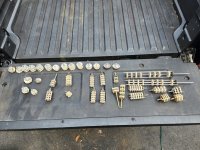
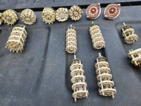
Not really building anymore, and the years of building seemed to create a Tetris-like cache of stuff that I keep stumbling upon. Years of visiting surplus stores WHEN there were surplus stores.

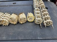
I found a pile of rotary switches. All are US Made and all but 2 are ceramic deck. Some say OAK and some do not have a brand.

I took a bunch of pics. Not sure if anyone is interested in some or all. Please let me know either PM or my handle here 'mpxxxxxx@gmail.com' .

Not looking to get rich here 🙂

Attachments

  • 20231015_130432.jpg
    20231015_130432.jpg
    851.2 KB · Views: 142
  • 20231015_130438.jpg
    20231015_130438.jpg
    904.9 KB · Views: 134
  • 20231015_130442.jpg
    20231015_130442.jpg
    875 KB · Views: 129
  • 20231015_130445.jpg
    20231015_130445.jpg
    839.6 KB · Views: 134
  • 20231015_130546.jpg
    20231015_130546.jpg
    752.2 KB · Views: 118
  • 20231015_130552.jpg
    20231015_130552.jpg
    897.9 KB · Views: 123
  • 20231015_130622.jpg
    20231015_130622.jpg
    793.7 KB · Views: 130
  • 20231015_130625.jpg
    20231015_130625.jpg
    824.4 KB · Views: 134
  • Like
Reactions: Ixnay

Speaking of transformers: instrument amplifier output transformers

So I’m considering building a clone of an old fender guitar amplifier which has me visiting other forums. I’m noticing this peculiar habit people who work on/collect guitar amplifiers have of characterizing an output transformer by its secondary winding alone. In other words, they will speak of it as having an “8-ohm output” or 4 or 16, whatever is the case. Now, my more technical understanding is that transformers are characterized by their impedances which are determined by their turns/winding ratios; ie a 4000 ohm to 8 ohm output transformer has a winding ratio of roughly 22.4:1.

Anyhow, this got me thinking: are there instances where a 4000 ohm to 8 ohm is not also a 8000 ohm to 16 ohm transformer? I mean, I understand other requirements such as bandwidth and power handling are going to dictate core size and winding technique. What I’m asking is is there any such thing as a “16 ohm output”?

Pop sound switching when sources, mute and turn off android head unit

Hello dears,

I have an Android head unit with the following setup:


  • Speaker output socket: for the door speakers
  • 1 RCA output socket: connected to the amp using a splitter
  • Remote power wire
  • Kenwood amp
  • JBL subwoofer

The problem is when I’m switching between radio/Bluetooth or any other source like launching the car link or putting the device on mute I hear a strong pop sound from the subwoofer

Also, when I tried another head unit (the original head unit) the problem disappeared

I tried to measure the output wires and the RCA output using a multimeter in DC mode and I noticed that the reading changed when switching the source

Here are two videos for the measurement process
Speaker wires measure: Login to view embedded media RCA measure: Login to view embedded media

Any recommendations to solve it

Understanding / reverse engineering DSL SM100B

1698866559267.png

While surifing the Danley Sound Labs website for inspiration, I have found the SM100B. It is an 8" coaxial woofer combined with 4 x 8" tapped horn(s) in one box of 52 x 85 x 48 cm, 50 Hz low end cut off (-3 dB, 30 Hz -10 dB) and 124 dB continuous output, 800 W continuos load capacity. Weight is 62 kg. I would like to hear one in person, but it seems like an engineering masterpiece to me. Especially the tapped horn part. I wonder how it is folded inside - I would guess the two tapped horns are each folded slightly differently to use the volume fully. Except for the weight, it looks like a perfect full range box to me.

I also wonder which long throw 8" woofers could be used...it would be a great challenge trying to build one. To model a single TH with 50 Hz cutoff capable of 118 dB continuous output (4 should be then 124 dB if I am correct) would be a good start. Any recommendation for a suitable 8" and/or existing TH design for a single 8"? And if used for the TH part only, would it not be more reasonable to use a 2x15" bass reflex in the same volume (with less efficiency I suppose)?

Big, strange WAW project

Hi diyers,

Having just completed my first fullrange design (pensils with Markaudio Pluvia 7.2HD), I'm planning a woofer assisted wideband (WAW) in order to maximise output and get deep, tight bass. It's following a specific visual design (courtesy of a furniture designer who is in on the project) – see next post. A benefit of the design is that it lends itself to time aligned drivers. I'm not trying to achieve audiophile grade sound, and I don't want to break the bank, but I'd like to produce speakers worth the build/money (and then some?).

In the large cabinet, the Peerless SLS-P830669 seems like a good option. I'm planning to build the cabinet out of 25mm baltic birch ply. Once bracing, port, and driver are accounted for, I'm estimating a net internal volume of 74.5L. I have modelled this with a tuning of 30hz to give an F3 of about 38hz (simulation chart in next post). Up in the sealed 'periscope' part of the speaker, I would ideally use the familiar Pluvia 7.2HD driver. However, I'm keeping in mind that I may need a larger driver to work well with the 12" woofer, so I am also considering the Pluvia 11 (or Alpair 10.3?).

I understand that WAWs are suited to simple crossovers, and I can't access any crossover modelling software because I don't have a PC! (Wine isn't working for me...) So I'm considering using a 66.31uF capacitor for the high pass and a 3.18mH inductor for the lowpass, as suggested by a rudimentary online calculator for a 1st order crossover at 400hz (diagram in next post). However, I'm reluctant to do this build without properly simulating the crossover!

I would love to get feedback/thoughts from the diyaudio community, if anyone cares to jump in. Is this speaker worth building? I have a few specific concerns and questions:
  1. Fullrange power handling/output. I'd like these speakers to run loud. I understand the high pass on the FR driver should allow it to go a lot louder than if it were tackling lower frequencies too, but would the Pluvia 7.2 be outmuscled by the Peerless 12"? Would the speaker produce a slightly feeble output for something of its size as a result? Should I therefore use the larger Pluvia 11 driver?
  2. Is 400hz the right crossover frequency here? I'm trying to protect the critical frequencies above 400hz, but also wanting to squeeze as much output as possible from the fullrange, so not wanting to go too low. There's a bit of a dip in the Pluvia's frequency response at 400hz, but this seems to be compensated in my baffle step simulation (a 2db peak at the same frequency).
  3. Would anyone be up for doing a quick simulation of my suggested crossover network?! I might be able trace the frequency responses if that would make life easier.
  4. Bracing – how elaborate do I need to go? I had planned to go with something fairly basic, like two shelf style braces with four cutouts.
  5. Do I need to worry about minimum phase or polar response? I don't really know what these terms mean.
  6. Finally, I have two options for the port. (1) A cylindrical/round port, 100mm diameter, 268mm long, with a bend in order to fit. (2) A slot port, 422mm wide, 25mm high, and 387mm long. Any preference? The slot seems easier.
I'm incredibly grateful for any advice you might be able to give.

Lewis

Crossover or digital filtering + class D?

Hi all
Im currently building my full range speaker for my home theater
I do have a onkyo tx-nr585
At the moment I have the first version of the front one (planning on having 2 front, 2 back)
they run in bi-amp mode so the woofer is drived seperatly.
im using crossover component (inductor, capacitor and lpad) lend by a friend

So my question is this: would it worth it having a setup of digital filtering and small class d mono amp (like L15DSMD) for each speaker instead of more normal crossover?

the cost of inductor is high so im not sure if it would be almost equivalent. Im not an audiophile and will be very happy with decent audio quality.
would it work with my home theater amp? its not a preamp im not sure im allowed to drive amp with an amp :S

Thanks guys

LXmini Clone

As proof of the concept, I decided to make a clone of the LXmini speaker.
The results are excellent both audible and measurable.
The drivers I used are Mivoc swm 68 and TC9FD18-08 which in my opinion is a far better driver than Seas FU10RB (H1600-04).
I ordered the Seas L16RN-SL (H1480) waiting to arrive to make the final version.
If someone is an expert in designing parts for a 3D printer, they might be able to contribute to the design by designing the upper part that comes on the tube.
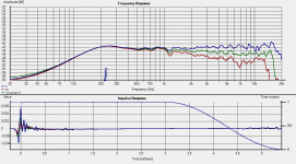
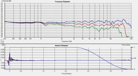
Off axis measurements are 0-22-45.
The microphone I use is Umik-1. It has a horrible feature to bring down the response over 18khz so I don't know the real situation above.
Crossover is terrible minidsp 2x4.
0-22-45.png
a.png
Untitled.png
Untitled1.png
00000IMG_00000_BURST20200601140019790_COVER.jpg
00000IMG_00000_BURST20200601140134066_COVER.jpg
IMG_20200601_135200.jpg
IMG_20200601_135229.jpg
IMG_20200601_135122.jpg

Improving 4558 sound?

What if any practices are done to make the 4558 perform better?
Using it in inverting mode would be obvious, but what other things are there to do? is bootstrapping it worth the trouble?

I admit I haven't thought of them sounding "bad", but I hadn't thought of 2$ headphones sounding bad either until I got better ones. So I'd be more than interested in hearing what there is to say about improving the 4558.

I noticed the other day that the Revox B77 uses a 4558 in non-inverting mode in the playback amp. Maybe that's what people refer to as the "revox sound?" ;D

Selecting optimum frequencies for tone-testing

I’m bi-amping my speakers—Braun LS200. Each individual speaker has a bi-amp switch that will bypass woofers’ passive crossover. So, the active crossover for woofer-to-midrange is required.

To date, I’ve finished establishing the system. Next part is to perform the level matching between woofer’s amplifier and mid & high amplifier. I set the crossover point at 450Hz.

I know the process of level matching should be done by frequency sweep. However, as my amplifiers have been equipped VU meters. I’m thinking to use them instead of using the traditional frequency sweep method. And I’ve already done it. I randomly picked two test tones/ frequencies locating below and above 450Hz. Then, fed them to the amplifiers and adjusted level on each amplifier. After that playing musics to check for tonal balance. Repeat the process until achieve sweet spot. Finally, I ended up with 100Hz and 2kHz combination.

Although I’ve successfully obtained satisfying result. I still have a question. If I won’t use random frequency selection, what is the true method for selecting the optimum test tones/ frequencies?

Let's over-engineer an amplifier!

Objective
1. Must look cool.
2. Must sound great!
3. No smoke.

Build Details

Power amplifier: Volksamp Pass Aleph 30
Pre-amplifier: Conrad Johnson PV-12 clone (from a kit)
Inputs: Unbalanced auxiliary and phono
Outputs: 2 Balanced channels, selectable stereo & mono and line stage outputs for a powered subwoofer.

Let the build begin!
We'll start with the chassis, it will begin Its life as a rack-mount adapter for a Tektronix Oscilloscope.

Image from iOS (2).jpg

Image from iOS (3).jpg


...And enter the apollo 13 replica switch covers...
Image from iOS (4).jpg

And some cheap SPST switches to mockup the panel. I can't find good Apollo 13-ish knobs so they may be 3d printed.

Image from iOS (5).jpg


Aleph 30 kit. Plenty of room in the chassis.
*note: I don't know why the seller packed the contents in a standard bag, seems odd.
Image from iOS (6).jpg


Image from iOS (7).jpg

Ferrofluid type / clarification

Just a quick note on the topic of Ferrofluids. There appears to be quite a bit of discussion over the years on what type of Ferrofluid should be used in what type of driver. With literally thousands of audio drivers being released into the market since Ferrofluid was first introduced as a feature of loudspeakers in 1973 (!) there is no overarching guideline that covers every manufacturer / driver.

There is however, one source of information that provides a basic summary of why type of Ferrofluid / in what kind of driver. It mostly breaks down to density of the suspended fero' particles and viscosity of the liquid substrate which holds said particles suspended, with a dash of importance put upon the ester which coats the metallic particles, keeping them from clumping together.

Here is the chart:

https://ferrofluid.ferrotec.com/products/ferrofluid-audio

Right from the proverbial horse's mouth, so to speak: one of the world's largest manufacturers of Ferrofluid, in operation since the early 1970's. If these folks don't know what they are talking about, I don't know who would...

Also, if you want to get ((really)) geeky in the subject of Ferrofluids, you can't go wrong by spending some time with this document:

https://pubs.acs.org/doi/10.1021/acsomega.1c05631#

Andrew Drouin
www.SpeakerFerrofluids.com
  • Like
Reactions: Marveloudio

Tweaking the FE206eS-R

Please receive my greetings from Paris, France and my best wishes for the new decade.

I currently use Fostex FE206ES-R in nagaoka style of enclosures (fostex recommended enclosures). Very happy with them although it took me a while before I could get the proper damping, filtering, placement of the T90 tweeter, attenatuor…

I have left this pair untouched (no phase plug) except covering the rear magnet with a “felt sock” that can be removed if need be and treating the frame members with felt as well. I did not try to apply some marine latex sealant or duct seal putty between the (motor) magnet and the (chassis) frame as the thing looked very sturdy and did not seem to need something to reduce vibration of the speaker chassis : Modifications and Tweaks - Fostex FE206E and FE206En Fullrange Driver

I have come across a paid of FE206ES-R which have been sitting unused for 10+ years in someone’s inventory. They are brand new but they have suffered from being stored in their shipping boxes, in a environment without heating and probably some dampness.

Everything looks OK, especially the diaphragm and the surround. No tear or deformation / warp of the diaphragm. I have left them “drying out” in my office for a couple of weeks and they look fine. They sound OK as well since I have tested them, although they are just being broken in.

Only the diaphragm is dirty from storage and the whizzer cone edges look a tiny bit “uncrisp” and since I want to build a second paid of FR speakers for my son and may be try out the sachiko build, this is the occasion to get some advice and feedback from the forum and may be tweak this pair of speakers a little more than my original pair.


1) I am thinking to give the diaphragm and the whizzer cone a crispier look and apply a new colour like what Dave from Planet10 has done on numerous speakers. This would remove the grayness of the diaphragm and whizzer and protect them for the future.

I have read many posts and there seem to be some consensus on puzzlecoat (modpodge) or thinned PVA glue to the consistency of a milky solution all mixed with some water based ink we find in Art store. Can’t find the puzzlecoat in Europe so something else needs to be done, liike diluted PVA.

2) I have read that you apply two coats on both the fronts of the diaphragm and the whizzer. The edge of the whizzer at the back should also receive some treatment but not the full back of the whizzer.

3) In some other posts : https://www.diyaudio.com/forums/full-range/133645-coating-phase-plugs-fe167.html I read that the back of the diaphragm (BTW, is the diaphragm what you call “cone” in US ?) can be treated as well. Does this apply to the FE206 ?

4) How many coats do you apply of this thinned PVA glue ? Just two or more ? what is the correct dilution if we start with

5) Other finish to apply after the puzzlecoat treatment ? water based acrylic paint, water based varnish ?

6) Other improvements and recipes that could be shared with me ? There are not many tweaked FE206ES-R around I think.

7) I would still do the “felt sock” treatment as it helped me a lot with finding the right amount of damping. Very little was then needed except some felt behind the speaker and some polyfill.

I will leave the phase plug for another post. From what I have read insofar, this is probably what will bring the most noticeable improvement but I am concerned to cut through an expensive and rare speaker which cannot be found anymore…

Cheers,
Sierra

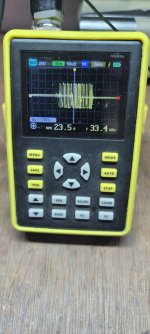
ClassD testing

A quick thought: Do you want to share what kind of testing you do on a new classD design. ( Maybe relevant for all amplifiers, but lets keep to D for now)?

My process is includes something like this (not always in order, - depending on the patience on that particular day)
  1. Have simulations of the different circuit-parts so that you now what to expect when power on.
  2. Power up with slowly rising, current-limited PSU, - watch for stable oscillation
  3. Verify that current-draw is low. sometimes at a Vcc that is lower than design-target.
  4. Verify that gate-waveforms look fine and deadtime is sufficient, - always aim for larger deadtime before everything else is verified.
  5. Check clipping behavior without load and current-limited PSU, - watch for stability with varying degrees of clipping.
  6. Check distortion. Do not optimize anything yet, but verify that its in the right ballpark.
  7. Load with pure resistive 8Ohm and slowly turn up. Verify efficiency and that nothing gets hot.
  8. Load with inductive speaker-load and slowly bring to clipping. Watch for any sign of instability.
  9. Load with capacitor (1uf?) only and verify stability. Check with squarewave-signal and look for overshoot.
  10. If everything above is OK: check with a sineburst signal at max amplitude and maybe lower load-impedance to stress-test.
  11. test with full volume in dummy-load and watch for temperature-rise over time
  12. Check stability with high volume and connecting/disconnecting the load.
Repeat all of the above after every/most design-changes.

Kind regards TroelsM

Edit: spelling

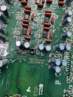
Oppo BDP-105, burned/leaky main caps, damage to the board?

Hi, this is my first post on this forum. I have a Oppo BDP-105 that I bought second hand back in 2016, I left it on pretty much 90% of the time since 2016 ( 7 years ) . I mainly used it as a DAC , I only spun disc once in a while. Recently I started to notice that the front panel display was more faded than usual, also, at times when I play a disc the player freezes. I decided to open it up to inspect and noticed that there were 3 caps that look like they have leaked. Also, there is a brown colour on the board and on some of the soldering. I'm no electronics expert when it comes to these things but I've contacted Oppo and they haven't been able to give me much info other than telling me to send it in. I paid the service fee and will be sending it in this week. Seeing how I am from Canada , it will cost me around $350-$400 canadian dollars after service fee and shipping.

This brings me to my question, is this the kind of repair that Oppo can do? I mean, if the board is damaged, are they able to simply swap the analog board for a new one? Just trying to see if it is even worth for me to send it in given the damage.... What can you guys make of the pictures attached? Thanks!

thumbnail_IMG_6221.jpeg
thumbnail_IMG_6220.jpeg
thumbnail_IMG_6219.jpeg
thumbnail_IMG_6218.jpeg

For Sale Sowter 3603Z 600/600 isolator/Balancing transformer (OCC wire)

SOLD!
Up for sale are used sowter 3603Z 600:600 (input output, balancing) transformers with OCC wire.
I planed to use them for a project but canceled it so I dont have any need for them.

I guess there is no need for a picture, they look very good but if somone wants it no problem!, just ask!

Price only 120 EUR for the pair (2pcs)

Item location EU.

Shipping worldwide.

Site owner contact details for forums.stevehoffman.tv (blocked by Cloudfare)

Apologies if this is not allowed...

I can no longer access forums.stevehoffman.tv due to being blocked by Cloudfare. My current ISP IP address is 105.226.40.249

The only remedy seems to contact the site owner, does anybody around here have an email address for me to use?

What can I do to resolve this?

You can email the site owner to let them know you were blocked. Please include what you were doing when this page came up and the Cloudflare Ray ID found at the bottom of this page.

300B 'Perque' driver

Stumbled on this thing:

http://www.single-ended.com/F5002-300B-Perque-drive.htm

does anyone know anything about it or tried it out? Seems rare. There is another version that uses a mosfet for the pentode grid bias.
Seems like a way to reduce output impedance of the driver stage while keeping cathode bias.
I am trying to understand the circuit and see if there are any advantages vs going to fixed bias.
best

Best way to cover heatsink hole?

I'm sure some of you probably encountered this problem before... How do you cover heatsink holes ?
I got a possible deal on a huge heatsink but it already has holes that won't match my needs (I did check carefully....). Some holes will end up beneath the heat transfer area of the devices I intend to install....
I know different materials will have different expansions with temperature variations so it's probablematic but TBH I don't have experience with this. Is there a tried best method ? I guess another option would be leaving the holes and ignoring them but this will surely affect heat transfer... The question is how much...
Yes, I know an even better option is to pass on the deal, but it's a huge heatsink and a great deal.....

Options for Goldwood GW-212

I don't have access to windows to run any of the modeling software. Is there any option for mac OSX? I kinda hate just asking for people to do designs for me, but don't really have the skills/knowledge/software to do it myself.

I am looking the best options for a high WAF design for the GW-212 because I have a couple of them laying around and my wife wants bass to supplement some DML panels I built for her in her. Hoping for something like 40hz - 200 hz.

PT and OT in close proximity

Hello and thanks for stopping by.

Just curious if mounting grounded metal or mu-metal plates are ever practiced in keeping AC electromagnetic fields from permeating other elements of an amp to minimize unwanted inductance, say, between PT"s and OT's or between power stages and input preamp stages.

Where I understand that proper layout is the best and first line of practical defense for AC induction, is this ever used to successfully address those issues? And are there other issues that can arise from attempting to do this?

Thanks!

Best,
Phil Donovan

Room EQ Wizard Questions (that nobody seems to ever ask OR explain)

I am going through the how-to's now and re-aquanting myself with Room EQ Wizzard - but some questions linger for me:

1) Loopback and Sound Card Calibration

I understand the idea behind soundcard calibration pretty well - but the use of the loopback is a bit fuzzy to me (beyond the calibration). While I DO have a Dayton Omnimic V2 and I DO plan to actually measure room acoustics and loudspeaker response - my imediate use for REW will be measuring active EQ circuits. I fully understand: the sound card L-OUT will go to my active xover circuit and the output [from the xover] will be sent back to the L-IN.

But what about the R-OUT and R-IN? Do I leave these two simply open (not connected)? Or should they be jumped directly (direct loop: L-OUT -> L-IN) for some sort of reference? I think ARTA keeps the "second" channel in full-loop mode for the sake of comparing the input-vs-output of the signal under test. But not too sure about REW.

2) What the hell is "Mic Calibration" for?

Is that not what the factory calibration file (from Dayton) is for? Yes, I have a calibrated SPL meter - and can carry out the calibration. But I am not sure I understand the purpose of this if I already have a calibration file. Does this calibrate some other aspect of the microphone? Will this overwrite the calibration that was provided by my factory calibration file?

3) Have I found a bug with REW?

It seems every time I switch inputs (say, from "Omnimic" to "Sound Card Line In") I notice under the Devices section that - rather than re-use the config for the sound card - it adds a NEW entry. While the ever-growing list of "Input Devices" is only a minor inconvinience, the fact that every time you switch back to an input (and a NEW entry is made), that NEW entry does NOT have the path to the calibration file. Meaning - everytime you switch between inputs - you must manually go into the device config and ensure that the duplicated (new) device entry has the same calibration file specified.

I noticed this SAME thing happens to others on YouTube videos as well and would venture to say it is a bug that likely affects all but has just gone unnoticed?

Every. Single. Time.

This is latest version of REW as of October 28, 2023.

I am sure I will have more questions in the coming days and weeks but wanted to ask these questions since surely someone else has likely noticed or wondered the same but probably been too lazy to ask and wait for an answer.

-Dean

Dim bulb tester, build one in five minute.

Using a Yellow Jacket 2177N 4 outlet power block to make a DBT:
1. Unscrew four screws on both sides of the yellow jacket to remove the metal bottom cover.
2. Unscrew six screws on the inner box (4 on top, 2 on bottom) to expose the wiring.
3. Cut the two wires (see 3rd picture) and connect them together with a wire nut.
4. Assemble everything back together.
5. Plug in the bulbs, Done!
Screenshot 2022-05-31 at 18-44-14 Mail - kuan ng - Outlook.png
Screenshot 2022-05-30 at 15-56-35 Mail - kuan ng - Outlook.png
Screenshot 2022-05-30 at 15-26-54 Mail - kuan ng - Outlook.png

Screenshot 2022-05-30 at 16-26-44 Mail - kuan ng - Outlook.png
Screenshot 2022-05-31 at 10-10-53 Mail - kuan ng - Outlook.png

WTB metal type IV and chrome type II tapes

Hello,

If anyone has an old used metal type IV audio cassette or two, or some chrome type II for a reasonable price, I'd be happy to buy them.
Namely I got nostalgic and bought a Technics 3 head tape deck - one just like I wanted when I was a kid (a long time ago).
I have some Type I tapes and would also like to try better types.
I guess I'm joining the tapehead community.
🙂

Have a nice day!

woofer for closed box: Accuton AS190-9-251??

I am looking for a woofer working in a closed box with a crossover frequency at 200 to 300 Hz. Above will be a bending wave wide range driver and as this has very good transient response and low distortion the woofer should match.
My present loudspeaker uses a version of that bending wave driver and an Accuton S280-6-282 in a vented alignment which was designed to be in a larger room freestanding. As my room is smaller I am trying to design a loudspeaker on the front wall corners (https://www.diyaudio.com/community/threads/on-wall-or-corner-loudspeakers.403432/#post-7458326 ).This would generate a significant room/corner gain and so I am thinking a smaller woofer in a closed box with slower roll off would be more suited. The box volume can be up to 60L but I would prefer a smaller box as this is easier to construct resonance free.
Design wise I like this Accuton cell driver and I see that it has quite low distortion but quite low sensitivity (not a big issue with class-D amps) and has quite a high resonance peak at 2kHz requiring something more than 1st order x-over. Hificompass measured that woofer but had a remark that the loudspeaker (Vimberg) he got it from had terrible bass.

I was also looking at Purifi PTT8.0X04 NABor 08 8inch or PTT10.0X04 NAB (not yet available). These are designed for good midrange performance but I would not use them in that frequency range. I am also not to excited visual design wise.

Noisy preouts on an Arcam AVR350

I've picked up a used Arcam AVR350 to use in a simple 2.1 configuration. I've owned an AVR300 since new so I'm reasonably familiar with the kit.

Excusing the "quality" diagram below... the setup is a pair of speakers powered by the receiver's own FL and FR amplifier channels, and an external power amp connected to the SUB preout on the receiver; driving a passive subwoofer.

Config 2.1.PNG


It was immediately obvious that the subwoofer output is very noisy. A loud buzzing sound at any volume level (except for when the receiver is muted). Sound from the FL and FR speakers is fine (no noticeable hiss unless I turn the receiver volume up to levels that I wouldn't want to use for listening).

Having (unsuccessfully) gone through all the usual checks of grounding issues I reduced the setup to just a single speaker, connected to the FR preout on the receiver, and powered by the same external amp:

Config FR via preout.PNG


That still resulted in a lot of noise (interestingly the FR channel via the receiver's own amp is fine, but noisy via the FR preout).

It could point to the external amp being the problem, so I simplified things even further, and just attached a digital recorder to the FR preout phono/RCA plug. Other than (obviously) power to the receiver there's nothing connected (no speakers, no input sources etc):

Config FR preout phono recording.PNG


As far as I understand (with this receiver), when an analog source is selected you'll always get output to the FL and FL preouts. If the DSP is off (Direct button pressed) then it's a simple pass though, and with the DSP on the input gets processed, then sent to the preouts.

Generating a spectrum plot from the preouts with no input source but the amp volume turned up high shows a spike at 50Hz (UK mains frequency) but then significant spikes every 100Hz. This is present regardless of whether the DSP is on (top) or off (bottom). Understandably there's lower overall noise with the DSP turned off (Direct mode).

FL-and-FR-phono-with-DSP-(top)-and-without-(bottom)-from-preouts.png


I've reproduced the above behaviour on different preout channels (though obviously for a stereo input all other channels are off when the DSP is off, as only FL and FR inputs get passed through in Direct mode).

So; it appears that anything that comes out of the preout phonos is noisy (with or without the DSP enabled), and anything that comes out of the receiver's own amp channels is clean (regardless of whether it's first gone via the DSP or not).

The affected board is the MULTI board (sometimes misspelled MUTI in the service manual). Having pulled the board from the chassis, you can see 4 of the 8 preout phonos (labelled in green). The row of capacitors labelled red are (what I assume to be) part of the line level amplifiers for each preout. On the right (labelled in blue) there's a capacitor (C680) and a black cable going to a ground point near the power supply:

multi-board-labelled.jpg


The schematic for this board shows the 7 speaker preouts + sub preout on the right, and capacitor C680 is at the top of the page below:

MULTI board.PNG


Based on this section of the schematic I'm assuming this area around C680 is providing a ground for this board (the upside down triangle mark). Could it be as simple as a faulty C680 capacitor causing grounding issues and spikes every 100Hz (that only appears to affect the preouts)? I don't have an electronics background so I'm basically at the limit of my knowledge here:

1698415574280.png

Khozmo Display Help

I have a dual Khozmo attenuator set-up and somehow I seem to have "un-synced" the display brightness. The right display is one step brighter than the left and I do not know if there is a way to re-sync them.
It is most apparent at each end of the brightness range. Khozmo has been less than responsive lately at least via e-mail.
Any ideas?
Thanks
Dave

Ewrekaw.jpg


cQPF6fO.jpg

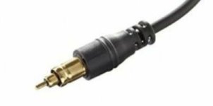
Sony micro plug

Hi all,

Sony back in the 90's was using a so called Micro Plug to connect their earphones to the remote control and then to their walkmans of that era.
The plug is looking like the picture attached.

I have a few Sony walkmans and I need to build an adapter "Sony Micro-plug" to "female 2.5mm regular phono plug".
Does someone know how this type of plug is called so I can look it up in mouser, or digikey?sony micro plug.JPG

For Sale Audio Amateur, audioXpress, etc. back issues

Below is a list of what I have. I've broken them into lots which are reasonable to ship. These are all in very good condition. No writing in them. There is a TINY bit of rust on the staples of some of the Audio Amateur issues, but the paper is fine. Some of the AA's still even have the blow-in cards. Please don't ask me for individual years or issues or to rearrange what is in each box.

Price is $50 per box with FREE shipping included via USPS Priority Mail. (US addresses only).
Single box purchase is fine.

Box #1
======
Audio Amateur
1979 - 4 issues (1, 2, 3, 4)
1980 - 4 issues (1, 2, 3, 4)
1981 - 4 issues (1, 2, 3, 4)
1982 - 5 issues (1, 2, 3, 4, 5)
1983 - 5 issues (1, 2, 3, 4, 5)
1984 - 5 issues (1, 2, 3, 4, 5)
1985 - 4 issues (1, 2, 3, 4)

Box #2
======
Audio Amateur
1986 - 3 issues (1, 3, 4)
1987 - 4 issues (1, 2, 3, 4)
1988 - 4 issues (1, 2, 3, 4)
1989 - 4 issues (1, 2, 3, 4)
1991 - 4 issues (1, 2, 3, 4)
1992 - 3 issues (2, 3, 4)
1993 - 4 issues (1, 2, 3, 4)
1994 - 4 issues (1, 2, 3, 4)

Box #3
======
audioXpress
2001 - 1 issue (November)
2002 - 11 issues (missing October)
2003 - 11 issues (missing August)
2004 - 11 issues (missing June)
2005 - 11 issues (missing June)
Bonus: Glass Audio
1988 - Volume 1, Number 0 (this was an Audio Amateur supplement)
1997 - Volume 9, Number 2
1997 - Volume 9, Number 4

Box #4
======
audioXpress
2006 - 12 issues (includes January through December)
2007 - 11 issues (missing February)
2008 - 8 issues (missing February, July, December)
2009 - 11 issues (missing September)
2010 - 3 issues (includes January, February, March)
Bonus: Audio Electronics
1997 - issue 2
1998 - issues 1, 2, & 4

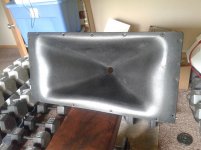
MR94 Mantarays - foam damping?

I found a post by GM - from way back:

Seems reasonable, JBL obviously couldn't build anything that infringed on Altec's patent, but from just looking at the 2360's published data it may be a better sounding horn in a typical HIFI app, though a mouth foam surround smooths the mantaray right out.

And while I have searched high and low - I did not find any details on this approach.

I have to admit that I'm not at all unhappy with how the MR94's perform with 288-8k (metal horns with thick rubber structural damping on the backside)
I of course added some minor notch filters in the DSP. While the top roll-off is not insignificant, it is still manageable.

Would be thankful if anybody could share some details on this or hint me in the right direction.

There is an itch to try out both the 2360's and especially the 5671, which I have heard on one occasion as part of the 5674 system.
Still a bit worried that it might not work given the distance needed for things to come together. 29x29ft room though.

Rotel RSX-972 relay clicking issues

Hello to you all, I've posted the text below as a reply to an old thread but thought might as well start a new one. I have this Rotel RSX-972 amplifier. At first I thought it was completely dead. It did nothing when I pushed the power button. At one moment I left it when still had it powered on, I was doing something else and after about 5 minutes I heard the relay click.. No display or what ever but it kept clicking. Was happy since there was something alive. Opened it up and saw some bad solder joints. resolderded them, still the same. Now pulled the front off and did the same. Turned on and the display turned on and off with the relay click. Been puzzling around and came at the point it stayed on and actually produced sound. So happy again, put it all back together and... nothing. Started to test the different boards by pulling out the inside cables of their sockets and figured out that when I left the cable to the front out, and turned it on it clicked instantly. When I put the cable back in it again took a while and the clicking (front blinking with is as well)interval started to go faster and faster until it reached the point it stays on. So my assumption is something takes too long to get to the minimal amount of current to keep everything on. Any suggestions what this could be? I already changed the capacitors in the power supply but this doesn't work... I am on a dead end now and would be very happy if I get this Rotel working again since it is a very nice piece! Help would be appreciated! Cheers

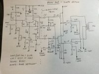
Transistor active low pass filter

Hi Guys,

I have been aske by one of my customers about designing a transistor 12 band graphic eq. My first idea was to use gyrators but the customer stated that he wanted to use active LC filter with discrete transistors. I do not have any experience with that but this is the result that LT Spice is showing. What do you think about that or do you have any experience with that? Thank you very much.

Filter 2.png

Musings on the design of “the big one(s)”

As some of you are aware, I’ve been toying with the idea of building some “stupid power” tube amps for a while. The first tube amp that I didn’t “just throw together, then take apart” happened to be 200 watts and sounds fantastic. Naturally you want to keep going….

Doing it “properly“ by buying $10,000 worth of KT88’s and as much or more on custom iron is completely out of the question. I’ve been collecting TV sweep tubes, and transformer solutions that “should“ work - that is, nothing is run beyond its normal operating range. People (including me) have successfully used power toroids for output transformers. The catch is you’re really limited to 170 volts peak on a 120V winding, and stacking two is as far as you’d dare push it. But Antek makes some that are DESIGNED to put out 1900 volts. THAT got the wheels turning.

Im not planning on re-inventing the wheel in terms of circuit topology. Nothing too fancy, just a Mullard with k-followers directly driving the individual power tubes. This keeps g1 circuit resistance low and allows individual fixed bias. A bias servo will be used to balance individual pairs. This will need to be rung out first, as will overcurrent and excessive g2 voltage shutdown. I know the bias concept works, I’ve used it to balance transistor pairs. I’ll just need to ring out the gain structure and compensation for stability. With actual tubes. I have a batch of 21EX6 earmarked for this development. I figure I’d try to keep it all tube - including little pentodes as current sources for LTPs. If that gives me too much trouble there are always MJE340’s. Like other ‘pro’ amps, the power section would have limited gain, and a front end with 0-20 dB drives it. The whole front end and supervisor would have its own power supply, and the main B+, screen supply, and power tube heaters powered separately with a delayed turn on and shutdown under fault conditions. All this would be common to the various configurations I’ll be looking at over the next ~2-3 years.

Will it ever get built? Who knows. But I have bought the dummy loads for testing and tuning the power supplies, and dug all the transformers out. It always starts there.

Attachments

  • 4B2BE425-8D84-44CE-8638-EA38F55DFA91.jpeg
    4B2BE425-8D84-44CE-8638-EA38F55DFA91.jpeg
    60.1 KB · Views: 173
  • 3B6B1A4A-46FD-4DE5-96E1-D1384EDA990F.jpeg
    3B6B1A4A-46FD-4DE5-96E1-D1384EDA990F.jpeg
    63.1 KB · Views: 179
  • B67C42FF-6232-4F58-A344-CF4C230BD0F1.jpeg
    B67C42FF-6232-4F58-A344-CF4C230BD0F1.jpeg
    75.7 KB · Views: 177

Help JC Power 2500.1

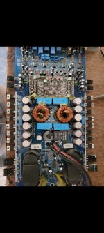
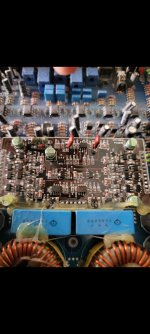
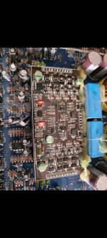
Good afternoon, sorry friends, now I'm looking for help to get this amplifier going, I've already checked the output fets and the driver transistors and they're fine, when I try to turn it on I only see this, I hope I can. help greetings.

Attachments

  • 20230612_170401.jpg
    20230612_170401.jpg
    350.7 KB · Views: 130
  • Screenshot_20230612_175447_Gallery.jpg
    Screenshot_20230612_175447_Gallery.jpg
    275.7 KB · Views: 120
  • Screenshot_20230612_175451_Gallery.jpg
    Screenshot_20230612_175451_Gallery.jpg
    235.3 KB · Views: 120
  • Screenshot_20230612_175454_Gallery.jpg
    Screenshot_20230612_175454_Gallery.jpg
    270.2 KB · Views: 114

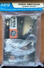
Making a Graymark 509 Safe

Hello,
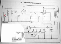
a Couple years ago i picked up this cute little Graymark 509 Amp kit off eBay. I have not had a real use for it but figured it would be a fun project for a snowy day. Well I actually have a use for an upcoming project that i could use this for. BUT i need to make it safe first. this amp does not use a power transformer, but is instead a "Hot chassis" unit connected directly to the AC line. not very safe. Apparently these were part of an electronics course i have read! yikes! So digging around it looks like it can be made safe by using a 1:1 isolation transformer. and I have seen some posts of other amps that use a 50C5, 35W4, 12AV6 combo and it appears they connect the isolation transformer as shown in my badly photoshopped schematic. Is this safe? is this the safest way?

Or should I add a center tapped secondary Isolation transformer and a couple of diodes. connecting the CT to ground and the two dioes before the rectifier tube?


Suggestions on how to make this amp safe. Please and Thank you!


ZC

Attachments

  • 509 Amp Iso.jpg
    509 Amp Iso.jpg
    379.6 KB · Views: 227
  • 1.jpg
    1.jpg
    280.1 KB · Views: 193

Is the Dayton Ultimax 15 the ultimate OB woofer?

https://www.parts-express.com/pedocs/specs/295-514--dayton-audio-um15-22-spec-sheet.pdf

Consider two of these behemoths wired is parallel-series running 400hz on down paired to either a wideband mid tweeter or conventional midwoofer and tweeter…….good lord. QTS and response graph suggests flat OB response below 30hz and clearly those wishing to boost the lower end?…..these drivers can take whatever you throw at em for sure.

Event TR8 XL monitor parts or improvements

Hi guys

As Event Elrctronics (or Rode) is non responsive in 2023.
I have previously posted regarding a fault on one of my TR8XL monitors.
I now can perceive after further deteriation, that a tweeter has fried, producing very high distorted crispy sound.
Any help regarding a replacement part, be it original or alternatives, i would be very grateful. I'm in the UK West Yorkshire, in case any local helpers. If not appreciate any help/advice please, as I am a novice when it comes to electronics.
Thankyou

Linux crossover to FDA amplifiers?

In the past I've used MS Windows-based crossovers working through multi-way DACs to analogue amps. Since then I've moved to Linux, and the PC has become my only source. I also find myself considering class-D amplifiers. Which might logically suggest forgetting about DACs and instead going with FDA Fully Digital Amps. But these are fairly new and Linux sometimes takes a while to natively/widely support new hardware. Also, I'm relatively new to linux, as far as technical expertise goes anyway.

So my question is, how challenging is it to set up a linux-based crossover to multi-way Fully Digital Amps? Can this just work as if the amps are bog-standard/generic USB audio devices, and could something like Camilla-DSP just use these as normal, or is it more complicated to achieve?

Apologies if this is all very obvious, but I'm new to FDA and many of the people using it seem already quite expert.

Thanks,
Kev

6 Pin DIN Input Cable wire ID?

I acquired a vintage Audiomobile system with 3 SA amps8 and a crossover. My car didn't have a radio/receiver, but the system came with 6 pin DIN plugged cable. There are 6 pins, including a center pin.
Can anyone help me identify the wire assignments from the stereo's output?
My plan is to solder RCA cables to a plug to feed the system to test it. Thanks in advance

*SA-1000 (1)
*SA-400 (2)
*CXE-2
  • Like
Reactions: BIGDOGBRODAVE

Measuring capacitance in phono cable

I'd like to measure the capacitance of a cable that is twisted pair with a shield, example: Mogami W2549
Should measure capacitance between the pair of conductors, what about the shield to conductor capacitance?

So here is what I tried. The standard coax type Technics SL1200 phono cable is about 66pF for 47" including RCA connector. I am taking the measurement between two conductors.
But if I try a twisted pair with a shield cable, such as Mogami W2549, I will use the connected shields from BOTH channels (L+R) as the ground wire. The shields will become my ground wire, connected on the pre amp end and also the turntable chassis, just like the regular ground wire gets connected.
How do I measure capacitance now? Do I add the capacitance between "positive" and "neg" conductors and ADD the capacitance between "pos" and the shield and also Neg and the shield?

thanks!
Projects by fanatics, for fanatics
Get answers and advice for everyone wanting to learn the art of audio.
Join the Community
507,700
Members
7,884,948
Messages

Filter

Forum Statistics

Threads
406,069
Messages
7,884,948
Members
507,700
Latest member
Tomasz 026