I'm Chilort

I guess I never posted an intro. Oops. So much for following instructions.

I've been around other forums for close to two decades. I tend to come and go as my interests come and go. I was an electrical engineer in my first career (changed to something else after 4 years in industry watching the leadership in the companies I worked for flail and fail all over the place).

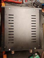
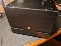
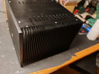
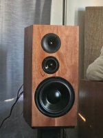
I've done quite a bit of DIY. I've built my own chip amp with my older daughter to see if she has the knack. I've built Econowaves, several lilmike horns subs, flat packs from DIYSG, and (for my first ever speaker build) a pair of desktop speakers from scratch (packed away these days and should probably be burned in a fire).

Looking at another career change after over 20 years in the current one and it'll likely be something in audio. Time will tell.

modeling a loudspeaker using transfer matrices

Hi everyone,

I am trying to make my own simulating tool using GNU Octave and transfer matrices methode. I am encountering difficulties in validating my simple model (infinite baffle) because it does not match hornresp results. i think i am not that far from a correct model but not here yet. as you can see phase and SPL are not the same as hornresp.

below is the code with some comments. Note that i do not think problem come from my radiatoin impedance since i used this function for analytical modeling and results mached hornresp with my analytical model.


Code:
clear all; close all; clc;

[c, rho, P, P_ref, Air_Imp, f, w] = Generals();  % initialise constantes and frequenies
wc = w / c; % wave number

driver = 'RCF_MB15N405.csv'; % Selecting driver
r = 1;          % Distance to from the source
eg = 2.83;      % Input voltage

% Thiele/Small parameters
[Sd, fs, Vas, Qms, Bl, Re, Le, Xmax, Mms, Qts, Qes, Rms, n, dr] = TS_extract(driver, 1);
Cms = Vas / (rho * c^2 * Sd^2)  % Calculating mechanical compliance
Pg=eg*Bl/(Sd*Re);
mas=rho*Sd;
% Radiation impedance uing bessel and struve functions choose
[zar,zmr]=RadImpC(Sd);
% Loop for each frequency
for k = 1:length(w)
    % Transfer matrices for sub domains
    tre(:, :, k) = [1, Re; 0, 1];                           % voice coil resistance
    tle(:, :, k) = [1, 1i*w(k)*Le; 0, 1];                   % Inductance
    tem(:, :, k) = [0, Bl; 1/Bl, 0];                        % gyrator
    tmm(:, :, k) = [1, 1i*w(k)*Mms; 0, 1];                  % Mobil mass
    tcm(:, :, k) = [1, 1/(1i*w(k)*Cms); 0, 1];              % Compliance
    trm(:, :, k) = [1, Rms; 0, 1];                          % mechanic losses

    % Electromechanic chain
    tdr(:, :, k) = tre(:, :, k) * tem(:, :, k) * tmm(:, :, k) * tcm(:, :, k) * trm(:, :, k);

    % Calculating Iin [A] electrical current from the source from electro-mechanic
    % matrix [A,B ; C,D]
    t12 = tdr(1,2,k); % A
    t22 = tdr(2,2,k); % B
    zin = t12 / t22;  % Impedance seen from source
    ein = eg;         % Input voltage
    iin = ein / zin;  % Input current
    In = [ein; iin];

    % Acoustic domain
    tma(:, :, k) = [Sd, 0; 0, 1/Sd];                        % Tranformer
    tza(:, :, k) = [1, zar(k); 0, 1];                       % Radiation Impedance

    % Complete chain from eletrical domain to acoustical domain
    Tt(:, :, k) = tre(:, :, k) * tem(:, :, k) * tmm(:, :, k) * tcm(:, :, k) * trm(:, :, k) * tma(:, :, k) * tza(:, :, k);
    Ttinv = inv(Tt(:, :, k)); % Inverting matrix
    Pu = Ttinv * In;          % Calculating results

    % Pression (pout) et vitesse acoustique (uout)
    pout(k) = Pu(1); % Acoustic pressure at Sd
    uout(k) = Pu(2); % Acoustic volume velocity

end

Pa = pout ./ (4 * pi * r);  % Acoustic pressure at 1 [m] from the Sd
SPL = 20 * log10(abs(Pa)/ 20e-6);  % Decibel SPL
G=1i.*w.*mas.*uout./Pg; % system gain
Phase_deg = unwrap(angle(G)) * 180/pi;  % Phase


[fh,o,ph]=hornrespcsv("ibn4050.csv");
figure(1)
semilogx(f, SPL, 'LineWidth', 1.5, fh,o,'LineWidth',1.5);
xlabel('Frequencies (Hz)');
ylabel('SPL');
title(['SPL response']);
grid on;

figure(2)
semilogx(f, Phase_deg, 'LineWidth', 1.5,fh,ph,'LineWidth', 1.5);
xlabel('Frequencies (Hz)');
ylabel('Phase');
title(['Phase']);
grid on;


Capture d’écran du 2025-04-18 09-21-38.png


Capture d’écran du 2025-04-18 09-22-13.png

Question regarding available options for studio monitor builds

hello everybody and thank you for taking the time to read!

I am on the quest to find some very nice studio monitors to mix on for years to come, all while not breaking the bank and not wanting to pay for things like brand image, warranty, marketing and service.
At the beginning I was on the lookout for used speakers (the likes of Amphion One15 / One18, PSI A17m, etc) as they would probably render me with most bang for buck possible, though now I have come across a few people who have decided to build their own speakers, but I have to say that finding folks who are building studio monitors specifically appears to be quite rare.
I personally am rather proficient when it comes to technology, building (woodworking), soldering, and engineering to some degree, though having looked at all the things that go into a capable and usable speaker design I am not certain building a studio monitor from the ground up that rivals the likes of ATC, PSI and Amphion is something I am capable of doing.
It seems then I will probably not go the traditional, full DIY route as for me the focus is 100% on the final product and not so much the way of getting there.
Sure, it seems interesting and romantic to design, conceptualise and build my own custom speakers, though I would probably spend a lot of money simply on all the testing, measuring and so on and so forth.

A few days ago, I came across the SEAS King RO4Y MkIII speaker kit and it seems to almost fit the bill.
On the surface, it looks like the most bang for buck that it is going to get for my application (a 3k kit that potentially rivals 10k+ speakers?).
I am of course aware that it is not exclusively the price that determines the value of a pair of speakers for ones application (the specifics matter: components, room, usage, etc), so I am unsure wether or not this Seas kit is my only good option and if it is even a smart idea to begin with.
For reference, I am in a rather small room 4mx3m currently, though it is pretty well treated with very dense absorbers and for what its worth I am getting a very good response with my (of course considerably smaller) Adam T5v monitors. Also note that this is not the room I will be staying in as I will most likely move to one that is a little larger in the near future, if that at all adjusts the equation.
If I had unlimited money I would probably buy the ATC SCM25 Pro monitors as I love their sound signature (clear, natural and forward mids with little distortion), but I simply cannot fork over the 7k (used price that is) they cost, so I am essentially looking for a similarly performing speaker that would fit my budget a little better (around 3k).

I would be very thankful for more experienced people to give me some sort of guidance as to what would be best in my current situation and if DIY (or building a kit) is the best option to go with, or if I should simply go out and buy a used pair of Amphions, PSI's, or other higher end speakers that fit my budget.

Sharing projects out of Germany

Hi everyone!

My name is Markus, I am based in Munich, Bavaria.
I have known this forum for quite some time now and have finally decided that I'd like to share some projects on here as well!
Audio electronics has been my gateway into electronics and even led me to switch my major to electrical engineering. I have been designing audio circuits as a hobby for a several years now, time and time again drawing inspiration from some of the amazing projects on here too!
After being passive for so long, it really feels nice to take the step to actively sharing as well. I really look forward to the interactions on here!

Thank you all in advance 🙂

Markus
  • Like
Reactions: Drbulj

Desktop power Amp

I have the project, clear and well defined - for now on paper, but I have all the ingredients or almost, the video card is missing, but it could arrive in the next few days. for now without photos, these are the components:

¹ Soundstream Reference 300 75W*2
² stabilized power supply 14Volt 50amp
³ Big Cap - large stabilizing capacitor and current accumulator

PC
|
Sound Card
|
(this Amp)
|
Passive speaker (LS 3/5a hybrid - finished)


----- software - microphone - - - & more


These will be the amplifying part of the Desktop Audio system.

Best OpAmp for driving 600 ohm load

I'm looking for the most suitable, commonly available op amp for driving a 600 ohm 1:1 ratio output transformer. I prefer to be able to drive it cleanly to +10 dB.

There's obviously the NE5532, but the distortion is too high for my tastes. The 4580 comes to mind, but that one isn't the best in terms of slew rate, despite the low impedance capability.

Any suggestions?

For Sale BC/VISHAY 15000/40VDC

I have approximately 85 of these beauties. Ripple current 7.8A according to Mouser, who also list them at $21 in 300 quantity.

Note they come with stud, so you need a plastic nut to mount them. Or saw off and use a clamp.

Three full boxes of 25, screws and washer included. Rated at 85 degrees.

I’d like to get $10/pcs. Minimum would be like 8 of 10 pcs. Shipping at cost.

R

Attachments

  • IMG_2300.jpeg
    IMG_2300.jpeg
    415.3 KB · Views: 54
  • IMG_2297.jpeg
    IMG_2297.jpeg
    1 MB · Views: 49
  • IMG_2298.jpeg
    IMG_2298.jpeg
    903 KB · Views: 47
  • IMG_2299.jpeg
    IMG_2299.jpeg
    605.5 KB · Views: 41
  • IMG_2296.jpeg
    IMG_2296.jpeg
    532.2 KB · Views: 41
  • IMG_2293.jpeg
    IMG_2293.jpeg
    1 MB · Views: 47

Ground control

I have some ground control problems, but not Space Oddity of David Bowie. That can be a nice song in the background while reading this.

This is not my first amplifier build, so I have some knowledge and have had and solved some ground problems in the past, but this one is killing me.

First picture of amplifier layout:
20250422_174826.jpg


Normally I build dual transformer/dual psu units. This time I decided to reduce cost and used one 600VA toroid. I have tried some different layouts of wiring, but same result.
1. With nothing connected to inputs the amplifier is absolutely silent.
2. With inputs connected together with cable - each to other, the amplifier is absolutelly silent
3. With inputs connected to source there is noise - bzzzzz. Source is Marantz amplifier with preouts - no issues with other amps.
I tried to change grounds from connector to just one point, a screw in the picture on top of capacitors, same problem.
Tried ground lift with greatz, same problem.

The solving of problem was removing the connection from common ground (the green yellow) to the eart point on top near the big resistor, where the chasis is grounded. You can see now the wire on top of the screw of common ground. If I connect this to chasis earthing point there is noise. On other amplifiers, without this wire I had noise, with this one the oposite.

What is the cause of this and can I just leave it like this. The chasis is grounded to the mains jack, but the amplifier 0V -ground is NOT.

Attachments

  • 20250422_174826.jpg
    20250422_174826.jpg
    443.4 KB · Views: 69

QUAD 33/303 reboot

Not much info yet:

0524_munich_quad_05-600.jpg


the new Quad components will be available within six months. The 303 will offer 60Wpc, cost approximately €1500 apiece, and include balanced and single-ended inputs and outputs, a remote control, a phono stage, and the original Quad’s “tilt controls.” The 303 prototype was very heavier than it looked. The classic orange buttons had excellent touch.

dave

Decoy driver fun sub project

The wait for new oscilloscope and procrastination is killig me.

So I got a new idea in the endless chain of very stupid ideas. Making a sleeper subwoofer design, that looks weak, but sounds unexpectedly mighty for the looks.

It should be rather compact looking design or halfway in-built design into the wide "office table leg".

The idea is either a tapped horn looking style, with weak 6"-ish driver magnet exposed for view, or ported design with unimposing frontward facing 6" cone sticking out for view.

The true drivers will be one of the three:
1) Logitech Z-2300 woofer driver (basically respected 8" Tang-Band driver).
2) Mid grade 8" car audio driver with even more oomph (Hadex 338).
3) something new from Soundimports.eu

Where I'm lost is to find best decoy driver (could be a passive radiator too), making it plausible by looks, and making it move when the design is working, either electrically or as a passive radiator, that needs to be managed to not get overwhelmed by the strong driver in the background.

Ideas welcome!

SSR for power amps

Solid State Relay - SSR
I tried to find ready made SSR on web but not mach choice there so I designed my own one.
Here is SSR with quite new MOSFET driver Si8752.
I did two versions with TO220 mosfets and TO247 mosfets.
It includes DC offset detection and turn on delay.
Attached schematic and PCB layouts, if anybody interested to buy the PCB let me know.
Damir

Correct schematic is here: https://www.diyaudio.com/forums/solid-state/355093-ssr-power-amps.html#post6219435

Gerbers here: https://www.diyaudio.com/community/threads/ssr-for-power-amps.355093/page-3#post-7797854

Attachments

  • SSR + DC offset detector with delay.sch.jpg
    SSR + DC offset detector with delay.sch.jpg
    167.8 KB · Views: 1,668
  • SSR + DC offset detector with delay -small-photo.JPG
    SSR + DC offset detector with delay -small-photo.JPG
    808.5 KB · Views: 1,583
  • SSR + DC offset detector with delay -big-photo.JPG
    SSR + DC offset detector with delay -big-photo.JPG
    835.3 KB · Views: 1,519
  • Like
Reactions: nfsgame

For Sale 2x ICEpower 1000A + 2x Power supplies, project

I have for sale an dual mono ICEpower 1000A amplifier that I built few years ago. I used it to drive a pair of subwoofers until one channel went silent. I tested at that time and the second channel power supply died. The other channel works normally. The amplifier modules are genuine. There is enough power in one power supply to feed both channels.
I have taken out a diy controller board for better use, it used to control power button and turning on/off the amp boards, although you don't need it to make it functional. All other parts and modules and wiring is in place, see images. Sorry for bad quality photos, the front plate does not have scratches it is just dust.

It is assembled in a beautiful PASS style smallish enclosure, roughly 10"x10"x10" size.

My asking price for the complete set is 450€ 250€. Can be shipped to almost anywhere. I'm shipping from Finland, Europe.

Attachments

  • IMG_20241124_184019.jpg
    IMG_20241124_184019.jpg
    700.7 KB · Views: 267
  • IMG_20241124_185231.jpg
    IMG_20241124_185231.jpg
    735.8 KB · Views: 268
  • IMG_20241124_183725.jpg
    IMG_20241124_183725.jpg
    348 KB · Views: 213
  • IMG_20241124_183748.jpg
    IMG_20241124_183748.jpg
    349.9 KB · Views: 203
  • IMG_20241124_183734.jpg
    IMG_20241124_183734.jpg
    323.9 KB · Views: 262

Calling all Calgarians - Get-Together 2025

Calling all Calgarians!

It seems we have a bit of a diyAudio continent in Cow Town. Notably, @bxt2008, @leadbelly, @kirks, and likely others. In a recent thread I floated the idea of a get-together over a few pints at some point and there seemed to be some interest.

So how about this: We meet at Two Pillars Brewery (910 Centre ST N) at 8pm on Wednesday January 15, 2025. The idea is just to put a face to the user ID and to chat/BS about all things audio.

Please respond below by January 7 if you plan to make it. If it turns out we'll be more than Two Pillars can accommodate I'll find a larger venue that's reasonably central.

Hope to see you at Two Pillars!

Tom
  • Like
Reactions: Gill.T

How do you personally set mid/tweeter CTC spacing?

Hello. I have read a number of rules of thumb about mid tweeter driver spacing. I'm wondering what the actual process looks like for y'all

Here is how I have opted to do it for the project I'm working on now. I'm mating the Dayton ND25FW tweeter to the Dayton DS90 mid. I looked at manufacturer supplied graphs, and figured anywhere from 3-4KHz would probably work as a good crossover point. I settled on 3700Hz as a starting point. So I used the kimmosto rule which specifies the wavelength of the crossover point * 1.2 should be your CTC spacing. In this case
3700Hz is 3.66".
3.66*1.2= 4.392
So I made the spacing 4.4", and have 3700Hz as my starting point for crossover work.

How do you guys do it? I know some people just put them as close together as possible. I've heard below 1 wavelength CTC as another rule of thumb. I'm assuming some people use sims like akabak. I wonder if anyone makes vertically adjustable baffles and plays with spacing until they find a sweet spot? I'm just interested in the process here among other DIYers.

Attachments

  • 20241007_173506.jpg
    20241007_173506.jpg
    274.6 KB · Views: 38

Iron Pumpkin(s) and other smaller vegetable animals

Well , it started long ago …. when I was really young(st)er, full with naivete and BS , came to pretty novel idea to make xformer loaded tube line stage …
Result of first tests , hardly optimal ( using two halves of 6SN7 in parallel and loaded with ancient xformer from vertical section amplifier of ancient B-W tube TV set) , I was blown with ‘till then unknown dimension of sound – everything was so alive ….
Later I made several iterations of line stage with same approach , being so proud for reinventing boiled water , until I got some xerox copies of Sound Practices , where I found that even in boiled water reinventing I wasn’t first ….. boyz from Italia already made Euridice preamp ; anyway , intermediate iteration was with two halves of 6DJ8 in parallel , latest one being with ubiquitous EC8010 and custom made xformer . That being even published on my old site – WOT preamp and battery charger 😉

Attachments

  • Choky's WOTcirc.gif
    Choky's WOTcirc.gif
    21.9 KB · Views: 5,458

For Sale Passive preamplifier. Relay attenuator.

Selling a preamplifier (passive). Control via encoder or remote control.
Four inputs and one output.
A logarithmic attenuator is used as a volume control.
Attenuation -96 dB, adjustment step 1.5 dB, option on Vishay 1% resistors, FUJITSU relay.
A 32 * 8 LED matrix is used for the display.
After switching off, all pre positions (channel, volume) are remembered.
The amplifier has an absolutely neutral sound.
Display brightness adjustment and the ability to completely turn off.
Remote control included. Price $300 plus shipping.

IMG_3881.JPGIMG_3868.JPGIMG_3851.JPGIMG_3883.JPG
IMG_3847.JPGIMG_3860.JPGIMG_3870.JPGIMG_3873.JPG
  • Like
Reactions: itsikhefez

Volume Control Relay Attenuator passive preamp

A stepwise volume control is implemented with a set of tiny relays and resistors. In a high-end audio system, a noticable sound improvement over potentiomeneters is obtained, also compared to 'audio grade' potentiometers. Its IR remote control provides convenience over solutions with stepped attenuator rotary switches. The sealed relays will maintain contact quality over a practically endless lifetime. The design represents a audio 'preamplifier' of top-class sonic quality, in a compact and affordable implementation.
The design uses high quality Fujitsu FTR-B4CB4.5Z bistable relays, as well as mil-grade audio grade resistors RN55D, RLR07, CMF55 from Vishay-Dale, which have an excellent reputation in the audio field. The circuit is designed for high-quality audio applications.
The input impedance is constant 10K, 22K, 50K, 100K.
The 1.5 dB adjustment step covers a sound attenuation range of 94.7 dB, 63 steps. By eliminating any active electronics, a very clear and open sound is maintained. There are no clicks when adjusting the volume in the speakers. Encoder for control from the panel.
The IR receiver allows remote control. When the power is turned off, the last volume position is remembered.
The circuit operates from a stabilized voltage source of 5 V.

The input impedance is constant 10K, 22K, 50K, 100K.

Payment is possible via Payoneer or to a bank card. It is also possible to buy on Ebay.

Stereo controller kit (2 channels), includes: the controller itself, IR remote control, encoder, indication on two segments with IR receiver


https://www.ebay.com/itm/267166457170
https://sgaudioua.etsy.com/listing/1798144856
https://sgaudioua.etsy.com/listing/1871270901
Stereo controller kit (2 channels), includes: the controller itself, IR remote control, encoder, indication on two segments with IR receiver
Input selector for 4 stereo channels

https://sgaudioua.etsy.com/listing/1825237975

https://www.ebay.com/itm/267166457170

https://www.ebay.com/itm/266863103276
https://www.ebay.com/itm/266932731942
https://www.ebay.com/itm/267151831175

Stereo controller kit XLR (2 channels XLR), includes: the controller itself, IR remote control, encoder, indication on two segments with IR receiver
Input selector for 4 stereo XLR channels

https://www.ebay.com/itm/267197617946
https://sgaudioua.etsy.com/listing/1824028825
https://sgaudioua.etsy.com/listing/1825237975
https://www.ebay.com/itm/266918250389
https://www.ebay.com/itm/266936692441

Stereo controller kit (8 channels), includes: the controller itself, IR remote control, encoder, indication on two segments with IR receiver
https://www.ebay.com/itm/266863035366

Stereo controller kit (6 channels), includes: the controller itself, IR remote control, encoder, indication on two segments with IR receiver


IMG_3748.JPG


IMG_3747.JPGIMG_3746.JPGIMG_3745.JPG

Attachments

  • IMG_3733.JPG
    IMG_3733.JPG
    335.2 KB · Views: 271
  • IMG_3755.JPG
    IMG_3755.JPG
    420.6 KB · Views: 275
  • IMG_3758.JPG
    IMG_3758.JPG
    421.9 KB · Views: 276
  • IMG_3794.JPG
    IMG_3794.JPG
    328.7 KB · Views: 64
  • IMG_3797.JPG
    IMG_3797.JPG
    586.7 KB · Views: 71

Faital HF146 vs HF10AK - Top End Performance

I have been considering both of these drivers for the HF of a music speaker system that will cross likely to a 12 or 15" woofer that is yet to be determined. Obviously there are huge differences in these drivers, but am wondering how much HF I give up by going with a crossover a little lower and using the HF146 vs the HF10AK? Graphs tell me only so much, and wonder what others have experienced or implemented to close the gap - if at all possible!

At present I own the B52 clones of the QSC 1" guide and a pair of 18 Sound XT1464. My system is triamped with a DBX Driverack 260 handling DSP duties.

My intention was to do ULF likely with some 18" JBL 2245's, so I am not sure if there is anything to gain going 1.4/15" vs 1/12". I certainly wouldn't like to sacrifice HF, since LF is less of a priority due to the JBL. Maybe I just answered my own questions, but without asking, I am unsure if anyone has had experience/success comparing these drivers/guides.

Search has shown the XT1464/HF146 combo to be nice, and lots like the HF10AK for how smooth it is... would it mate well with a guide like the QSC everyone likes so much? I'm certainly open to suggestion as well.

Bettering the Jean Hiraga 30W Amp

Hi !

I built the Jean Hiraga 30W Amp, and I absolutely love it's sound. Its my main amp as of now. But the DIY bug continues to prod me to strive for something even better. Hence this question.

in your opinion, which Amplifier, whether Class A/AB/D will you rate as giving a (distinctly audible) better quality sound than the JH? What did you find better. If you have done an A/B comparison that will be great.

Thanks. !!

Does Variovent really extend bass response?

Hi everyone,

I would like to share my thoughts after trying to modify the worst sounding speakers in my modest collection - a beautiful pair of Blaupunkt Lab 208. They look like a million dollars but have problems with HF (very directional), boxy sound even when not hanging on the wall and almost zero bass under 100 Hz. About 5 l netto volume, closed cabinet with two (Audax?) 13 cm woofers and one paper cone tweeter. They even have a proper crossover with two solid air inductors and two bipolar caps.

The first thing to check when addressing the boxy sound was a textile mesh under a wooden grill (a wooden one with several holes about 11 mm diameter and 3 mm depth) strengthen with some transparent paint. This textile dust protection under wooden grill was so glued with some hard chemicals that under magnifying glass only one per 10-20 micro-holes was open. So first I cut out the textile protection from all the wooden holes (baffle) and replaced with an "acoustic transparent" open cell foam.

To my surprise it brought no effect. No impact on overall SPL or SPL in frequency domain graph. Zero. Null. The boxy sound remained, which was even visible on the measurements (REW, UMIK-1) in the form of a 120 Hz peak before very early bass roll-off. The next solution I came up with was to remove one of the woofers to change the system overall Q value to alter bass roll off characteristic. And yes, that brought some improvement (of course I added an L-pad to the tweeter and parallel resistance to the remaining woofer to match, sealed the baffle hole in place of missing woofer) but the boxy character remained. Replaced not-a-good-looking damping material with polyester wool (3M calls it Dacron) - no effect.

After some research to find the remedy for too small cabinet (these boxes are only 10 cm in depth) I found - that was what I had thought - a solution. Variovent. After reading several sentences on the web telling "oh, I just added a variovent to my subwoofer and it improved bass extension very much" I decided to give resistive loading a chance in my Blaupunkt Lab 208 speakers. As engineering of such s port was not very demanding, the Blaupunkts quickly received a stuffed area under the grille in place of a missing woofer.

And now... I am not sure what to tell 😉

After experimenting with different damping materials, port area, port diameter and damping density, there is inly one thing I can tell: resistive loading does not extend bass. It was obvious after first measurement and proved with the following ones. First thing was a drastic early roll-off on the LF side of graph. And the second was a change in a system's resonant frequency which increased so significantly that it made such a speaker system virtually useless.

As I do not have a specialized gear for impedance measurements, I did it the traditional way with a serious resistor and analog multimeter. Started with the whole "variovent" closed, so the closed cabinet. The woofer has Fs of about 45 Hz. In the closed 5 l cabinet with the other sibling woofer it increased to 100 Hz and with missing second woofer to 85 Hz. That was the starting point. And then I uncovered the holes in the wooden front of the baffle where a resistive loading port was located, one by one. The results destroyed my faith in this "variovent" solution.

Two holes of a port open - 120 Hz. 5 holes - 145 Hz. 15 holes - 185 Hz. And then up to about 220 Hz of a system's resonant frequency with a "variovent" port fully open. "Fully" means an open surface calculated with some equation found on the internet. And now the question comes: does resistive loading make any sense? Is it really a solution for too small a cabinet? Because from my point of view it is only usable in a very low tuned system, to make impedance curve less aggressive, but always at the cost of bass extension.

Could anyone please say or prove that I am wrong? 🙂 I am pretty sure I am because there were several constructions with resistive loading, can be found on the vintage market and they had to be working as some of them are classics. If you wish, I can share some photos of the work with the Blaupunkts Lab 208 as they are too pretty to believe they play so bad 🙂 They are very solid and beautifully made as a furniture, but have so many sonic problems it is hard to believe they made success on the market. Comb filtering of the tweeter signal because of a drilled-holes concept of a baffle? Not sure yet, but that could also be the case 🙂

Vario-vent, or not to vario-vent them?

Regards,
Mike

Best 12" woofer for open baffle midbass?

I'm looking to buy 12" woofers for OB midbass and have narrowed down to these:
  • Acoustic Ellegance LO12 - $639 - designed for OB applications
  • Beyma 12BR70 - $155 - used in the Caladans with very good comments
  • SB Audience Bianco 120B150 - $99 - designed for OB applications
Below these midbasses I have sealed subs playing from 70Hz, and above them have an 8" in OB and looking to cross them at 400Hz.

Anybody has experience with two or three of these to compare how they sound/perform?

I also need to decide between having 1 or 2 per side.

Thank you!

Yet another rectifier

Building the power supply for my Wolverine and inspired by the incredible build photos from @stuartmp and @danieljw, I decided to learn KiCad and do my own dual full-wave bridge rectifier pcb. I would have used the one from @prasi, but I wanted to use screw terminals instead of quick-connect tabs. That's the nice thing about doing your own -- you can use whatever hardware you prefer. So for anyone who hasn't taken the plunge, I highly recommend it. It's really pretty easy -- KiCad is amazing -- and quite fun. So thank you to @stuartmp, @danieljw, @prasi, and @xrk971 for the wealth of info you've shared in these forums that inspired me to take that plunge.

Fwiw, here's what I came up with. It's an active rectifier using the LT4320 Ideal Diode Bridge Controller like @prasi's combined with features that I see in the photo of @stuartmp's dual bridge rectifier pcb. So it's kind of a hybrid between the two. The key features are:
  1. Dual active rectifiers using the LT4320
  2. Can use either screw terminals or quick-connect tabs
  3. Supports a ground lift circuit to connect to chassis ground
  4. Supports indicator LEDs onboard, offboard, or both
  5. Supports bleeder resistors
  6. Supports the RZ/CZ components as on @stuartmp's pcb
Confession: I'm not sure what RZ and CZ are for. I included them just because I see them on @stuartmp's pcb. I assume the Z stands for Zobel, so I've been reading about Zobel networks, but I still can't map what I see in the pcb photo to what I've been reading. And that's my ulterior motive for posting this. Maybe someone can answer this question for me.

Attachments

  • FullWaveActivator-Built.jpg
    FullWaveActivator-Built.jpg
    507.2 KB · Views: 185
  • FullWaveActivator-PCBback.jpg
    FullWaveActivator-PCBback.jpg
    436.2 KB · Views: 162
  • FullWaveActivator-PCBfront.jpg
    FullWaveActivator-PCBfront.jpg
    585.5 KB · Views: 161
  • FullWaveActivator-Schematic.pdf
    FullWaveActivator-Schematic.pdf
    65.1 KB · Views: 108

Rega Elicit MK1 system - took unknown damage

Hello to everyone. I'm having troubles with an old Rega Elicit MK1. It sounded so nice and it was a robust system, since it met my grandfather. Actually not himself, but his illness. He's not able to remember things, he probably made a misconnection... so, I thought, that's a bit of a complex repair... and I'm not sure if it's possible... but I'd like to make him listen to his collections again, and here I am.

Diagnosis: The amp was dead, no power. So I opened it, and found blown fuses, and quite some damage.
I took a photo of the incriminated section, which is on the power side of the left channel. Ouch!

IMG_20250124_001226_487.jpg


Following the schematics I made some basic tests with a multimeter and a transistor tester. I've found and replaced a list of parts that were damaged, which include the finals (2SC2922 and 2SA1216), the BD139 and 140 which were totally blown (T14, T17, T18, T13, T21, T22) as the 100uF capacitor C30, the big resistors R11 and R12 (blown!) as well as R18, R36, and R49, and some zener diodes. T48 on the -39.5V was also tested bad, but with no visible damage.
I remade some tracks that were vapourized (ouch), I tested the other small transistors too (only in the amplification section of the board), and they were all good.

Feeling quite confident I powered on the amplifier, and there was life. Connecting a speaker (the right one) revealed sound! I did a rough impedance test, I swapped the channel, it sounded amazing. hooray! You might think... 🙂
Because after some time... a POP was heard! But the amp was still on, so no fuse was triggered. I power cycled it, giving some time to cool down, thinking it was the thermal protection.
Nevermind, the music played again.
Remember I did the test in mono, because I had only the right speaker at that time. Later inspecting the other speaker (left) I found one woofer's coil stuck upwards, cooked to perfection. Replacement of the woofer done, but the internal connection of the loudspeakers' crossover was not clear to me. The loudspeakers are the Rega XEL. I can provide more detailed information if needed.

Anyway, the first stereo test was made...
Sure enough, after less than 2 minutes, there was the POP disconnection sound, much louder at the left speaker (the one that I repaired), and the sound went mute. Power cycling the system "resetted" the protection (the DC one?? I've read that the thermal protection turns the "Elicit" front LED red, but I'm not sure about more localized protections, if that was a protection at all) but the issue persisted, so I opened it again and found R36 and R49 burned again, on the left channel. Was that for the impedance of the left speaker, the one that was blown and repaired, not being high enough? Was it the crossover's fault, or the amp still has some issues?

And that's where I'm now. I also found a cold solder at LED3. That is to see the +39.5V, and it's the only led that turns on slow and turns off fast. Maybe that was only that solder joint that triggered T25, which caused the pop?
There are some big capacitor which hold a lot of charge, and don't think they'll discharge after days, like I did: you need to discharge them, I learned the hard way 🙂 but when holding charge, the finals show short?? I don't know.

Your help is very much appreciated; I'm absolutely no audio technician or expert, forgive me for the technical mistakes I made, and thank you for your patience reading all of this.
Ciao!

Attachments

  • sica_5f1.5cp-8_imp.jpg
    sica_5f1.5cp-8_imp.jpg
    80.5 KB · Views: 29
  • RegaElicitLeftChannelPowerSupplySchematic.jpg
    RegaElicitLeftChannelPowerSupplySchematic.jpg
    136.3 KB · Views: 38
  • RegaElicitLeftChannelPowerAmpSchematic.jpg
    RegaElicitLeftChannelPowerAmpSchematic.jpg
    110.5 KB · Views: 37
  • RegaElicitPrincipalPCBImplementation.jpg
    RegaElicitPrincipalPCBImplementation.jpg
    357.5 KB · Views: 41

Food Thread, lets hear it, or delete it :)

I just have to post this, maybe the best beef, not just brisket, I have ever had in my life and I have had ribeye at Ruth Chris and generally BBQ very well using far less expensive but well raised beef.

Snake River Farms Wagyu Corned Beef.

If you know good meat you either or should know about SRF, some say best in the US and one of the best in the world, might be, sure dang expensive as a 12oz ribeye is $64, 32oz porterhouse is $129 or so.....each, ouch! At Costco they had the Corned Beef Brisket at $8.95lb which is quite high for that cut compared to other brands but had to give it a try. We picked up a 4lb one and cooked it at lower temps for hours in my Grandma's very old dutch oven, towards the end red potatoes, carrots, celery, all organic and good quality, forgot to grab some organic cabbage but still dang fine, getting cabbage in the morning!

Oh my, I am simply blown away as to how good it is and one heck of a value at the price.
We did not even use the good horse radish or mustards we have, just not needed, just the seasoning packet, which normally I throw away but it looked pretty good so tried it, it was perfect.

My next favorite is a pork rib roast slow cooked on the BBQ on indirect heat, mmmm.

With a last name starting with Mc....I have to do a bit of celebrating this time of the year🙂

Rick
  • Like
Reactions: MITsound

I built a pair of Linsley-Hood 1969 Class A amps and they sound so good

tl;dr: I built 2 Linsley-Hood 1969 amps from kits I bought on amazon, swapped some parts, and they are amazing.

So I gotta be honest, of all the diy audio stuff I get into, I have stayed away from amps because the waters seem so full of snake oil, and also, I'm afraid of shocking my nuts off with 1000 watts of accidental test tone. Anyway, a friend got the hook baited just enough for me to bite, and I bought that Linsley-Hood 10W amp that you can buy on amazon right now. A cute little kit with all the parts, and it's a mirror-imaged stereo PCB setup, to boot.

I built one up, it tested ok, but I wasn't much moved. Immediately suspected that the components that came with the kit were worth testing. One thing I do know is that a good Class A amp should sound super nice and clean, which wasn't what I was hearing. (Whenever I hear a known good Class A amp, I'm usually pleasantly surprised.) I popped out the power 2N3055s and sure enough, the Beta values were all over the map. I bought a bunch of legit ones from Mouser, tested them all (they were great; the beta values were consistent across the entire batch), and installed those, then replaced the coupling caps with better ones. Not like, break-the-bank prices, just good ones from Mouser. Like $8 or so for film and $2 for electro.

Anyway, I put it all together and matched them up with suitable meanwell power supplies and put it all in a little red tool box.

Boys, it sounds freaking great. Really, really good. I haven't even dialed it in yet. Tests on the scope look great. Passes audio beyond 100kHz.

Attachments

  • IMG_9062.jpg
    IMG_9062.jpg
    484.8 KB · Views: 325

Caladan by Clayton Shaw DIY

Inspired by New Record Day video about the Caladan by Clayton Shaw, I decided to do it DYI since shipping costs to Japan are ridiculous (and no international deliveries at the moment provided). My MiniDSP serves as an active crossover for two ICEPower 125ASX2 amplifiers. They sound amazing, using a Linkwitz-Riley filter 48db at 1kHz and some gain in the low end, Never thought open baffle speaker can have such a lot of low end, while the speaker membrane is barely moving. The speaker disapear and you feel like in a live concert. This works also for my music with distorted guitars, not only for the high end demo music. Bass guitars sound so real. This is the first day listening to them after waiting 3months for the delivery of the 12inch speaker drivers....I guess no burn in needed. Clayton Shaw chose the perfect drivers.....
DIY Caladan.jpeg

The construction of a multicell horn

I'll try my best to inspire and to show to you that everything is possible. To do a multicellular horn takes a while due to all different moments but they are all kind of nice and it feels good to see the horn grow with every hour of work.

These horns are NOT a Altec 1505B copy. They are pure exponential with a flare frequency of 183 Hz, the same, or at least what was my and reVintages intentions bacause the throat flare in JBL 2441 and 2445.

The horns are built out of 3 mm Baltich Birch plywood, filled with polyester and the outher sides are covered with polyester and glass fibers.

Enjoy😎

Attachments

  • Like
Reactions: decramer

250.8 mains voltage

Hi all, I am considering a 250.8 as a replacement for my current amp - PSA BHK 250.
I am facing a possible relocation to Europe from the US though and will move most of my equipment as well. Is this possible to convert the 250.8 power supply for 220v operation? I did read somewhere in these pages it being possible with a previous version (i think the 250.5) but not sure. All my other gear preamp, DAC etc can have their wiring adjusted for 220v.
Many thanks

For Sale Transistors

All parts are NOS and genuine. PayPal. Shipping - First Class package with tracking /
delivery confirmation. Here the list of countries with International delivery tracking
service (excluding unfriendly countries):
https://www.usps.com/international/first-class-package-international-service.htm
Postage to:
USA - 6$

Canada - 17US$
Europe - 18...19US$
All parts are stored in conductive foam. LIST IS CURRENT.

Dual:
2SK270A -BL, -12, $10/ea, better than 2SK270=2SK389
2SK332 -E, -12, $8/ea, (2SK222-E×2, LN, Sanyo) -better replacement for 2SK117•K184•K163
uPA63H -L2, -12, $6/ea

UP07 -C, -22, $3/ea, TO-126-insulated, 100V, several W power, (4-12mA)
UN07 -D, -14, $4/ea, TO-126-insul, 100V, (8-24mA)
2SJ32 -B, -8, $3/ea, TO-39, 150V, (5-10mA)
2SK121 -"2", -6, $2.50/ea, (2.7-5.5mA), Sony, update for 2SK43
2SK163 -K2, -6, $3/ea, (3.5-6mA)
2SK163 -M1, -5, $3/ea
2SK170 -BL, -2, $4/ea
2SK223 -E, -12, $2.50/ea, 80V
2SK369 -GR, -6, $5/ea
J177, Siliconix, -30+, $1/ea

Small capacitance MOSFET -$4/ea:
2SK511 -6, TO-126, Vgs on these 4V+
VN88AFD -8, TO-220, Vgs on these 2V+
2SJ77 -18, TO-220
LND150N8 -8, "big" smd with tab for heatsinking, $2 for 2 pcs, $6 for 8 pcs

BJT:
TO-126, $2/ea
2SC2682 -Q, -4
2SC2911 -R, -10

TO-92L -$2/ea:
2SA1208 -T, -3
2SA1370 -E, -12
2SA1460 -L, -10 + 2SC3733 -L, -10
2SB605 -K, -6
2SB716 -E, -2 + 2SD756 -D, -2

My Hiraga 'Le Monstre'

Hi
Some time ago I started thinking about improving my Le monstre. At the same time I was convinced of the superiority of SMD tantalum resistors in audio and I decided to make a complete tantalum version including my regulators which are essentially improved Walt Jung superregulators.
Due to obligations at work, I'm quite late with the plan, so for now I've made new PCBs for the amplifier and the rectifier itself, the regulator PCBs have been made but the regulators haven't been finished or tested yet (except for the positive one). I also have to make some modifications in the box itself due to the different placement of the transformer.
So far, there is still a lot of work to do. To begin with, here are some pictures of how it looks for now.

Attachments

  • grunf le monstre. ..jpg
    grunf le monstre. ..jpg
    509.3 KB · Views: 302
  • grunf le monstre.jpg
    grunf le monstre.jpg
    424.7 KB · Views: 289
  • grunf le monstre..jpg
    grunf le monstre..jpg
    302.5 KB · Views: 272
  • grunf le monstre....jpg
    grunf le monstre....jpg
    445.2 KB · Views: 277
  • grunf le monstre,,.jpg
    grunf le monstre,,.jpg
    219.9 KB · Views: 279
  • grunf le monstre,,,.jpg
    grunf le monstre,,,.jpg
    327.4 KB · Views: 301

Ion Obelisk that will be repaired in the future

I know the nytech well, I know the Ion well, but this one, I can not understand his problem and I'm tired of the disassemble / reassemble to repair it.
one channel works well, the other explodes.
I repair the exploded channel, it is the other that fails, and so on 9 times.
no preliminary symptoms, bias / temperature / stable tension,
then he explodes.
all the transistors have been changed several times, only Philips and ST semi originals, all the diodes changed, all the capacitors, almost all the resistances.
several attempts with transistors of the same family but slower, nothing works, it explodes.
I could see the last time for a split second, the consumption mounted on my meter, I did not have time to note the final value but when I looked it exceeded 1A.
the only thing I did not try is another power transformer, but then I'm fed up, I gave up.
maybe one day in the future, someone will have the same problem and find the solution and maybe he'll post it here.

Introduction

I am a friend of the son of Eric Thomas, who used to own and run Beauhorn. Eric recently passed away and left a number of interesting and unusual pieces of hifi equipement to his family. This included a Tentlabs CD player, which is unfortunately only working on one channel.

Does anyone know anyone in the UK (preferably south east) or possibly Europe that would be able to look at this with a view to fixing it?

Thanks for your help.
  • Like
Reactions: Drbulj

Hello!

Hi all,

I'm Connor, a Mancunian currently living in London. I have lots of vintage music equipment and have been recently interested in electronics repair and design. I have been on a quest this year to fix all my broken gear, as well as seeing how the electronics work inside the gear. I teach music production at the Uni of Westminster, and have a strong background in studio and live music production.

Kind regard
Connor
  • Like
Reactions: Drbulj

Opinions on how to take care of this hum?

I received a 6 channel headphone amp from a friend of a friend asking me to take a look at it as a couple of channels have hum on them. I figured it wasn’t a power supply thing since only couple channels had the hum on them.

IMG_6590.jpeg


I took a listen and found that channels 1-3 were quiet. Then channel 4 had a very light hum, 5 a bit louder and 6 the loudest. I felt it wasn’t a coincidence that as you get closer to the power transformer the louder the hum gets. Being these three.
IMG_6586.jpeg


It has a single center tapped secondary winding and each side of the winding goes into a 1N4001 and their cathodes are tied together providing a single rail of 30.8V. So at the cathode of one of the diodes I tapped in with one of my power supplies.
IMG_6587.jpeg


With my power supply running the amp it functioned perfectly and not a hint of hum on any of the channels, dead quiet. So this told me it had to be the power transformer. There is a steel sheet barrier, but I used copper tape help seal any opening and create a better shield. First wrapping the power side in kapton for safety.

IMG_6588.jpeg

IMG_6589.jpeg


This really hasn’t helped at all, maybe slightly reduce the hum in channel 4 which was pretty low already, but 5 and 6 are still pretty loud.

Can anything be done?

Dan

Bose Media Center RJ45 cable pinout

Hi,

I've recently bought a Bose model AV18 Media Center and its brother PS28 II Powered Speaker System. Unfortunately, I do not have the cable to digitally connect the two items (8pin mini DIN connector on the media center, RJ45 on the speaker).

The cable can be found on ebay (for instance here: https://www.ebay.co.uk/itm/16618116...128FgunGWRBezGQ1UoRQ0p7g==|tkp:Bk9SR7qel_icYg ), but frankly speaking I don't want to spend more than 50-60 EUR for it...

Any idea about the connectors' pinout scheme of both ends?

As usual, thx a lot in advance to everyone 🙂

Which PCB to use?

I have been building tube amps/preamps for years and a few solid state phono preamps along the way (I am an ex CET). I am intrigued by the many versions of the gainclone type of chipamp and want to build one. I see no point in having my own PCBs made with the many that are out there.

The prices are all over the place some too cheap to be true (ebay etc.) and others quite pricey. Not keen on spending a couple of hundred dollars on 2 signal and 1 power supply PCB. BTW I make my own enclosures.

Are there any decent PCBs for the LM**** chipamps available? Or does anyone here have any? I am not as concerned about the power supply
PCB as that is pretty standard.

Thanks!

Amplifier circuit help

I am currently trying to design a portable bluetooth audio DAC, and have made a schematic that I think might work.
I know that the bluetooth wiring works (have tested direct audio from the chip, but not through the amplifying circuit).
I have been getting quite confused on how many capacitors/resistors to use, and what ohms. I want to maintain audio quality/reduce noise, as much as possible.
Am I on the right track, and will the op-amp circuit work? (I haven't tested it on a breadboard, as some of the parts haven't arrived yet).
The raw audio output volume from the bluetooth chip is about half what I would like, so the amplifier circuit should be wired to produce 2x gain.
Everything is powered by a single battery.
Thanks!
2025-04-12_21-47.png

Photos of my completed 2-way with Purifi W/M, Beyma AMT, and 2X Passives - Steinway Piano finish

For more than 20 years I have made myself available to Steinway & Sons, when they had questions that were up my alley. So, when I had a loudspeaker design client who was willing to pay, I asked Steinway's outside contractor for special finishes (such as a grand piano in high-gloss Danube Blue Polyester) to do the final finishes on the Richlite cabinets. The front panel perimeters however, got seven hand-rubbed coats of violin varnish. The rear panels, also Richlite, are held on by Silicon-Bronze boat-building screws. Gotta Luvvit. BTW, it's my LS/5.25.

IMG_1076.JPG


IMG_1077.JPG


IMG_1078 Blocked.JPG

QUAD current dumping class A output power?

I recently encountered a request on another forum as to the suitability of Quad 405 for driving Stax headphones as a Class A amplifier. There seems to be a number of about 10 Watts class A output floating around, based on the quiescent dissipation of the "class A" amp of around 5 watts (which is hopelessly wrong in this circuit). I have long been interested in the circuit, impressionably growing up in the 70's 80's. I dusted off the simulation that I did 10+ years ago, of the 306 circuit. I approximately calculated the class A output into 8 ohms of 100uW of the 306 which has a bias of one diode drop between the basses of the "dumpers".

Unfortunately the thread is in a bit of a backwater of that forum and hasn't been critiqued sufficiently for my satisfaction, of if I am in the right ball park, it is a bit of a controversial claim. So peer review please. I am quite happy for my slightly flippant comment about the bridge inductor filtering out the crossover glitch to be criticised, and I know there is more than just that going on with the bridge feedback, but that's what it looks like.

Cut and paste from "another Forum"

Morning, I too have been fascinated by the current dumping spiel of the 405, and a general lover of pre 90's Quad in general. So much so that I did try and build one when I was young (didn't work) and more recently as a grown up engineer decided to simulate the circuit (of the 306, because the audio is not going through an op-amp). Stable biasing of the class AB amplifier is a problem and the Quad seems to present a neat circumnavigation, hence my curiosity.

Most transistor amplifiers have a class A Vas stage, the 405 / 306 is no exception, except it is a bit beefier and is connected to the output by a resistor of around 47 ohms. The voltage generated across this resistor determines when the current dumpers are turned on. Due to the biasing arrangement that is approximately +- 300mV.

300mV / 47ohms is about 6.4mA.

6.4 mA x 8 Ohms = 51mV

Convert that into RMS about 36mV of class A at the 8 ohm speaker 100uW (if my maths is correct) before current dumping occurs. I don't know what the input impedance of the headphones is but presumably significantly more than 8 ohms and everything works out!!

I have not built or tested a current dumping amp in person, yet, but in my simulation of the 306, the area where the magic happens, in my opinion, is the bridge. The basic current dumping amplifier is a class B (sorry) output stage rescued by feedback, to plaster over the switching discontinuity. Yes the super fast class A amplifier huffs and puffs through its 47 ohm resistor, but the magic happens in the bridge.

306 bridge.PNG


The switching discontinuity appears to be filtered out by the inductor. I don't really understand what precisely is going on, but it does the trick. It is a remarkable piece of work IMO, especially considering they didn't have the tools available we have today.

306 glitch.PNG


Voltage across the inductor simulating 1KHz 8W.

All comments are for entertainment purposes only.


https://www.hifiwigwam.com/threads/rekindling-interest.124470/post-2529901

Thanks

For Sale Yamaha C-4 preamp and DAC TEAC D-T1

I want to sell:
- Yamaha C-4 preamplifier - price 400 Euro. It looks very good and in original condition without repairs
- DAC TEAC D-T1 - price 380 Euro. It looks very good and in original condition without repairs

I can send in EU only and the shipping is around 25 Euro/item.

Please send me DM if you are interested or if you need more details.

Regards,
Vlad

Attachments

  • YAmaha C4 - 2.jpg
    YAmaha C4 - 2.jpg
    185.3 KB · Views: 291
  • TEac D-T1.jpg
    TEac D-T1.jpg
    115.9 KB · Views: 268
  • Like
Reactions: pinnocchio

For Sale Marantz CD 50 player, no-oversampling and tube output

Hi,

I am selling one upraded Marantz CD 50 player.
Is in very good condition and the changes have been made are:
- changed few capacitors from power supply;
- the standard op-amps output stage replaced with tube output stage;
- put in no-oversampling mode;
- changed the decoupling capacitors of the TDA1541 DAC.

The price is 350 euro (shipping included). I can ship only in EU countries.

Please send DM for more details.


  • Like
Reactions: passive420

Tentlabs CD player repair

I am a friend of the son of Eric Thomas, who used to own and run Beauhorn. Eric recently passed away and left a number of interesting and unusual pieces of hifi equipement to his family. This included a Tentlabs CD player, which is unfortunately only working on one channel.

Does anyone know anyone in the UK (preferably south east) or possibly Europe that would be able to look at this with a view to fixing it?

Thanks for your help.

Help me with this DSP thing MV silicon BP1048B2 2.1

On the effects is only "2" and "4" the 4 is for the subwoofer, and 2 is for stereo i think(2 and 4 from the total of the 4 outputs of the chip in theory)
I need separate efects for each channels! Not only the "2 " output, otherwise is useless, what to do? 🙁

Attachments

  • MVIMG_20250127_145920.jpg
    MVIMG_20250127_145920.jpg
    172.7 KB · Views: 235
  • MVIMG_20250127_145910.jpg
    MVIMG_20250127_145910.jpg
    337.1 KB · Views: 190

Bluetooth frankenspeaker with old full range chassis

Hi!

I found two old speakers with fullrange chassis. My idea is to build a bluetooth-corner-frankenspeaker out of them. While I don't think they would be exactly HiFi, I thought the typically warm sound with good point-sourcey understandabillity can be achieved. Subjectively they have a certain quality to them and go quite loud, as proven by feedback. Ooops!

PXL_20250406_120453548.jpg
1743943012050.png


I meassured them in their old enclosures and they seem to have some problems:
There is a huge phaseshift when the small cone starts to load at 1kHz, unpleasant harshness caused by the bump around 2,4kHz (?) and uneven hights, which could be caused by my quick meassurement setup.

1743944592177.png


Good part: despite the issue around 1kHz, phase response is really nice and it seems to me like they only need an EQ around 2,4Hz (-6dB/Q=1 maybe) to get that pleasant warm sound for a kitchen radio.

Next up would be finally soldering my measuring cable for T/S params, designing a BR enclosure out of scrap parts and buying a china bluetooth-dsp-amp board.

One question: is the phaseshift immanent to that kind of speakers?

All the Best! robo-klaus

ICEpower 1000a

Good afternoon all from a rainy England (summer "eye roll" )

I have 2x icepower 1000a boards with the same issue.
The board powers up ok, however produces no audio. It does not trigger standby or trigger the protection shut down. It just sits there with the peotection circuit happy as Larry just producing no sound.

Is there a common issue on these boards that would produce the same symptoms? As I have 2x boards with the exact same issue.

Unfortunately I do not have an oscilloscope, I am very DIY. I do however have a multimeter and good basic knowledge of circuitry.

Attachments

  • 20250423_133540.jpg
    20250423_133540.jpg
    363.1 KB · Views: 39
  • 20250423_133550.jpg
    20250423_133550.jpg
    466 KB · Views: 37

Finally, an affordable CD Transport: the Shigaclone story

While the transport I'm presenting in this thread is not really a clone, it all started with me picking inside Shigaraki and posting some pics on audiostereo.pl forum.

As those guys are quite resourceful, they quickly found that the same mechanism and similar chips are used in JVC RC-EZ31 boombox and the rest is history.

Now, after all those months, I'm quite puzzled why nobody so far came up with similar application? After all, Gainclone and Phonoclone gained so much popularity that easily surpasses the originals.

It all started when last September somebody asked me to build a PS for Shigaraki transport. I did that and had a chance to play with the transport in my own system. And while I was extensively using CEC TL0, ML31.5 and ML37 at that time, I was quite impressed by Shigaraki. In some ways it offered performance virtues none of my other transports could dream of, specifically the freshness and vitality of the sound, with very well defined PRAT (BTW, the PS based on 70VA Hammond transformer was in no way inferior to original Dumpty).

I was almost ready to buy a used Shigaraki or Flatfish when the alternative option emerged on Polish Forum. And although I was quite involved during all those months in development process, the discovery of the transport source and some fine points of modifications should be credited to other forum members there.

Now, after 6 months, my transport is almost completed and it took the spot of CEC TL0, becoming my main digital reference (I still keep TL0, both Levinsons and loaned Flatfish for comparisons).

The whole story can be read here: http://www.audiostereo.pl/forum_wpisy.html?temat=36475&p=1#k

.
An externally hosted image should be here but it was not working when we last tested it.


While I was quite hesitant to post this info here, I think that discovery is too good to be kept secret, with time I will provide more details.
I used Shigaclone reference in the thread topic, but after some time will ask moderators to remove it.

Attachments

  • cdp.jpg
    cdp.jpg
    87.8 KB · Views: 38,518

TCP/IP to AES3 Converter (STM32 + DIT4192)

Hello everyone,

I'm working on a device that converts audio data received over TCP/IP to AES3 format.
For this, I plan to use the DIT4192 chip together with an STM32F407/417 microcontroller.

The device is intended to support:
  1. Sample rates up to 192 kHz
  2. Up to 24-bit resolution
  3. No audio proccessing is needed
I would really appreciate any help or suggestions, especially with the following:
  1. What do you think about the choice of DIT4192 + STM32 for this task?
  2. Are there any good C/C++ libraries (for Linux or bare-metal) that can handle audio decoding (MP3, WAV, etc.) and output via I2S (my guess STM HAL/LL does the work, but not sure)?
  3. Do you know of any open-source or DIY projects that are similar or could be helpful as a reference?
Thanks in advance!
  • Like
Reactions: eclipsevl

FET-hex explendit amplifier

Hello

Recently I have build VSSA amp (shaan version bit modyfied) and I am very happy with it.
I had few irfp240/9140 pairs in stock so I decided to build another version (as I am not an expert some upgrades may be needed).
Bellow schematic, board, and measurements. The measurements were done on prototyp board and all components weren't matchet (just taken stright from the box).
Bias is stable, cold amp seted to 100mA (15C) hot amp 92mA (78C), I didnt have irf540/530 so I used irf840 instead. I think that amp can use bit higher power supply than +/-35V.
Amp is playing really good.
Thanks to LazyCat and Shaan


Ps
I was thinking If it would be recommended to leave 0,1R source resistors and put 47R gate resistors instead 100R ?
My sound card is not the top notch and is creating some high order harmonics artefacts (there are present at the same place on different amplifiers measurements).

Attachments

  • DSC_0583r.jpg
    DSC_0583r.jpg
    70 KB · Views: 8,843
  • FET-hex ccs v4.pdf
    FET-hex ccs v4.pdf
    12 KB · Views: 3,261
  • FET-hex ccs v4 top.brd.pdf
    FET-hex ccs v4 top.brd.pdf
    43.7 KB · Views: 1,582
  • FET-hex v4 zelazko.pdf
    FET-hex v4 zelazko.pdf
    55.5 KB · Views: 1,784
  • fet-hex 20V.png
    fet-hex 20V.png
    69.6 KB · Views: 8,465
  • fet-hex 3khz20V.png
    fet-hex 3khz20V.png
    50.7 KB · Views: 7,937
  • fet-hex 5khz20V.png
    fet-hex 5khz20V.png
    49.6 KB · Views: 7,716
  • fet-HEX 8R plus 0.47uF square.png
    fet-HEX 8R plus 0.47uF square.png
    117.2 KB · Views: 7,640
  • fet-HEX compensation.png
    fet-HEX compensation.png
    154.7 KB · Views: 1,408
  • fet-HEX 8R plus 0.47uF.png
    fet-HEX 8R plus 0.47uF.png
    130 KB · Views: 1,321

For Sale Salas DCB1 Hypnotize with hotrodded options

I'm selling a DCB1 board with three current bias options: 1.5, 8 Ohm (Caddock MP930s) and 20 Ohm (Xicon 5W) so you can choose between > 850mA, 200mA or 90mA bias current. In my opinion the higher the bias the better the sound quality.

All parts are very good quality mostly if not all from Mouser
All fets signal and psu are original Toshiba's bought from Mouser, the signal ones are 2SK170GR fets ( > 6mA ) closely matched resulting DC offset which starts at 0mV and settles around -2mV and -3mV for each channel
Psu caps - 10.000uf Nichicon Gold Tune KG, 100uf Elna Silmic II, Wima MKP10
Signal resistors - Dale RN60C precision 0.1 % 50ppm

Soldered with Kester 44 (63/37)

135 euros included shipping worldwide. Paypal for friends

dcb1.JPG

Attachments

  • dcb1_working.JPG
    dcb1_working.JPG
    327.8 KB · Views: 186
  • dcb1_bottom.JPG
    dcb1_bottom.JPG
    285.9 KB · Views: 192
  • Like
Reactions: naca5
Projects by fanatics, for fanatics
Get answers and advice for everyone wanting to learn the art of audio.
Join the Community
507,786
Members
7,888,438
Messages

Filter

Forum Statistics

Threads
406,238
Messages
7,888,438
Members
507,786
Latest member
alexhmao