Inspired by New Record Day video about the Caladan by Clayton Shaw, I decided to do it DYI since shipping costs to Japan are ridiculous (and no international deliveries at the moment provided). My MiniDSP serves as an active crossover for two ICEPower 125ASX2 amplifiers. They sound amazing, using a Linkwitz-Riley filter 48db at 1kHz and some gain in the low end, Never thought open baffle speaker can have such a lot of low end, while the speaker membrane is barely moving. The speaker disapear and you feel like in a live concert. This works also for my music with distorted guitars, not only for the high end demo music. Bass guitars sound so real. This is the first day listening to them after waiting 3months for the delivery of the 12inch speaker drivers....I guess no burn in needed. Clayton Shaw chose the perfect drivers.....

Last edited:
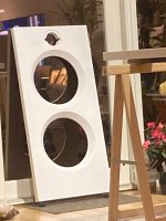
@housemd Could you share your crossover? I also am busy building a copy of the Caladan's and I want to make the crossovers exactly like the originals but the value of the parallel choke coil of the tweeter is missing. The Jantzen Cross Caps are 20uF both for the woofers and tweeter (parallel to the tweeters 20uF cap there is a Jupiter Copper foil beeswax 0.22uF 400v condenser), the series choke coil of the woofers is a Jantzen 7mH. I think the Choke for the Tweeter is adjusted to somewhere between 0.75mH and 1.3mH depending on the resonance frequency of the tweeter. I bought 2 tweeters Dayton Audio tweeters as mentioned above, their resonance frequency differ a lot, one has f res. of 756Hz and the other 860Hz. Below a picture of one MDF baffle painted with a coat of primer
Attachments
Last edited:
That's the problem with Dayton Audio, their QC is all over the place and their published specs are pure fantasy.I bought 2 tweeters Dayton Audio tweeters as mentioned above, their resonance frequency differ a lot, one has f res. of 756Hz and the other 860Hz.
@kor952 I just had to register since I'm doing the same thing as you guys. I found pictures of the Caladan and X-over parts that someone posted on another forum. You seem to have a little more experience on the matter than I do and i hope you could shed a light on how everything is supposed to be wired up? Even though many give DSP high praise, I still like to have a proper passive x-over.
Also, what angle did you cut the edge of the openings on the baffle?
Here are the links to the pictures. Please share if you have any ideas or further information
https://imgpile.com/i/xoTwIW
https://imgpile.com/i/xoT5MP
https://imgpile.com/i/xoTh8j
https://imgpile.com/i/xoTRA1
https://imgpile.com/i/xoTTeL
https://imgpile.com/i/xoTdCx
First the angle, it is 45 degrees, the thickness of the baffle is 38 mm I made the 45 degree edge 28 mm deep but I think you better can stop at 25 mm, specially if you use MDF. Otherwise you you will have serious trouble with screwing the woofers to the baffle. You need to pre-drill the screws but not too big and not too small please test before drilling your baffle. The big caps are both 20uF Jantzen or Dayton Audio caps parallel to the tweeter cap there is a Jupiter cap, I bought a 0.22uF 400V but maybe the original has a different value. The aircore coils for the woofer is a 7mH Dayton Audio or Jantzen, the one for the tweeter is about 1.2mH maybe a bit larger 1.25-1.28 mH but the 1.2mH does a good job at mine. Between tweeter caps and tweeter there is a 0.51 ohm 10W resistor.
Is this al you need to know? If you need more help please ask.
Is this al you need to know? If you need more help please ask.
Thank you for sharing! And thank you for the tip about the mounting. It's always welcome to minimize any risk of error along the build. It looks like there is about a 8 - 10mm edge between the woofer and the angled part when i look at the product pictures. I asked ChatGPT, just for fun, about the recommended value of the coil for the tweeter and it suggested a 1.1mH coil, concidering the other parts and technical aspects. I'm just a novice, but seems to me that it's not that far off? Not sure exactly what the difference from 1.1mH to 1.25mH actually does sonically, but i guess there will be a difference...
Do you have any schematics of the crossover? I haven't built a crossover in at least 20 years and I am most certain that i will mess it up.
I'm very interested in how you like your speakers? Would you say that they are worth the 3000 Euro pricetag if you where in the market to buy them pre-built?
Do you have any schematics of the crossover? I haven't built a crossover in at least 20 years and I am most certain that i will mess it up.
I'm very interested in how you like your speakers? Would you say that they are worth the 3000 Euro pricetag if you where in the market to buy them pre-built?
If you search for 2nd order Linkwitz Riley filter you have the layout of the filters, use the 0.51 ohm resistor to connect the tweeter to the filter. You can calculate what will be the resonance freq. of a filter section by using the following formula: Res freq. = Sq.root (1 / (6.28² x C x L)).
Sq.root (1 / (6.28² x 20.E-6 x 1.1.E-3)) = 1073 Hz, Sq.root (1 / (6.28² x 20.E-6 x 1.25.E-3)) = 1007 Hz. My speakers are playing for a little week now, After a few days they start to settle but the sound is still changing but not as much as the first days. I also did not implement the Jupiter caps yet and I also did not mount the Gaia III feet yet. I like them very much one of the things that is realy better as my Audio Note E Sp is the intelligibility and spaciousness. Both my wife and I realy like them, $ 3000 seems to me not to much for this speaker. (My AN E's are from 1996, last autumn I repaired the foam surrounds of the woofers for the second time of the speakers life)
Sq.root (1 / (6.28² x 20.E-6 x 1.1.E-3)) = 1073 Hz, Sq.root (1 / (6.28² x 20.E-6 x 1.25.E-3)) = 1007 Hz. My speakers are playing for a little week now, After a few days they start to settle but the sound is still changing but not as much as the first days. I also did not implement the Jupiter caps yet and I also did not mount the Gaia III feet yet. I like them very much one of the things that is realy better as my Audio Note E Sp is the intelligibility and spaciousness. Both my wife and I realy like them, $ 3000 seems to me not to much for this speaker. (My AN E's are from 1996, last autumn I repaired the foam surrounds of the woofers for the second time of the speakers life)
Alright... I have spent several hours the last couple of days to wrap my head around this because i really want to learn. I feel like there is a problem in the tweeter circuit, but I have to admit that I am stuck. Eveything might be wrong. Please explain to me like I'm a child, my brain is currently on a information overload. No hard feelings, I promise 

The woofers are connected OK! ")
The tweeter..... Connect the caps in parallel not in series, The resistor must be moved completely to the right between the coil connection and the tweeter. Please inverse the polarity of the tweeter, in this drawing minus is top connection of the tweeter and connect the plus to the ground. And please change the value of the air core coil to 1.2mH maybe even 1.25mH.
Hope it is clear now otherwise ask again!
I made changes and there was a huge benefit on the response curve! How does it look now?
Now I only have two questions.
1. Why inverse the polarity on the tweeter? What does it acutally do?
2. How come the coils should be in parallel at the tweeter nut in series at the woofer?
Thank's for your patience!

Now I only have two questions.
1. Why inverse the polarity on the tweeter? What does it acutally do?
2. How come the coils should be in parallel at the tweeter nut in series at the woofer?
Thank's for your patience!
Closer, but still not quite correct…
Your woofer circuit is good. Leave that alone.
To answer your questions,
1) In a 2nd order L-R, it needs to be inverted for proper operation, im sure somebody can answer it better, but in the time being, just invert the tweeter.
2) The tweeter circuit is a “high-pass” filter, meaning it blocks the bass. The woofer circuit is a “low-pass” filter, blocking the treble. Because of this, the reactive components (capacitor and inductor) need to be arranged in an opposite manner on the woofer in comparison to the tweeter, as they have opposite functions.
The general arrangement should look like this -

Also, you need to parallel both the tweeter capacitors to eachother, but then arrange that assembly in series to the tweeter before the tweeter’s inductor.
Your woofer circuit is good. Leave that alone.
To answer your questions,
1) In a 2nd order L-R, it needs to be inverted for proper operation, im sure somebody can answer it better, but in the time being, just invert the tweeter.
2) The tweeter circuit is a “high-pass” filter, meaning it blocks the bass. The woofer circuit is a “low-pass” filter, blocking the treble. Because of this, the reactive components (capacitor and inductor) need to be arranged in an opposite manner on the woofer in comparison to the tweeter, as they have opposite functions.
The general arrangement should look like this -
Also, you need to parallel both the tweeter capacitors to eachother, but then arrange that assembly in series to the tweeter before the tweeter’s inductor.
- Home
- Loudspeakers
- Multi-Way
- Caladan by Clayton Shaw DIY