A couple questions on Solid State PT to be used on Tube amp

Hello all,

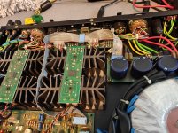
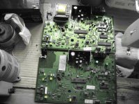
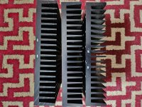
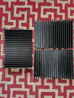
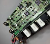
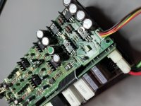
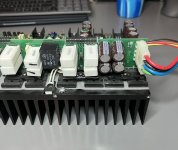
I recently bought a transformer that had formerly been in a Sony STR-DH190 solid state receiver. The specs say that this receiver was capable of about 100 watts per channel. It's quite large and heavy. I've read online that these transformers can be repurposed as PT for lower-voltage tube amps, given that their secondaries are frequently rated in amps as opposed to milliamps. Some have even argued for using voltage doublers, which I've done myself in a different tube amp; it worked fine.

2024-06-15 09.46.25.jpg


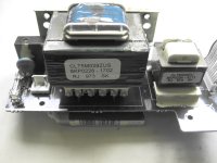
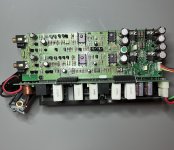
The PT has a pair of primary wires and two sets of secondaries. One is a set of five thin wires, divided into 2 and 3 (center tapped). The second is a set of five larger wires, with one center tap for the remaining four wires.

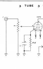
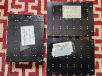
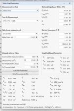
I measured the primary resistance at 1.6 ohms. The secondaries all measured between 1 ohm and .3 ohms, as shown in my pencil drawing.

I put a 24 volt (no-load was 28 volt) AC transformer on the primaries and measured the secondaries. Then I applied a factor of 4.35 to get to what the approximate no-load voltage would be at 122 VAC.

The smaller secondary pair is 8VAC. The center-tapped smaller secondary is 21.83 VCT. The larger secondary is 65VCT and 89VCT.

So here's my question. I was playing around with a pair of 32L7GT tubes. They are combined rectifer/beam power tetrode. They need 32.5 volts on the heaters at .3 amp, and 90 volts on the plates and screen, drawing a combined 29ma per tube.

I was thinking I could derive my heater voltage from the 65 VCT secondary running the heaters in parallel, and then get my (approximately) 90 volts from the 89VCT secondary. However, I don't know if you can or should take power from both legs of a single center-tapped secondary; I've never done that before. I was thinking I could use the smaller secondary's 8 VAC output to run a solid-state pre to feed the tube input.

I realize this is all an exercise in WTF, but I'm just playing around for fun. Can I get away with it?

2024-06-15 09.46.36.jpg

Suggestions for a Full Range Driver with Moderate Xmax?

Hi all,

Browsing around, just looking at options. I like full range drivers and the sound, even whizzer cones. I'm curious about what options anyone can suggest for any size driver with moderate xmax. Something greater than 4mm basically I guess I should say. Not expecting crazy, but something closer to 6~7mm real world excursion capability? Mainly looking for something that would do well in a fairly larger volume bass reflex tuned down to say 40~60hz, mainly closer to the 60hz side, but I would absolutely entertain something that could do a 40hz range even.

I'm been looking at Mark Audio, Fostex, Lii, Seas, etc, on Madisound and a few others places. But is there anything else suggested? Not looking to go too exotic in the several-thousand dollar range. But anything fun in the $300~400 or less range would be open for playing around with a build. It would be used with active DSP to be able to EQ things as needed.

Currently using a pair of Visiton BG20's, 8" with whizzer cones in sealed cabinets. I'm going to re-do them in a bass reflex around 1.5 ft^3 tuned closer to 50hz I think. But before I do it, I'm curious if there are some other drivers that would be better at this. Use is music only. Not trying to be super loud. Will couple with a subwoofer. But I like low crossovers, so I'm trying to get down to 60hz or so before I need to integrate a sub.

Very best,
  • Like
Reactions: Lawnboy

For Sale TangBand 3" Dome Midrange 75-1558SE - Unused

6 pieces of Tang Band 3" dome midrange original edition 75-1558SE. These are all from before they stopped production.

I'm asking £100 GBP each + P&P. I'm in the UK but can ship anywhere you like. They are $180 USD on Parts Express.

Lots of Photos HERE

20240527_142932.jpg

20240527_141504.jpg


Additional Measurments at Hi-Fi Compass.

I have measured them to ensure they are all working properly.

Two of these (Sample 1 and 2) were built by the by the "master engineer" at TangBand. The others were purchased from Parts Express.

Based on the response below (separated 10dB for clarity) I would pair match:

S1 and S2
S3 and S6
S4 and S5

Individual responses measured at 2.83V @ 20cm

1716757474331.png


1716755644611.png


1716755685199.png


1716756685917.png


1716755777754.png


1716755802417.png


1716755835514.png

CCL0130 and CCLH100 _ is there anything that can do the same job in a circuit ?

Hi ! in another thread i saw a very interesting circuit The one here below Dont consider the writings

1718095556294.png


are there parts than can replace the current limiting diodes CCL 0130 and CCLH100 and do the same job ?
if i understand well this circuit should work very nicely as unity gain buffer
The diodes are not very easy to source What could be used instead ?
thank you very much indeed and have a nice day

Balanced audio summing mixer

Hi!

I'm looking for a way to mix two balanced audio stereo signals. I've got two PCs right now, and I'd like to be able to connect and listen to both at the same time from a single amp without switching between inputs.

I can find plenty of passive SE summing mixers, but I can find none for balanced audio that also have volume control built in.

Before I wandered over to the DIY section, I wanted to see if anyone here knew of existing solutions that would work with no extra DIY work.

Thanks!

For Sale Svetlana 6D22S half-wave rectifier tubes

For sales 21 pieces Svetlana 6D22S half-wave rectifier tubes. Tubes from 12 / 1991 (18) and 10 / 1989 and 2 original packing
Russian damper Diode 6D22S. the 6D22S is similar to EY500. All from Svetlana factory.

Filament voltage: 6V Heater current: 1.75 A
Anode Current average: 300 mA Anode pulse (Ua = 50 V): 1000 mAh Reverse voltage anode pulse: 6 kV

They are designed for quite high currents; a pair delivers 300 mA continuous current at 1 kV or more. It is important to note that the cap is connected to the cathode, NOT the plate.

The 6D22S can also be used in bridges. You have to pay attention to the insulation values of the filaments.

Asking for 120€ for all Tubes shipping is not included

The 6D22S can be shipped worldwide with Germans DHL plus 5% PayPal fees. Registered Parcel only.

Attachments

  • Diode 6D22S (1).jpg
    Diode 6D22S (1).jpg
    229.1 KB · Views: 49
  • Diode 6D22S (2).jpg
    Diode 6D22S (2).jpg
    251.6 KB · Views: 44
  • Diode 6D22S (3).jpg
    Diode 6D22S (3).jpg
    189.4 KB · Views: 43
  • Diode 6D22S (4).jpg
    Diode 6D22S (4).jpg
    275.8 KB · Views: 48
  • Diode 6D22S (5).jpg
    Diode 6D22S (5).jpg
    154.3 KB · Views: 46
  • Diode 6D22S (6).jpg
    Diode 6D22S (6).jpg
    134.1 KB · Views: 48
  • Diode 6D22S (7).jpg
    Diode 6D22S (7).jpg
    280.5 KB · Views: 51

Design of C-core nanocrystalline GM-70 output transformer

Hi,

I'm trying to desing single ended GM-70 output transformer using nanocrystalline C-cores and I need some help because this is my first approach to OPTs.

Design assumptions:
  • core: double nanocrystaline C type cut core (same size as AMCC-400) per OPT
    nanocrystalline material annealed in transverse magnetic field (the most narrow and linear B-H loop)
    Bmax=1.25T
  • single center custom FR-4 bobbin
  • 30W, anode current up to 100mA
  • using OPT_da desing tool
  • winding with numeric winding machine
  • OCC copper for windings (not for prototypes ofcourse)
  • Nomex insulation (also in final version)
  • for first try only 8Ohm output

Newbe ideas:
  • number of turns in sections - an integer multiple of turns of single layer (to keep windings smooth)
  • 17 sections (9 primaries in series and 8 secondaries in parallel)

My first attempt:


OPT_da_1.JPG


Questions:
  • does it make any sense? 🤔
  • Fo=30Khz seems to be low?
  • bobbin is filled only in 50% (16,6 of 35mm) - is it a problem?
  • should I be concerned about calculated resonant freq of primaries/secondaries?
primary:
OPT_da_1a.JPG

secondary:
OPT_da_1b.JPG


Project files in attachement.

Thanks for any help.
Marek

Attachments

For Sale Toshiba 2SK117GR & 2SK117BL

for sale 260 pieces 2SK117GR and 200 pieces 2SK117BL - all Fets are 100%. I bought from German Toshiba distributor Spoerle electronic. As you can see in the pictures, the 200 pieces 2SK117GR (2.6-6.5mA Idss) are still in the original blue packaging from Toshiba.

Two of the Toshiba 2SK117GR are equal to one 2SK170BL with slightly higher amplification, with lower capacitance and also with lower resistance. Minimum order 20 pieces for 65€.

The Fets can be sell worldwide with Finnlands Posti or Germans DHL plus 5% PayPal fees. Registered Parcel only.

Attachments

  • 2SK117GR, & 2SK117BL (1).jpg
    2SK117GR, & 2SK117BL (1).jpg
    169.7 KB · Views: 77
  • 2SK117GR, & 2SK117BL (2).jpg
    2SK117GR, & 2SK117BL (2).jpg
    465.2 KB · Views: 87
  • 2SK117GR, & 2SK117BL (3).jpg
    2SK117GR, & 2SK117BL (3).jpg
    259.9 KB · Views: 82
  • 2SK117GR, & 2SK117BL (4).jpg
    2SK117GR, & 2SK117BL (4).jpg
    150.7 KB · Views: 74
  • 2SK117GR, & 2SK117BL (5).jpg
    2SK117GR, & 2SK117BL (5).jpg
    224.3 KB · Views: 73
  • 2SK117GR, & 2SK117BL (6).jpg
    2SK117GR, & 2SK117BL (6).jpg
    219.7 KB · Views: 74
  • 2SK117GR, & 2SK117BL (7).jpg
    2SK117GR, & 2SK117BL (7).jpg
    165.6 KB · Views: 76

Onkyo M5060 R

Hi all,

I am having some trouble with my Onkyo M5060 r.

I use it in pair with its P3060 pre amp.
I am running a pair of JLB4311.

From time to time, the amp will turn red (from.the operational green) and will go in protection mode. I believe.

I am not sure on the cause.
One channel will go with a brum in it....

Can anyone help me out, hold my habd type of, and walk me through a diy attempt at repairing it?

I used to love changing a diode, transistor here and there in the past. So I am not that atehnical. But I will struggle for something this advanced.

Anyone that wants to embark on this newbie challenge please know...you will dictate the pace. I can't afford to have demands to finish it in 2 days type. You're the lead and I am the apprentice.

Thanks in advance.
I do have my soldering kit, my multimeter and the schematics.

NAD 3130 low level switch clicking when depressed/released

morning-
i wonder if i any of you guys have an opinion on something ive tried resolving many times without any success, and this is a common problem with these units

The low level switch clicks when depressed
now i have taken them out, stripped them down and cleaned them, swapped them with others, ive even tried replacing the 2 muting FETS and the resistors in the circuit, but to no end, so i just wondered if you had any thoughts on it
Ive been all over the muting circuit and low level switch, and can find no evidence of noise with the scope, other than the scope changes very slightly(jumps) when the switch is depressed.

Its more anyoying than anything because i cant find it and have this on 90% of the units ive had though my hands, and now i want to find it once and for all.

cheers

paul.

Attachments

  • 3130 click.jpg
    3130 click.jpg
    177.2 KB · Views: 102

HammerTech LCA 600.1 not oscillating

Hello everyone,

Recently, I received a HammerTech 600.1 class D amplifier with a dead output section. Upon further inspection, I found that two of the buffer transistors were dead as well, so I replaced them with new working parts. Two marked resistors also appeared to have been drawing a lot of current, so I replaced them too.

Everything now checks out okay in and out of the circuit, but there is no oscillation on the outputs, and the amplifier turns on normally without going into protection.
Also removing those two marked zeners will result in some oscillation but it's not fully forming the pwm signal and sounds very distorted.
sketch-1717584080671.png


Can anyone be kind enough to help me find out what the problem is?

Thanks in advance.
IMG_20240605_014719.jpg
sketch-1717583351954.png
sketch-1717583376039.png

Hi everyone! - Question about Monsoon computer speaker

Hi Folks,

Just joined this forum last night.

Apparently I'm 20+ years late to the Monsoon computer speakers party! Found at Goodwill for $8.49 a Monsoon MH-505 speaker system, missing power supply and rear speakers. They looked 'cool' so I decided to take the chance and bought them.

Once home I decided to by-pass the sub (since I didn't have power for it anyway) and cut the RCA plugs off the front speakers and connected them to my FosiAudio BT20A amp. Then, plugged the amp into my old DragonFly Black USB DAC and fired up Spotify. Played an old fav, Holy Cole's "Invitation to the Blues" WOW - imaging and clarity was stunning - totally want to know more about Planar! Spent the next two nights Googling Monsoon.

My main focus is to keep these as computer speakers, focusing on music, NOT games.

Have a few questions, if anyone would be willing to share? Please keep in mind I'm a total noob compared to most folks on this site, sorry... Also, family life forces me to stay under $300 budget. 🙁

1) The 3" cone woofer seems a bit 'weak' - can they upgraded fairly easily and cheaply (ie for less than $100)? Is this complicated by an internal cross-over in the front speakers or just a simple replacement in existing enclosures and circuitry? I found on another forum someone stating they were upgrading them using Peerless PLS-P830985 or Dayton Audio PC83-4. Would this be a big sound improvement.

2) I've read the MH-505 sub is 'okay', but not great. Got power supply for sub today and hooked things up skipping the FosiAudio BT20A amp... sound stage compressed and everything was much 'thinner' sounding... not sure if that's expected or if the amp is bad in the Sub... I've seen a few posts where folks use other subs but most don't allow cross-over above 180Hz, which is still too low for the front speakers.

How about this, (from another forum), use Dayton Audio DSP-408 4x8 DSP and a BESTIAN Powered 6.5" Home subwoofer. I'd still use the FosiAudio BT20A to power fronts.

3) Would a later model 'Monsoon PlanarMedia 14' system (if I could find one in good shape) be better sounding with later planar panels and skip trying to customize the MH-505's

Any suggestions greatly appreciated!

Thanks!

Why do a lot of songs from around 1972-1973 have a unique sound to them, while other periods dont?

I've noticed that A LOT of songs from the ~1973 time have a certain... warm, low pass sound to them. Was there some unique piece of gear used at that time? I don't hear that in music from any other period...
Some examples:
Browning Bryant - Blinded by love, 1973: https://inv.n8pjl.ca/watch?v=Clz6fXwTOs4
Vincent - Don McLean, 1972: https://inv.n8pjl.ca/watch?v=ajX26nIYpUE
Marc Benno and the Nightcrawlers - Coffee Cup, 1973: https://inv.n8pjl.ca/watch?v=Ck6YKqfL3y0

And when trying to compare songs from that period, it's hard to tell what "the sound" I'm hearing is, but whenever I hear a new song with "that sound" I instantly think it's 1973, which it always has turned out that it indeed is.
The odd thing is it's not just american records, it's also songs from the UK.
  • Like
Reactions: Juhazi

For Sale Focusrite Scarlett Solo 2nd Gen

I bought this several years ago to test THD of some circuits, but only rarely used it since I've basically stopped building new things. Includes original USB cable and box. I wasn't interested in using the included software, so have not registered the Solo, which should mean that the software is available for whomever buys this.

Asking $50 plus actual shipping to your location. Payment by PayPal. SOLD

20240325_113958.jpg

For Sale Heatsinks

Looking to get rid of some heatsinks that I no longer expect to use. PayPal is probably easiest for payment. Will ship within the US at buyer's expense. The heatsinks all fit into a medium flat rate USPS Priority Mail box, so can ship for $18.40. Other carriers can be considered at your request, but they are unlikely to be cheaper. Will consider shipping to other counties, but this is likely to be expensive. Local pickup in western Illinois is also a possibility, as is meeting part way if schedules line up to allow travel.

Three black anodized heatsinks which have a grid of holes drilled and tapped in the base. Some scuffs and fins on the sinks. Each sink measures about 7.875" wide, 5.875" high, 1.5" deep with a 0.375" thick base, so the fins are about 1.125" tall. Each sink weighs about 3.5 pounds. I've tested these at about 30W dissipation per sink with comfortable temperature rise. Asking $20 for all three. SOLD

Note that measurements are rounded to the nearest 0.125" for simplicity and weights are approximate as my scale's accuracy is questionable.

Attachments

  • 20230713_132642.jpg
    20230713_132642.jpg
    542 KB · Views: 311
  • 20230713_132619.jpg
    20230713_132619.jpg
    510.8 KB · Views: 300
  • 20230713_132559.jpg
    20230713_132559.jpg
    796.6 KB · Views: 310

Anthem PVA-7 - Strange Oscillation

Amp is FIXED!!!!! - see Post #54-57 for the specifics of the repair.

I bought a used PVA-7, knowing that it might have some problems. Powered up on the DBT, 60w, 75w, 150w - no issues. Checked for DC on all the outputs - none were higher than 20mV. So I moved to testing with an 8r dummy load resistors, still on DBT with no issues. Took the amp off the DBT and tested with 500Hz and 1000Hz sine waves into the 8r dummy loads up to about 50% power - again no issues.

Here is where it gets weird - connected the amplifier to some low-grade speakers for initial test. At low volumes on sine wave or music (~<1w) it sounds okay and will play. As soon as you turn up the volume on sine wave or music to 2-3w, the bias jumps up from 15mV to close to 1V and the 10r output (zobel) resistor heats up and the amplifier shuts down, protection circuit kicks in This oscillation/overheating takes about 3-5 seconds to kick-in the protection, depending on how much you turn up the volume.

I tried the same test with only the faulty channels (2 channels on a single heatsink) on DBT and will play fine up to 27Vac (max preamp volume) on the speaker outputs as long as it's playing into an 8r dummy load. As soon as I connect my speakers (~6.7r nominal load) it will cut out at around 75% volume and you can see the current ramp-up in the DBT. As the DBT lights up, so does the 10r resistor on the output.

Final test was to try each channel separately and it appears it is only on one channel, I can hook up the other channel to the speaker and play as loud as I want with no issue. I can connect to the 8r dummy load on faulty channel and still plays up to 75% before protection. But a speaker on the faulty channel or both channels hooked up to speakers and it shuts down quickly.

Amplifier board: I have tested all TO-92, pre-drivers, drivers and outputs to the working channel and everything checks out. Measured every resistor and diode going bad board to good board and they all measure within 1-2%. Output BJTs measure good and no DC on the output - so I'm at a loss to why the amplifier is oscillating.

Also - nothing except a 2N5551 has been changed in the relay circuit. Measured a little low on Hfe, so I changed it out. Everything else, including solder joints all look original - not been touched.

Can this be capacitors? I know typically you would add, change or revise capacitors in the circuit to kill the oscillation, but since this is totally stock, could it be a bad capacitor in the circuit causing the oscillation?

Attachments

  • IMG_7214.JPG
    IMG_7214.JPG
    598.1 KB · Views: 182
  • IMG_7215.JPG
    IMG_7215.JPG
    553 KB · Views: 166
  • IMG_7216.JPG
    IMG_7216.JPG
    428.7 KB · Views: 189
  • IMG_7217.JPG
    IMG_7217.JPG
    447.1 KB · Views: 166
  • IMG_7218.JPG
    IMG_7218.JPG
    454.1 KB · Views: 167

Quad 12L Active Monitor schematics?

Hi Folks, I'm looking for the schematics of the Quad 12L Studio Active monitor. One of mine has developed an intermittent crackling noise, that I want to track down and fix. I've posted this in the chip amp section, as I know these things use a pair of chip amps! I can probably reverse engineer them, and will if necessary, but thought I'd see if I can save myself the trouble... Thanks in advance! Dave

Help with a Peerless SLS 8

I am having trouble with my Peerless SLS 8 for my 3 way. I have taken actual theile small parameters using REW. When I enter those into WINISD I always end up with a weird hump. Stock parameters for the Peerless SLS 8 is dead flat. I will show the parameters, the graphs, and the box.

Does someone know of anything I can do to fix this? I planned on crossing it over at 300hz but I fear I will end up with an odd dip between 80-200 hz.
Stock line is red, actual measured theile paramters is pink.

Attachments

  • sls thiele.png
    sls thiele.png
    27.2 KB · Views: 68
  • Screenshot 2024-06-11 135628.png
    Screenshot 2024-06-11 135628.png
    38.9 KB · Views: 70

ST1000a, aligning the FM alignment tool

I am making progress fixing and "calibrating" this classic calibrator.

20240615_061313[1].jpg
Backstory:
(or skip down to the maroon coloured text to see my concerns/issues}

I am attempting to rehab a 70's FM tuner (Luxman t110u).
So, I found this dusty Sound Technology ST1000A at my local surplus dealer - no fuse holder, loose switches, unknown functionality.... $100.
At my bench, I fixed the fuse and decided to replace the main PSU filter caps. Good thing, because one of them was bad and had turned into a wayward resistor.
(they were 1500uf each rail, but I went for 2000uf each.)

20240615_063802[1].jpg
Then, through an ammeter, I plugged it in to my variable AC transformer, flipped the ST1000a power switch and slowly turned the voltage up to 120v ...keeping a close eye that the ammeter did not spike.
All seemed ok, and it showed signs of life.
After a long sleep, it curiously opened it's dusty eyes.

I cleaned and lubed the rotary switches. The carbon pots did not seem to need attention. The meter reacted as if it was new.
I began to replace the smaller axial electrolytic caps on the internal board, but every cap I removed tested like new, so I stopped replacing them, for now. Those old Sprague 30D types seem pretty robust !
This must be an early unit, because it includes Opt, M-2, but not with the typical 1k/400hz switch.
Instead, it has 4k/400hz. Curious.

20240615_064104[1].jpg

The manual/service guide is easily found online, and here...... http://www.stancurtis.com/soundtech.htm
An article on "updating/upgrading" the ST1000a is here..... http://www.ham-radio.com/k6sti/st-1000a.htm

Following the adjustments outlined the manual, the ST1000a was close to specs, but everything needed a little tweaking to become spot-on.
I performed one upgrade from the above article, to lower the distortion of the internal wein-bridge oscillator (added two resistors and a cap).
Using my QA403 audio distortion analyzer, before the mod :
3862 Hz (4 kHz) = .027 %THD
393 Hz (400 Hz) = .017 %THD
...after the mod:
3862 Hz (4 kHz) = .0008 %THD
393 Hz (400 Hz) = .0006 %THD

Other adjustment steps from the manual:

152 kHz/19 kHz Crystal oscillator adj.... (C20) adjusted to within 10hz, good.

R/L Gain Balance (38kHz Carrier Suppression) (R1, R7) One trim pot minimizes the 38khz ripple from the upper half of the (sine) waveform, another trimmer does the same to the lower half of the waveform. I think I did it correctly, making both halves of the sinusoidal wave show as little ripple as possible. I can still see a little ripple, but just barely.

DC balance. (R19) Trim to get lowest DC millivolts (less than 20mV) I trimmed to 5mV.

Mono/Stereo Sub-channel Separation. (R35, R38) Here, the guide is confusing. I don't feel confident that I am adjusting correctly.. or to what is wanted.
The drawings are rather vague ?
20240615_082954[1].jpg
I tried Method A and Method B.
Method A, I think I'm trying to get the flattest line across the center ?
Method B, I think I'm trying to get the "cusps" close, but not touching ?

Here are my adjustments, and a pic of the overload-preventing clipping diodes, per the manual instructions:

20240614_215546[1].jpg20240614_215947[1].jpg
20240615_082558[1].jpg

FM Modulator Linearity. (trimmer R52) In this step, I do not have the gear shown in the drawing.
HP 5210a Discriminator
HP 10534a Double Balanced Mixer (50k to 150mHz)

20240615_063825[1].jpg

The 5210a discriminator...guessing this gives you the difference between two frequencies ??
I think I can do that with my counters, including phase differences ?
20240614_224040[1].jpg
The HP 10534a passive mixer....I have one of these (Clarke Hess "active" mixer) but I'm not sure if will work, or if it has enough bandwidth , I've been looking for it's rare manual.
20240614_224050[1].jpg

Modulator Level (trimmers R47, R95) This is to be done after the above Linearity step, so I can't proceed before the Linearity adjustment.
The manual gives a method using an accurate Standard Generator, OR a method for using a Discriminator.

Internal Oscillator (distortion adjustment, R105, R95) I did that, as noted earlier.
Pilot Phase. (R93) not adjusted yet.
L/R Balance (R118) not adjusted yet.
RF Stereo Separation (C16 trimmer) not adjusted yet.

END OF ADJUSTMENTS.

BTW, I built the "ST Model 100" 50 ohm to 300 ohm adapter, as noted from the links above....
20240615_064006[1].jpg

VTL Compact100 Monoblock Blows Fuse

A buddy has a pair of VTL Compact 100 Monoblocks (circa 1988) that have performed well, He recently retubed & reset bias with good initial results. Several weeks later one of the pair began blowing mains fuse. I have SS experience but am a newbie at tubes - my first thought given the age was to replace electrolytic capacitors & check tube associated resistors as well as solder joints & socket to tube pin contact. Am I on the right track or are there other obvious items - also if anyone has a schematic that would be very helpful. Thanks!😉

Seeking Advice for Unwinding an Inductor

The crossover for Dennis Murphy’s CAOW1 2-way speaker design calls for a 0.06 mH inductor with a 0.10 ohm DCR. In his write-up Dennis indicates “You will probably have to order a 0.10 mH inductor and unwind a little less than half of the wire. The value is not critical.”

Dennis Murphy's CAOW1

Dennis is correct so I have some questions about how to arrive at 0.06mH from a 0.10mH inductor, or at least close enough to work:

1. Can I weigh the coil on a digital scale then unwind and remove material bit-by-bit until the coil weighs 60% of the original value? The only thing I would be measuring here is weight of the coil.

2. Would it be better to purchase an LCR meter to measure inductance as I unwind, or is this overkill considering Dennis’ saying the value is not critical?

3. In general, do most people verify the accuracy of other crossover components or trust the manufacturer’s values? If most verify other components I may get an LCR meter to check resistors and capacitors in addition to getting really close with the inductor.

Peak LCR Meter

Thanks in advance for your advice!

Attachments

For Sale XRK BTSB Audio Buffer Board + Discrete Diamond Buffer Bundle

SOLD
A set of XRK Audio BTSB THT buffer board for sale.
A very convenient front end board with good connectivity flexibility, and gain selection by means of dip switches.
More details are here :
https://www.diyaudio.com/community/threads/btsb-buffer-se-bal-to-se-bal-buffer-gb.358142/
My board happens to be the version with a slight error as mentioned in the thread above.
Details of the error here :
https://www.diyaudio.com/community/...o-se-bal-buffer-gb.358142/page-3#post-6330962
A simple change of resistor position would correct this error, and this correction has been done on the board i am selling.
I used an off board bipolar psu for this board and hence did not populate the Murata isolated DCDC. Wires has been jumpered to the connector for +/-15Vdc inputs.

I will also throw in a set of discrete diamond buffer i received from the giveaway from XRK Audio. The default giveaway boards has 'wrong' led on them. I have changed to the 'correct' led part recommended by XRK Audio. They have been tested and working properly. I paid shipping from US to Singapore for these boards. Details of board here:
https://www.diyaudio.com/community/threads/xmas-diamond-buffer-giveaway.405895/
https://www.diyaudio.com/community/threads/jhoflands-diamond-buffer.401231/#post-7522644


The set of BTSB + Diamond buffers + shipping registered & tracking = 95 USD
Paypal FF Only please.

Attachments

  • 20240511_113026.jpg
    20240511_113026.jpg
    504.2 KB · Views: 165
  • 20240511_113048.jpg
    20240511_113048.jpg
    495.4 KB · Views: 183
  • 20240511_143633.jpg
    20240511_143633.jpg
    542.7 KB · Views: 174

For Sale SEAS W22EX001 8ohm, SEAS Prestige 27TBCD/GB-DXT H1499-06 Tweeter

Pair of SEAS Prestige 27TBCD/GB-DXT H1499-06 Tweeter. Gently used, work great. $200 + $10 shipping.

SOLD Pair of SEAS W22EX001 8ohm woofers. 8" magnesium cones. Used, not abused. Not original boxes but will be well packaged.

All were used in an active XO 2 way config.

Attachments

  • 20231001_123214.jpg
    20231001_123214.jpg
    511.1 KB · Views: 95
  • 20231001_123143.jpg
    20231001_123143.jpg
    639 KB · Views: 114
  • 20231001_122901.jpg
    20231001_122901.jpg
    580 KB · Views: 109
  • 20231001_122847.jpg
    20231001_122847.jpg
    631.9 KB · Views: 111

Shunt type volume control for tube preamp

General consensus from what I read is that a straight log pot of good quality is better than any shunt arrangement. So no doubt several replies will confirm this. Downside is that good quality pots, especially stepped attenuators, are expensive.

But supposing, in the interests of economy, you did construct a shunt control for a valve amp or preamp, what is the best you can do? Here we assume a typical DAC input of low output impedance which would be happy into 10K. So I'm assuming that theoretically the shunt resistor should be 10K or more, but please dispute this.

I've made an experimental external box to try out different resistor values. Shunt resistors for first trial are old style black Holco 1W. Pot is 50K log chi-fi Alps. This feeds an amp with a 100K resistor to ground on the input. Results....

38K shunt - law is fine but too much attenuation of the signal
10K shunt - louder and the law is actually quite good.

These are very audibly inferior to a simple 100K Holco input resistor to ground and volume control in software on my Mac Pro with lossless tracks in iTunes.

Please suggest anything that will give better results......

Capacitors test expertise

Hello,

I have few caps

Audyn QS6, Qtext4​

not tested by anyone yet, no reviews at all conducted.
I'm looking for somebody with the expertise and experience willing to do tests and share his impressions.
I'll supply the caps, but based on latest Canadian postage rates, shipping is quite unaffordable/reasonable in comparison to the cost of the caps and else..
Thus I'm looking for somebody in Calgary ( a long shot) and surrounds in order to avoid the shipping charges.
Any other suggestions, please?
Thx

MSB DAC I2S pro format

Dear Sir,


My friend has a MSB DAC which has RJ45 input called I2S pro. DAC feedback the clock to MSB transport. for the rest of the pin should be I2S signal.

Any one know how to connect the another I2S device to MSB I2S pro.

For example, I have philips CDM4 transport which has HDMI and RJ45.


If I know the pin assignment of MSB DAC RJ45. I can make the connection to MSB DAC

slowmotion video project: imploding lighbulbs and tubes

The beauty of destroying lightbulbs and tubes in slow motion

I worked on this film for over a year, with new ideas coming up over time. The slow-motions were recorded with two older Samsung S9 and S10 smartphones, which offer a video function for this. The cameras only record for a period of 0.2s and 0.4s, whereby the triggering of the shutter release is done by movement in the image. Almost 1000 frames per second are recorded (960fps). The sequence is correspondingly short. Despite this limitation, I have lost practically no recording, which is irretrievable in scenes with more material use, such as with the picture tubes. Someone will ask, "Why is it still running so fast, slow motion has to run even slower?" The challenge was to deliver a maximum result with this minimal amount of equipment. On the other hand, the film consists of a lot of individual shots, all of which I want to show. If you were to shoot them with much more time dilation, the film would not last 7 minutes, but maybe half an hour. My intention was to put the dynamics and action in the foreground - you should see how it shreds! 😀

Login to view embedded media

TSA1701 loud cracking noise

Hello,

I'm experiencing a peculiar issue with my audio setup and would appreciate any insights or suggestions you might have regarding the TSA1701 DSP. Here's the situation:

I have two 15-inch subwoofers that are functioning correctly. However, when I connect a third amplifier to the system, there's no sound output—only a loud cracking noise (as shown in a video I have). I've checked to see if the DSP (Digital Signal Processor) is the problem, but the same issue occurs with a second TSA1701 DSP unit.

The problem does not seem to be related to the tweeter or the third amplifier. It arises as soon as I plug the jack into LineOut2. If I only have LineOut2 connected with two loads and then add the third load to LineOut1, the same issue occurs.

I've also ruled out the possibility of the DSP's USB power supply being too weak, as I've tried powering it with 10V directly at the socket. All individual components (2 subwoofers, 1 tweeter, 3 amplifiers) work fine on their own, but the DSP starts acting up as soon as both jacks are plugged in.

Additionally, the cracking noise gets louder when I increase the input volume.

I also tried connecting the tweeter to one of the subwoofer amplifiers, and then one subwoofer and the tweeter played perfectly. However, when I added the second subwoofer, the cracking noise returned.

One thing i thought of, is that because the DSP does have 2 3.5mm output jacks, i used 2 3.5 to RCA Cables. Because i only need one output of the second cable i just cut of the other line. Could it be possible that the error is resulting becuase of this? Should i short the wire i cut, or solder a resistor in between?

Is there any other setting or property of the DSP i have to take care of?

Thank you in advance!

My Setup:
TinySine TSA1701
Hypex SMPS400A400
3* IRS2092 500W ClassD Amp
2* the box 15LB075-UW4 15"
1* Master Audio DR8
t.mix 201 USB Play for Audio Input

Attachments

  • WhatsApp Video 2024-05-23 at 16.28.24.mp4
    3.2 MB

Hello, I'm Thomas!

Hi, I'm Thomas from Austria.
Last year I graduated from a technical college (HTL) in the branch Electrical Engineering - Smart Systems. Starting this fall, I will be studying computer science at the Vienna University of Technology.
Already during my time at HTL we created some DIY audio projects, among other things by designing and producing our own Class-D amplifier boards, and then used them in a portable active speaker.

I am looking forward to participating in some of your contributions and hope for your help in some areas.

Thanks, Thomas!
  • Like
Reactions: krivium

Crown XLS-402 attempted fix made it worse

Greetings. Attempted to repair my XLS-402 which had very low output on one channel. In a moment of brain fade I attempted to clip my scope ground to one of the driver transistor (MJE15032/033) heatsinks, thinking it would be 0V but instead got a wakeup call with a bang and a flash. I was aware the output transistor heatsinks were live I just stupidly didn't test the smaller heatsinks first before looking for a convenient scope ground. Replaced all the MJE but no output at all in either channel now. There is 95VDC on the output heatsinks but nothing on the driver sinks, I assume there was before given the fireworks from shorting it out. Schematic shows these are all connected together, any thoughts out there on why this might be the case?

Cheers

HH VX150 Crippled by VCA cards.

I have a VX150 here. I used to have three of them years ago but sold them. This one had the VCA input cards.

I have recapped this unit as the caps on the main board were going high esr and low capacitance. I stupidly put in 10uF cap in the feedback path on each channel! Of course when I tested frequency response it was down 3db at 20Hz! Anyway, I installed 100uf and then was fine.

I'm surprised how bad the VCA input cards cripple the amplifier. Distortion figures were not that good. 0.05% at 1Khz mid power. This climbed to a very bad 4% at 30Khz!! Also I had to drive it with 5v to get full output! I pulled out the VCA boards and jumpered the links and now much better. Distortion at 1Khz is 0.0045% mid power and the same at 20Khz. Also no hiss even with headphones.

Bias, DC offset and CMR adjusted to spec.

Attachments

  • IMG20240613170024.jpg
    IMG20240613170024.jpg
    222.1 KB · Views: 93
  • IMG20240613165522.jpg
    IMG20240613165522.jpg
    231 KB · Views: 87
  • IMG20240613165524.jpg
    IMG20240613165524.jpg
    304.4 KB · Views: 89
  • IMG20240613165529.jpg
    IMG20240613165529.jpg
    224 KB · Views: 100

UPV Service Manual Needed

This is why I don't like working on subwoofer amplifiers: I was working on a John Bowers Active 1 today and was not aware that the output neutral speaker line sits at -40VDC.

Usually with some McIntosh amplifiers, I have to ground the analyzer to stop the relays from clicking periodically, and I thought this was the case with this subwoofer amplifier.

It blew out something, possibly a fusible link inside my UPV audio analyzer. Now that input no longer grounds when I set analyze to 'grounded' in the menu.

I'm looking for a schematic of the input circuitry to find out where this fuse is located so I can replace as needed. At least I hope it is just a fuse and nothing more involved.

High efficiency coaxial+ low bass 3-way attempt

Having collected some promising drivers to cover from 16Hz to 20kHz, now some serious sims. Please bear in mind that due to rural regional location 1400km from Sydney, getting heavier items delivered has been problematic. A lot of times, vendors just notify with an out of stock with funds returned message

SBA and DS18 are the two brands that do send the deliveries and prices are affordable and here are some DS19 based sims including a couple of wildcards. Open to driver suggestions

This project is an attempt at shoehorning the most hardware into a cab with space constraints. Living in a tiny home makes one a bit conscious of volumes and space use. A 1cm increase in one dimension can potentially mean many more new litres. This audio project is on pocket money, channelling tobacco money to audio and recreational in nature, although I would mind making up some bespoke type parts with the digital studio and handcraft for folks when the tobacco runs out 🙂

A 50g pouch of tobacco costs over AUD $100 and the bwoy is broke after buying so much audio interest items 😀

Uses
Home cinema, when not working
Small DJ/karaoke gigs
Practice PA for a small student ensemble running synth pickups via Roland Aria MX-1 digital mixer, FL Studio with Akai FIRE control surface, Roland DJ-202 digital mixer with TR -Drums and sequencer, Roland JDXI synth that can be played with an instrument via line or mic, Yamaha MG12XU console and an electric bass guitar/double bass. Running school material through the EDM gear as extracurricular activity

SOR
Loudest full spectrum achievable within space constraints
Ability to run a flat response or Eq (onboard or external)
Electronic filters built into the system (onboard)
HT processing (onboard DTS,AC3)
Have the refining touch of bypassing the internal class d amp for the HF section and engaging an external tube amp for the tops when used at home

Config
A phantom centre based 4.1 channel satellite and sub config is appealing for not having heavy boxes up in the air. If a single LF section tests sufficient, then the 4.1 config has the added bonus of being able to fly with for tours in the home country by swapping out with a higher tuned, smaller sub cab. If a single sub is not sufficient, the cabs will be built as 3-ways with each cab featuring an HF and LF section for 4x cabs total

Primary use is HT with mostly music video and concert recording from Rototom Sunsplash type YouTube channels, streaming sites such a Netflix,. The HF sections will run of 2x 10w+10w EL43 tube power amps and a tube stage or Pass H2 inserted in the LF path. Room is 3m x 6m with three walls that can open up. This space is the open deck of a 6m custom catamaran. A bit like a pontoon boat, but not the tacky aluminium types of things that are very popular. Ours are a pair of hulls in HDPE filled with survey grade foam and tiki style wooden cosmetic finish. The walls are privacy/weather screens in wood strip and plexiglass. This vessel is under currently under construction as home DIY. It's getting built to Au maritime survey and will be rented out when not being used by us. Setting up for a working retirement with this and two other vessels, a 3.5m centre console semi GEV sports fisher and a 3.5m beach cat to deck boat conversion with deck chairs and human/electric hybrid propulsion. The location is Hervey Bay so no issues with noise pollution with being easily able to put double-digit kilometres to the next soul

Secondary use is as the mentioned PA system, with back to back pair on either side and out from the desk. To fire at the desk, any performing floor space between these wide monitors and the desk, and well to fire away from this area. School hall or someone's porch or lawn for lil DJ/karaoke type gigs. Of course the desk will also have nearfield monitors too. These are from the 'Exploring the ZR6.4D' thread in subwoofers

Our Roland and Akai pro gear will be housed in a travel case to be easily relocated to home or houseboat, as well as away trips. All the amp modules and DSP processing to be built in the speaker cabs except the tube amps which will be installed in the houseboat

So as some wind down from looking after the baby and running around all day for the family and renovations and boat builds, let's have some fun blowing up stubborn high excursion subs by winding up the power and beating up the Iron Law by taking it up to the melting point 😀

These are the drivers in contention at the moment. These have some means of environmental protection in a marine environment. Other suggestions are also very welcome. But please, apple to apples.....ok to use large format systems such as traditional PA for reference comparisons but always ask the question on how that favoured PA driver or hi-fi brand would go in these size constraints vs the SPL/response requirements. If one's fav 18" with 108dB sensitivity cant meet the SOR than the matter of fact is that it is just not good enough for the job. If a cheap and apparently looked down upon car audio gear can hit the numbers in the constraints, then they are the better drivers on the day

Constraints
10L internal is the max allowable for each driver volume for the HF sections
40L internal is the max for the LF section/sections
Smaller volumes than that would be even better

Driver pool HF
PRO-ZT69
ZXi-354
Nilspec 6.5" FR

Driver pool LF
ZR12.4D
10" DVC Unobtantium (almost half the price of the ZR12.4D)
12" DVC Wildcard, not yet acquired ($50 cheaper than the ZR12.4D)
SLC12S, not yet acquired (half the price of the ZR12.4D)
SLC10S "" (less than half price of the ZR12.4D)
SLC8S "" (well under AUD $100)
ZR6.4D, the super stubborn, super low sensitivity driver from the failed Cub Sandwich project as the near filed woofers and to compare just to get a feel of the difference in loudness levels

A side project will be to use the ZXi-354 will be used with ones of the LF drivers at an attempt at the 'high SPL. Full spectrum, 2-way' thing just out of interest

Another side project is getting one of the coaxials into a single format cab with the Unobtanium driver as a 3-way for simple travel and mixing down stereo sources to mono for use tested against the same driver with a pair of stereo ZXi-354 or 3" Tang bands again in a single box. If the ability to present a solid stereo image cannot be obtained from that, then the single coax will be kept

A single cab 3-way is needed to be in use by August, but the full development is not a rush thing and more for fun. I must mention @weltersys for helping me learn some of his lifetime of knowledge, so I may pursue this with valid data and calculations and as well for picking up on problem areas. Also @GM, Great Man, thanks for not beating around the bush and allowing me the confidence to work towards unfamiliar high SPL numbers with his direct anecdote and reflections with hands on SPL taking in his areas of use. Very grateful to these two guys
  • Like
Reactions: GM

Denon PMA-700V Amp Pot and DCD-1520 CD Player Lens Assembly parts

Hello,

I am new to the forum and joined looking for some help.
I own a set of Denon PMA-700V and Denon DCD 1520 which have been working well until two years ago.

The Denon Amp Balance potentiometer started failing and now needs replacement It is a 250K Pot.
The CD player Pickup Lens (KSS-151A) afiled and also needs replacement, preferably the whole CD Tray assembly

Is there anyone who can guide me to a source for these (Very) rare Denon spare parts?

Thanks and Regards,

Squeezebox Duet

Hi all
I found this site after my Squeezebox Duet controller stopped working 100%. I had previously had two Duet receivers fail, so I had switched to using a WiiM Mini. Much to my delight, the Duet controller continued to work with this, accessing the music stored on my NAS with Logitech Media Server running on my PC (I don't use any other streaming service). But recently, when I came back to using the system as set up, I got a "problem connecting" message: the controller could no longer connect with either my NAS or to my PC - "make sure your computer is turned on and that LMS is currently running". Well, it is (I am writing from it!) and LMS is running. On checking the diagnostics tab on LMS, I found as shown below: one of the ports had failed, while the mysqueezebox.com site was also non-functional. Further enquiry showed that it had been taken down by Logitech. I can still control the WiiM via my iPhone, but I am wondering if I can somehow resurrect the Duet controller, whose clock continues to work! and whose UI I really like! I don't understand ports very well. Can someone please advise? Thanks

Attachments

  • Screenshot 2024-06-13 131638.png
    Screenshot 2024-06-13 131638.png
    13.9 KB · Views: 84

NAD 2200pe, Unable to set the Bias.

I have been handed a NAD2200pe (serial - A 60900xxx)
It was fully recapped before it came into my hands.
I have no knowledge of its history as the current owner that handed it to me, recently bought it second hand himself.
I've fixed a lot of bad solder joints.

The below applies to both channels;
I can set the dc offsets easily to under 1mv.
Both bias's however refuses to budge from 0.1mv and the unit stays cold even after several hours of idle.
The trimpots are fine.

Any pointers would be greatly appreciated.

Attachments

Boston Acoustics Soundware S Sub Issue

Hi Folks
I have a Boston Acoustics Soundware S 5.1 speaker system. I am facing the problem of low output on my Sub in spite of keeping gain at max i can barely feel/hear the sub when playing heavy bass content audio.

The subwoofer included in this package is a 10-inch downward firing 200W RMS (Peak power of 300W) sub. Many years back this subwoofer had failed (power supply board had burnt out) and I had taken it to an authorized service center for repair. Sure, enough they did repair it and i thought it was fine, though i did complain about low Sub output. What i did not realize was that they had replaced the power supply board of my sub with one from Boston Acoustic Soundware XS model. The XS series has a 100W RMS sub. I found all this out because the sub failed again recently and when i opened it to fix it realized the board had changed. I little search on the net i realized the swapped in board was from XS model. The problem now was a burnt zener and a dry solder on a diode. Replaced the Zener and reflowed the dry solder and problem was fixed, and Sub was alive. But output level seemed to have dropped drastically.

Could the low output on my sub be because of the under-capacity Power supply board?

There are two outputs from the power supply board one for preamp and one for amp. Power for preamp/dsp given thru a 3 pin connection -20V:0:+20V and power for amp given thru a 3 pin connection -32V:0:+32V. Assuming the low sub output is because of lower capacity SMPS board I would like to replace this power supply board with a beefier one in line with the original spec, but I don't have the original board, nor can i find the service manual for the Boston Acoustic Soundware S.

1. So does anyone have the service manual or schematic of the Boston Acoustic Soundware S (not the XS i have the manuals for that).
2. Does anyone know what voltage should be given to the amplifier section in the Boston Acoustic Soundware S Sub. I have to assume it is about 45V. I am assuming this because if i look at the driver Amp board the capacitor right next to the power input is rated at 63V. So I am assuming that the rated DC Input would be 45-50V.

Any other possible reason for the low sub output (one more suggestion is heard was to replace all the caps in the amp, while i can do this for the SMPS board i dont think i can do it for the preamp/DSP/amp board as there is so much glue used on that board to stick it to the case that any attempt to free it from the case will damage the board

Any advice would be appreciated. Thanks

50 years diy, must reduce

During next weeks will offer hundreds items for sale , all prices in US$ +ship . Shipping is costly , small items lower than 1kg is about $20.us , since I get a lot for sale ; grouping your purchase will help to reduce shipping cost . Buyer: all details, payment and shipping by PM please .

And don't ask me specific item , I just open box and list it ; so come see my ad time by time this way you will miss nothing . All items by number for reference , missing number are sold item , and letter after number is modification.


Sold1 A ------- USSA5 Fab power amp with quality components , 2013/313 come here on diy from a trusted member : Calvin , for out one of best pair ALF16N/ALF16P ; there is no input capacitor on board cause it is crutial to use top quality (all info pass by) but your preamp must be very low dc out .
I didn't solder driver and out depending of your heatsink choice . Presently RV1b/RV2b are 110ohm , up to you to find 1a/2a with pot ajustment.
Only one pair remain : Price is $200./pair , may offer power supply dual board (X2) with 8x 47,000uF and ixys 12A/1200v diode (8936/SOLD/B]


2 ------ SALAS DCB1 versions : all original genuine parts , no heat sink (too shipping costly) 39 ohm resistor for testing evidently you will use much lower with sink, mine on 24/7/4 years now with 4.7 ohm 10w around 54C on sink , the best of my 50 years in audio but with top cable/casing /transformer /L pad volume control/ and WBT RCA. The one with heat sink come with 9.1ohm 3w . All unit with very low dc offset.
Price : mezmerize blue $120. black $110. (( hypnotize with heatsink $80. SOLD ))(( without $70. also SOLD)) (8939)


3--SOLD------ Jung/Childress TDA1541A output board (TAA article 87/88 for Philips 650) to replace cheap 8 pins chip out in Philips/Magnavox/Hafler/Quad/Rotel/Revox/Hafler etc,/etc. . One with all possible wiring and regulators , the other one with 4 oz teflon pc board and Wonder 8.2uF cap. TDA1541 are new not remove from board .
Ready to use one$85. the teflon board one $90. (8942/8944) SOLD


5--------SOLD- Kester solder (all info on pic) great to solder PC board and as good as many after market solder if board is clean , and same for wire (from transistors, capacitors, resistors etc), with this .4mm there is no extra solder (to me the less the better for sound) on board . You need to solder bigger parts ! no problems ,have look on pic : one row of wire for pc , 2 row good for 18 awg, 3 row up to 14 awg and 4 row good for anything . Flux at 3.3% is very active and this the reason why mutiple row are effective... but please ,please, please don't twist this solder with bare hands... use thin glooves, 12 to 16 in. is good lenght to work.

Last but not least ! all those new circuit board without pb are not easy to work when come time to replace parts... use few drop of this solder will greatly help .
Price $28.per roll, $75. for 3 rolls. SOLD ALL SOLD


7A--- ALL SOLD---- of my offer JVC31B of 5 unit , 4 are sold 1 remain( now, shipping whole unit is too costly , so I offer partsout : laser mech. with remote $85. price postpaid is valid USA conus or Canada . Last one ! last chance (8995) ALL SOLD

8---------Castle Stirling 16 ohm woofer brand new 4x $120. 8x $200. (4 003)

9-------- Vishay S102K 1K $3.00 each , 24pcs at $2.80 ea 48pcs at $2.60 and $250. /100pcs (8763)

10-------2x brand new tone control board HK 600 $50. without knob $44. sold many for pot (out of production since long time and cost non sense $$$ on bay . (7331)
12------- 2x C540H (see date on it) Price $25.pair (8005)

13------- 3x OPA 549T $45. (8008)


14-----4x fet dual power 2x ALF16N + 2x ALF16P brand new from element 14 some years ago . Out of production since few years $95.
(8755)

16-----2x sealed power supply +/- 15vdc ; same as used by ML on early preamp model $30. pair (1 002)

17------4x Vishay 1280G 5k/ .75w /15T , one of best to ajust bais 4pcs $40. (8100)
18------Acoustat 2+2 $1300. vg condition ; I am 60 miles away from north VT/NY far east

19------Soldering desoldering station 2 Pace gun , 3 x soldering/desoldering 60w and one 70w , new heater + few other parts
the only need is a small compressor, a bargain at $240. (8977 - 8979 -- 8982 )

20------.1uF 400v VG sound 50pcs $50. (8033)

22A-----shigaclone black MK2 , brand new boxed since may be around 8/10 years . Just open to take pic, I guessit's good for experimented diy $150.
new offer ! at this price the MK2 black will come with new 16pin drive and JVC original puck .
(9049--9070---9080) pic will comeASAP

Attachments

  • IMG_8936.JPG
    IMG_8936.JPG
    531 KB · Views: 545
  • IMG_8939.JPG
    IMG_8939.JPG
    571.1 KB · Views: 518
  • IMG_8942.JPG
    IMG_8942.JPG
    423.2 KB · Views: 472
  • IMG_8944.JPG
    IMG_8944.JPG
    428.8 KB · Views: 478
  • IMG_8751.JPG
    IMG_8751.JPG
    252.8 KB · Views: 508
  • IMG_9082.JPG
    IMG_9082.JPG
    340.3 KB · Views: 194
  • IMG_9083.JPG
    IMG_9083.JPG
    330.7 KB · Views: 200
  • ebay4 003.jpg
    ebay4 003.jpg
    179.7 KB · Views: 183
  • IMG_8763.JPG
    IMG_8763.JPG
    585.2 KB · Views: 190
  • IMG_7331.JPG
    IMG_7331.JPG
    549.9 KB · Views: 184
  • IMG_8005.JPG
    IMG_8005.JPG
    233.9 KB · Views: 173
  • ebay1 002.jpg
    ebay1 002.jpg
    107.9 KB · Views: 177
  • IMG_8977.JPG
    IMG_8977.JPG
    539.5 KB · Views: 173
  • IMG_8979.JPG
    IMG_8979.JPG
    342.2 KB · Views: 157
  • IMG_8982.JPG
    IMG_8982.JPG
    430 KB · Views: 189
  • Like
Reactions: pcjoe123

50 years diy ,must reduce suite 2

Here some more offer ; don`t miss 1A+46 a real bargain offer

SOLD 1A + 46-------- FAB USSA 5 class A power amp; description here at post 1A:

1 A -------- USSA5 Fab power amp with quality components , 2013/313 come here on diy from a trusted member : Calvin , for out one of best pair ALF16N/ALF16P ; there is no input capacitor on board cause it is crutial to use top quality (all info pass by) but your preamp must be very low dc out .
I didn't solder driver and out depending of your heatsink choice . Presently RV1b/RV2b are 110ohm , up to you to find 1a/2a with pot ajustment.
Only one pair remain : Price is $200./pair

+ no 46--------FAB USSAP preamp built with quality parts . Total 1A+46 only $230. + shipping 660gr boxed so able to up 340gr parts for free shipping, pic 9220-9213-9214 SOLD

47----------- Dynaudio D28 pair (8ohm) in exc condition $140.pair , shipping 1.35kg boxed . Pic 9225/9226

48---------- Dynaudio 15W75 pair need new rubber (tear); perfect if you do the job yourself or you know someone able to do at reasonnable price ; $60./pair 2.7kg boxed

SOLD 49---------- 6X BB OPA627AP $60. SOLD

Have look the following: https://www.diyaudio.com/community/threads/50-years-diy-must-reduce.409885/#post-7678070
https://www.diyaudio.com/community/threads/50-years-diy-must-reduce-suite.411197/#post-7677571

50----- IC offer ; all new and genuine (from 85/99 Mouser/Digikey) , price for each , few are used and well indicated . No 50 only a partial offer ,will follow with no 51 /52/53 if sale are good 😉 . And please ! don't ask me for less than $50. order . Pic 9233/9235
6x BB opa 2134 $3.50 ea
2x OP275 $3.50 ea
10x LM 4562 $2.50ea
6x opa134pa $2.00 ea
2x BB opa 2228p $8.00ea
10x AD826an $7.00ea
2x OP249 $3.50ea
4x AD744jn $7.50ea
4x AD 8561 $5.00ea
4x AD 823an $7.50ea
3x BB opa 2277 $7.00 ea
2x OP27 $2.50ea
2x OP 275 $2.50

SOIC
4x AD825 $8.50ea
2x AD8620 $12.ea
4x AD8610 $6.50ea
2x AD8512 $4.00ea
2x AD8529 $2.00ea
2x OP2177 $3.00ea
2x LM6172 $5.00ea
2x LMH6626ma $4.00ea

Attachments

  • IMG_9220.JPG
    IMG_9220.JPG
    493.7 KB · Views: 168
  • IMG_9213.JPG
    IMG_9213.JPG
    612.8 KB · Views: 136
  • IMG_9214.JPG
    IMG_9214.JPG
    527.6 KB · Views: 152
  • IMG_9225.JPG
    IMG_9225.JPG
    343.1 KB · Views: 146
  • IMG_9226.JPG
    IMG_9226.JPG
    353.7 KB · Views: 168
  • IMG_9185.JPG
    IMG_9185.JPG
    518.1 KB · Views: 175
  • IMG_9233.JPG
    IMG_9233.JPG
    653.2 KB · Views: 95
  • IMG_9235.JPG
    IMG_9235.JPG
    482.9 KB · Views: 88
  • Thank You
Reactions: pcjoe123

50 years diy, must reduce suite

]Here an idea of shipping cost ,all in US fund : USA = 250gr $14. 500gr $20 1kg $25 2kg $30 (please note only $5. for the last kg); for Canada same but in cdn fund
Europe : 250gr $14. 500gr $25. 1kg $45. (sea mail $24) 2kg $65 (sea mail $34.) over 2kg , sea mail not a choice ! Don't forget I need 100/125gr for shipping box .

23-------------16x MPSU10 4x MPSU56 2x MPSU10 2x MPSU60 9 MPSU 07 all new , genuine from around 1990 $120./33pcs (pic 9118)

24------------8x new Mundorf 47,000 uF 25 volt all tested within 10 % $100. 1kg (9115)

25------------12x new Mundorf 33,000uF 25volt all tested within 2% $120. 800g (9092)

27-----------SALE PENDING SOLD 2x brand new Mundorf 6.8uF 800ac/1200dc supreme silver/gold $160./pair, absolute great sound at reasonnable price ,but long burning time=200hrs.(9114) [B o9]SOLD SALE PENDING[/B]

28------------4x brand new Audyn true copper .33uF 630v $90. per pair and 120gr (9114)

29a------------SOLD 2x new Audyn true copper .1 uF 630v $60./pair 50gr (9114) SOLD

30a--------
-2xSOLD 2x remain used Mundorf 1uF supreme silver/oil 800ac/1200dc $90./pair (wire cut but very usable to solder on board) (9114)

31------------4x used (very little ) Nichicon KG Super Through series ( don't mix with lower price(and sound) similar version but not Super Through $40./pair 500gr (9114)

32----------- 4x new power supply PCB (maintly class A, but fit others) $22./pair (35gr) fit 40mm diam capa (9083)

33------------4x new MrEvil capacitance multiplier power supply PCB (come with 4 LED and J112 transistors each set) $16./2 (9130)

34a------------(12x) only 8 now Elna Audio capa 12,000uF 63v , 35mmdiamX50mm , sell only by 4 unit $35./4 (9122)

35a------------(36x)only24 now Elna 10,000uF 50v (35mmX63mm) ,sell only by 4 unit $9.00/4 (9122)

36a------------(40x) only 28 now Nichicon 12,000uF 50v (30mmX50mm) , sell only by 4 unit $12.00/4 (9124)all sold

37------------SOLD 2x PCM63 , 1x CS 8412 et 1x Tent , all for parts $35. (9132) SOLD

38------------3x new Salas SSLV 1.1 each are 2 regulators+ and
one (minus) all boards on pic $35. (9139)

39----------- 1x B1 micro board dual mono , my way to do it . $7.00 each and get lot (genuine , no scrap here) 2SK389 or LSK389 ($12. and $10.) if you need it .
40------------3x Shigaclone pcb (from Tibi here on diyaudio),with all not easy to find IC/transistors +drive 101N 16 pins each set $50. or better
all 3 set + extra set of rare chip (3) for $120. (3set boxed 850gr) (9071 -9077-9079-9074 sorry unable to get clear pic with this last one) all in text .

41------------25x Ero MKC 4uF 200v , 4pcs for $5.00 If you take them all , will ad on few other value same type free . (9054)

42------------3x CDM4/19 pcb without TDA1541; Quad 66/Philips 473 /Hafler ; $12.each with tranformer $15. For shipping pcb without transformer
less than 500gr , 1 without+ one with good for less 1kg , take them all ! just under 2kg (all weight with shipping box) ( 9142)

43-------------1x Arcam Delta power supply $25. (9144)

44-------------1x Arcam Delta (250??) display $35. (9145)

45-------------4x PHL 1280 8ohm in very good condition (list around $120 each) $240./4 (9109)

yy--------------lot more to come 😉

xx----------- https://www.diyaudio.com/community/threads/50-years-diy-must-reduce.409885/#post-7646369

Attachments

  • IMG_9118.JPG
    IMG_9118.JPG
    337.7 KB · Views: 253
  • IMG_9115.JPG
    IMG_9115.JPG
    255.6 KB · Views: 227
  • IMG_9092.JPG
    IMG_9092.JPG
    327.1 KB · Views: 217
  • IMG_9114.JPG
    IMG_9114.JPG
    348.2 KB · Views: 231
  • IMG_9083 (1).JPG
    IMG_9083 (1).JPG
    330.7 KB · Views: 232
  • IMG_9122.JPG
    IMG_9122.JPG
    398.5 KB · Views: 209
  • IMG_9124.JPG
    IMG_9124.JPG
    409.4 KB · Views: 220
  • IMG_9130.JPG
    IMG_9130.JPG
    545.5 KB · Views: 227
  • IMG_9132.JPG
    IMG_9132.JPG
    485.6 KB · Views: 230
  • IMG_9139.JPG
    IMG_9139.JPG
    509.6 KB · Views: 228
  • IMG_9137.JPG
    IMG_9137.JPG
    350.9 KB · Views: 239
  • IMG_9071.JPG
    IMG_9071.JPG
    630.4 KB · Views: 191
  • IMG_9074.JPG
    IMG_9074.JPG
    667.5 KB · Views: 192
  • IMG_9077.JPG
    IMG_9077.JPG
    601 KB · Views: 182
  • IMG_9079.JPG
    IMG_9079.JPG
    443.1 KB · Views: 213
  • IMG_9054.JPG
    IMG_9054.JPG
    424.5 KB · Views: 217
  • IMG_9142.JPG
    IMG_9142.JPG
    541.7 KB · Views: 204
  • IMG_9144.JPG
    IMG_9144.JPG
    287.4 KB · Views: 188
  • IMG_9145.JPG
    IMG_9145.JPG
    335.2 KB · Views: 189
  • IMG_9109.JPG
    IMG_9109.JPG
    371 KB · Views: 204
  • Thank You
Reactions: pcjoe123

Error Corrected Chip Amplifiers, aka Modulus Clone

This circuit is a natural variant of subtracting error correction but included in the feedback. Instead of subtracting the error, it divides it by NFB.
https://www.diyaudio.com/community/threads/subtracting-error-correction.408153/post-7578125
An error correcting amp feedback only the error found by the difference of the input and the weighted output. The advantage over the composite type, the power chip receives directly the input signal without extra layer and the opamp functions at very low levels which doesn't require super low distortion opamp.
I should rather say wide band error amp instead of opamp because it must amplify the error without integrating it. The difference the error amp sees, is the same what the power amp sees, as the power chips are integrators in open loop, if the error amp also integrates the same input, it will become back an image of the output signal. To keep at high gain all the audio band, it needs 2 pole compensation for stability.
This type of amps have two independent stability character, the error feedback loop and the error correction frequency. If higher frequencies than the power chip are asked to get corrected, the chip amp will decrease its phase margin, this why the error amp receives the input via a low pass filter.
LM3886 ERROR CORRECTOR.JPG

I use the AD829 wide band opamp which can have its gain bandwith adjusted. This amp doesn't need servo as the error receives the DC component of the output without attenuation. The slight offset can be adjusted by the opamp offset adjust, not implemented on the model, so I adjusted by R7.
The LM3886 has OLG@20khz of 50db. With 26db CLG, only 24db NFB is left. With this error corrector 80-100db is possible.


The origin of Modulus86 from Mr Evil posted in 13 11 2004.
Thread 'Unnamed feedback method explored.' https://www.diyaudio.com/community/threads/unnamed-feedback-method-explored.45662/

Attachments

  • 10khz-1.JPG
    10khz-1.JPG
    25.8 KB · Views: 202
  • error output.JPG
    error output.JPG
    48.9 KB · Views: 204

Capacitor wire length for tests

Hello,
I do have some speakers I play with. The Crossovers are outside, same channel from the amp, speaker switch.
Main capacitors, 3.3uF (second order) are on the board, additional/bypass capacitors are connected via alligator/wires clips.
Does the length of wires affect the influence of the smaller capacitors to the main ones?
(Longer travel, slow speed of the electrones, late arrival at the main capacitor)
Practically, adding parallel capacitor upto 50% value of the main cap does not produce noticeable sound changes.
It seems to me, in cases the capacitors are soldered, the sound changes (as to be expected). Or it is result of imagination.
Thx

BGW 250D Power Supply Issues

I received this amp about a week ago and noticed that the bass was not as tight and coherent as I thought it should be.

Anyway, I spent hours today trying to install the new caps only to find out that the factory caps are tamper proof, and cannot be removed by any conventional means as the fasteners are cemented together.

I want to possibly attach a set of 18,000uf 75v caps to the originals for now if there are no issues in doing so.

My other issue is that the legs on the ceramic snubber cap for the rectifier failed so it is no longer attached. It is a .1uf Z5U @ 20% (M). I have no idea what the minimum voltage should be rated at for this amp.

Too much or too little gain?

There is a post from @chris mielke in the ba-3 thread that talks about too much gain from the ba-3. My question is, how does too much or too little gain affect the sound? Does it mean the sound coming out of the speakers has too much influence from the source and pre-amp and not enough from the amp? Or is it just as simple as the amp cannot offer the power it has and it doesn‘t have anything to do with the actual sound?

Cheap surface mount resistors from AliExpress, surprisingly low TC and tolerance

Since most kits I can get from reputable dealers in Germany are thick film, thin film 1% are few and expensive, and MELF or 0.1% flat SMD kits are not listed or frightfully expensive, I just ordered three kits of 1% 0603, 0804, 1206 with 1500 parts each from AliExpress. I was expecting thick film and poor tolerances. When I looked that the little strips, they had been hacked right through resistors, leaving 25 intact resistors in each strip. Some were not great, i.e. the metallization on one side would be three times the width of the one on the other side.

Well, I started with the 1206, tested four different nominal values 2-3 each depending how many fell from the strip when I peeled back the foil. The largest deviation from nominal I found was 0.45%. I then put the resistors on an electronic hot plate set to 82°C, exactly 60°C above RT.

The 300 k resistors had a negative TC between 17 and 38 ppm/K.

The 5k6 and 20k were all between + 12 and +17 ppb/K. The 680 R were at -50 ppm/K. This is thin film territory, even if not precision thin film. Going back to the listing, it said thick film. Can this really be thick film? Operating temperature, TC and rated power were all listed as "standard".Wonder what I got there.

Is there a good way to measure coefficient of voltage? Or maybe I just should measure a resistive divider (e.g. 20 k / 680 R) with a high voltage swing for distortion?

Thoughts on my proposed new Ian Canada build and help moving it forward

Parts List:

M.2 - 1TB (Type B key)
GeeekPi SSD Storage Expansion Board w/USB 3.1
TransportPi AES
FiFoPi Q7
ReceiverPi DDC
ShieldPi Pro
MonitorPi Pro
Raspberry Pi 4B
PurePi 3.3V/5V

The list above is also my proposed build order. Does it seem correct or should I change the stack? If change is needed, how?
I also would like to know how I can mount this into a case and whether or not I need additional parts like Ians' Linear power module.
My goal is to have it all in a nice case I can put on my desk instead of looking unfinished like an erector set.

Currently I am waiting on the receiverpi and the monitorpi and shieldpi.

Here is a picture of it as it is now. I have since installed the M.2 drive and heatsink.

Looking forward to comments and advice!

- Mario

PXL_20231228_051252800.jpg

Last 13 sets of Semisouth SJEP120R100 + 2SK3497 for J2, Vgs matched at 55°C

As promised earlier here :
https://www.diyaudio.com/community/threads/semisouth-goes-dodo-what-now.222098/post-7303805
We are making available our last reserves of SJEP120R100 matched pairs for use in J2/F8.
Please read the above link for details.

On offer are 8 sets of :
1 pair of SJEP120R100, Vgs matched to 40mV at 55°C
1 pair of 2SK3497, Vgs matched to 20mV at 55°C
Registered air mail from HK plus extra insurance (not available to certain countries)
For 1800HKD per set.

Conditions same as previous GBs for Semisouths and 2SK3497s.
https://www.diyaudio.com/community/...r100-curve-tracer-matched-pairs-quads.330916/
https://www.diyaudio.com/community/...-matched-2sk3497-2sj618-quads-at-55-c.397291/

This is even less than the price for a pair of unmatched Semisouths alone offered on ebay.
But we shall leave this open for a few weeks, because of the high values.
And then we also have no more Vgs-matched pairs to offer after this.

In addition, we have, left from the last GB, last 3 sets of curve-tracer-matched SJEP120R100 pairs.
They can be supplied with equally tightly-matched 2SK3497 pairs.
These on request only, as I want them to find good homes and get used in builds.
Please only ask (by PM) if seriously interested to build with them.


Patrick

PS was just told by XACOO that we only have 8 sets left, not 13 sets. My mistake.

My B1 Nutube Korg with touch panel

Hello everyone,

this is my Nutube Korg B1 preamp with STM32f469i-disco touch screen. And I have been enjoying music with him for more than 3 years. And thanks again Nelson

Attachments

  • tempImagecc1gDn.gif
    tempImagecc1gDn.gif
    1.6 MB · Views: 164
  • tempImagexmsbpV.gif
    tempImagexmsbpV.gif
    1.4 MB · Views: 162
  • tempImageRXZWYx.gif
    tempImageRXZWYx.gif
    1.2 MB · Views: 161
  • tempImageaa2Gin.gif
    tempImageaa2Gin.gif
    1.5 MB · Views: 168
  • tempImageCDnmJF.gif
    tempImageCDnmJF.gif
    1.5 MB · Views: 182
  • tempImaged8qNYT.gif
    tempImaged8qNYT.gif
    1.1 MB · Views: 174
  • tempImagemfsfgD.gif
    tempImagemfsfgD.gif
    1.3 MB · Views: 167
  • tempImagefjbYQK.gif
    tempImagefjbYQK.gif
    1.1 MB · Views: 150
  • Vstup_atten.pdf
    Vstup_atten.pdf
    109.1 KB · Views: 79
  • Zdroj.pdf
    Zdroj.pdf
    44.7 KB · Views: 110

2 Way driver advice with CHN-40 driver for top end

In the process of making Frugel-Horn Mk3 speakers and some bigger stand mounts to replace small near field computer speakers which have Mark Audio CHN-40 drive units.
Now that the CHN-40 are spare I thought of using them in a 2 way, using them for high frequency duty. This is new to me as I have never made a crossover, please correct me if wrong but the CHN-40 would need to be in its own sealed part of the box. What size woofer would be a good match, low bass is not a problem, sealed box for both okay.
How would I size the volume for the CHN-40 and the woofer to work out the crossover. Sorry for so many questions, big leaning curve compared to single drive unit box and very easy to get wrong.

Converting Harman-Kardon Citation Twelve from BJT to MOSFET output

Thank you to Nelson Pass for providing instruction on converting the HK Citation 12 to a mosfet output. I have one sitting on the shelf and this is a project I’ve been wanting to do for fun for awhile. I had a couple of questions and was hoping to get direction.

First, the instructions are older, I’m guessing not, but are there any layout pics that are a little clearer? The schematic is no problem at all though.
IMG_1189.jpeg


IMG_1187.jpeg

This design being older I was thinking I’ll have to substitute parts. The outputs used are IRF-130 which are TO3 packaged MOSFETs. I was thinking I would swap to a TO3p package and use the IRFP240, would that be a good swap for the outputs?

The transistors being used are MPSL01 and MPSL51. What would be a good replacement for these? I have a bunch of 2N5401c and 2N5551c and was thinking maybe those would be appropriate. MPSA92/MPSA42? I have thousands of the 2N5401/2N5551 though so would prefer to use those.

Dan
  • Like
Reactions: huggygood

Dodge Durango FR response

Since i bought durango, i was curious about parameters of its audio. Mainly fr response. First durango i got was with beats system. Sounded boomy. Horrible nasty resonating sound. Just like beats brand headphones.
I returned the car under warranty for other reason. New one i got has premium alpine 9 speaker system. However it sounds the same. Not better.
So i measured fr response with rew.
Next few post are results. Pretty self explanatory.

Gnuplot in VM on Mac... x86/64??

Ned som PC/Win help as I pectially never use these systems... I'm trying to install gnuplot on my windows machine running on an UTM VM hosted on a macOS M3 laptop.

When I download and try to install gnuplot

gp601-win64-mingw.exe from https://sourceforge.net/projects/gnuplot/files/gnuplot/6.0.1/

I get this message:

x64.jpg


This is the spec for my win machine:

win.jpg


Whats not right here?

That it says "system32"?

What did I do wrong?

//
Projects by fanatics, for fanatics
Get answers and advice for everyone wanting to learn the art of audio.
Join the Community
507,765
Members
7,887,526
Messages

Filter

Forum Statistics

Threads
406,184
Messages
7,887,526
Members
507,765
Latest member
Coreque