Desktop Diamond Buffer (DDB) Headphone Amp
This amazing little amp has been discussed as part of the DB thread but I think it deserves its own thread given how it has quite different objectives from the Pocket Diamond Buffer (PDB) HPA.
This desktop variant uses TO-126 output BJTs with dedicated heatsinks and does not have the separate MOSFET rail switching needed for the pocket one. The setpoints have been optimized for a moderate 40mA nominal bias current that will let you run in full Class A operation for most headphone uses. It will leave Class A around 250mW into 32 ohms. Of course, you can adjust the emitter resistors to run higher bias currents. I have used it with +/-9v, +/-12v, +/-15v and +/-18v supplies and they all work great. It was designed for 15v rails but I don’t think performance suffers much from using lower voltage. For your particular use case you may want more voltage. High impedance 300ohm cans like more voltage, for example. There is lots of room for input cap rolling and I have used huge 4.7uF 400v MKPs and also smaller 0.47uF film to bypass 10uF Elna Silmic electrolytic caps.
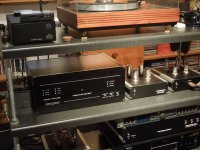
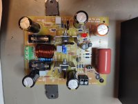
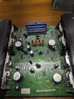
Here’s a photo of a built up amp board in operation:

With larger MKP caps only:

I initially struggled with an oscillation but chased it down to a feedback compensation cap that was too large. That’s all fixed now rock solid. A stability analysis on LtSpice pointed me in the right direction. So the schematic shows a 470pF cap needing to be replaced with 47pF. It’s an easy swap and I’ll do this on the SMT pre populated boards that I will be offering in my shop. I will also have bare PCBs for those wanting to assemble it themselves.
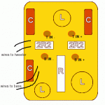
Here is schematic for the overall amp, very simple. Power supply in, audio in, audio out and volume pot with MicroMatch IDC cable to an RK09 pot helper PCB (included).

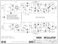
Here is schematic of the Diamond output stage:

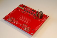
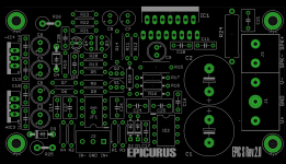
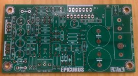
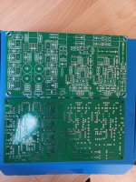
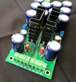
Here is a SMT prepopulated PCB so all you need to do is to install all the through hole parts:

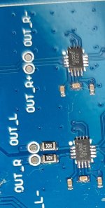
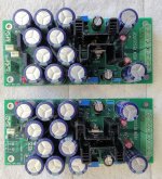
Both sides:

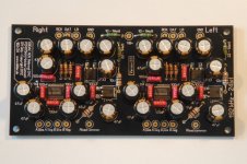
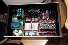
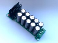
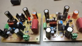
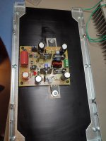
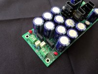
Here is the board assembled with big 4.7uF MKP caps:

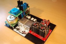
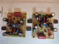
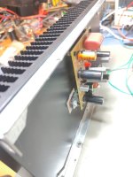
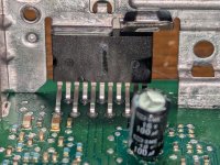
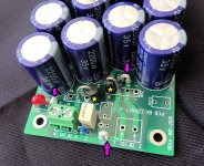
Standard BOM calls for ECB pinout TO-126 BJTs (Toshiba TTA004 and TTC004) but if you have some classic Toshiba 2SA1837 and 2SC4795 (BCE pinout) you can mount them in the bottom like I did here - leaves a cleaner look on top giving you lots of access to the parts:


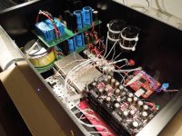
Testing on the bench:


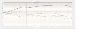
Nice low distortion but second harmonic dominant distortion profile for 1Vrms into 33ohms:

You will find that this headphone amp sounds very natural and clean, but has an incredible power reserve to deliver bass slam while maintaining great control authority of the driver transducer cone. It’s a wonderful headphone amp to listen to for hours. For normal headphone use (under 500mW power) basic AC/DC modules designed for delivering circa 350mA into 15v can be used with a 7812/7913 voltage regulator and it will work fine. You can also make really fancy PSU with linear trafos, cap multipliers, CLC, and low noise LDO’s etc. with a proper PSU capable of 750mA and +/-15v you can drive up to 1.5W into 32 ohms (for those fans of the HiFiMan HE-6).
I’ll be offering the SMT preassembled PCBs for $59. Bare PCBs for $22. Boards are all 1oz copper and ENIG finish.
https://xrkaudio.etsy.com/listing/1659118057
BOM is here. Note that BOM calls for OPA1642 but the pre-populated PCB has NE5532 installed. This was due to availability issues but I can assure you that the NE5532 sounds fantastic and measures well too. If you want to swap it out later, you are welcome to do so.
If you want to boost the output BJT bias current (80mA) for operation to a higher power under Class A, use this 2.2ohm metal thin film emitter resistor (R213/213/312/313):
https://www.mouser.com/ProductDetail/Vishay-Dale/TNPW12062R20DEEA?qs=vHuUswq2%2BswIE18TmZVkaQ==
Note that the heatsinks will get significantly hotter and the PSU also needs to provide more quiescent power.
For the 8pin Wurth IDC cable with matching connector for the potentiometer, get this cable (or its equivalent).
This desktop variant uses TO-126 output BJTs with dedicated heatsinks and does not have the separate MOSFET rail switching needed for the pocket one. The setpoints have been optimized for a moderate 40mA nominal bias current that will let you run in full Class A operation for most headphone uses. It will leave Class A around 250mW into 32 ohms. Of course, you can adjust the emitter resistors to run higher bias currents. I have used it with +/-9v, +/-12v, +/-15v and +/-18v supplies and they all work great. It was designed for 15v rails but I don’t think performance suffers much from using lower voltage. For your particular use case you may want more voltage. High impedance 300ohm cans like more voltage, for example. There is lots of room for input cap rolling and I have used huge 4.7uF 400v MKPs and also smaller 0.47uF film to bypass 10uF Elna Silmic electrolytic caps.
Here’s a photo of a built up amp board in operation:
With larger MKP caps only:
I initially struggled with an oscillation but chased it down to a feedback compensation cap that was too large. That’s all fixed now rock solid. A stability analysis on LtSpice pointed me in the right direction. So the schematic shows a 470pF cap needing to be replaced with 47pF. It’s an easy swap and I’ll do this on the SMT pre populated boards that I will be offering in my shop. I will also have bare PCBs for those wanting to assemble it themselves.
Here is schematic for the overall amp, very simple. Power supply in, audio in, audio out and volume pot with MicroMatch IDC cable to an RK09 pot helper PCB (included).
Here is schematic of the Diamond output stage:
Here is a SMT prepopulated PCB so all you need to do is to install all the through hole parts:
Both sides:
Here is the board assembled with big 4.7uF MKP caps:
Standard BOM calls for ECB pinout TO-126 BJTs (Toshiba TTA004 and TTC004) but if you have some classic Toshiba 2SA1837 and 2SC4795 (BCE pinout) you can mount them in the bottom like I did here - leaves a cleaner look on top giving you lots of access to the parts:
Testing on the bench:
Nice low distortion but second harmonic dominant distortion profile for 1Vrms into 33ohms:
You will find that this headphone amp sounds very natural and clean, but has an incredible power reserve to deliver bass slam while maintaining great control authority of the driver transducer cone. It’s a wonderful headphone amp to listen to for hours. For normal headphone use (under 500mW power) basic AC/DC modules designed for delivering circa 350mA into 15v can be used with a 7812/7913 voltage regulator and it will work fine. You can also make really fancy PSU with linear trafos, cap multipliers, CLC, and low noise LDO’s etc. with a proper PSU capable of 750mA and +/-15v you can drive up to 1.5W into 32 ohms (for those fans of the HiFiMan HE-6).
I’ll be offering the SMT preassembled PCBs for $59. Bare PCBs for $22. Boards are all 1oz copper and ENIG finish.
https://xrkaudio.etsy.com/listing/1659118057
BOM is here. Note that BOM calls for OPA1642 but the pre-populated PCB has NE5532 installed. This was due to availability issues but I can assure you that the NE5532 sounds fantastic and measures well too. If you want to swap it out later, you are welcome to do so.
|
If you want to boost the output BJT bias current (80mA) for operation to a higher power under Class A, use this 2.2ohm metal thin film emitter resistor (R213/213/312/313):
https://www.mouser.com/ProductDetail/Vishay-Dale/TNPW12062R20DEEA?qs=vHuUswq2%2BswIE18TmZVkaQ==
Note that the heatsinks will get significantly hotter and the PSU also needs to provide more quiescent power.
For the 8pin Wurth IDC cable with matching connector for the potentiometer, get this cable (or its equivalent).