Amplifier Feet

Anyone have recommendations for a decent set of feet for heavy amplifiers? I have some vintage SS amps from the 1970s that are heavy and the feet have deteriorated. I would like to find decent feet and I am not finding anything I really like. I checked Amazon, Parts Express and Mouser. I don't really want those black stiff rubber feet that are 5/8 in diameter and similar height.

The feet that are on the amps now are an inch wide and probably some sort of rubber...which has now cracked and become brittle. Any info or links to examples would be appreciated.

Thanks

Hornresp diaphragm excursion

I'm modelling front-loaded stubbed horn with throat chamber and rear vent. I'm using 2x 18DS115-8 in the model.
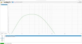
Currently I have a 20 mm peak @ Eg=116.62V which is 3.4kW @ 4ohms. Driver's Xmax is 16.5mm.
How realistic is the calculated displacement considering the model uses pure sine wave for the calculation?
What diaphragm displacement should I accept in the model?

Attachments

  • Screenshot 2024-12-23 141126.png
    Screenshot 2024-12-23 141126.png
    12.7 KB · Views: 50
  • Screenshot 2024-12-23 141151.png
    Screenshot 2024-12-23 141151.png
    11.5 KB · Views: 47

Class A/B vs chip amp

So I have a class A/B car amplifier that I've measured with an oscilloscope to do 100 watts rms per channel with a 1khz sine wave. I also have a tda7498e chip amp that I've measured to do around 107-115 watts rms both on 4 ohm. The car amp power rails are 40v each and I'm currently running the tda7498e off 8 lipos that start at 33.5v yet the chip amp gets much louder than my class A/B with 80vpp. What gives? The class d sounds much better to me as well. I think it's time to start investigating boost converters. If I can find a converter that works I think I'll run 2 of these btl tda7498es
  • Like
Reactions: arthur

Grumpy old recluse here.

As I've slowly turned into a grumpy old dude simplifying my life has become a much bigger priority. So I've gone from being an audiophile to some KRK studio monitors as my main speakers. I'm also a person with a lot of expensive hobbies (I just spent $1,400 on a sim racing setup) and as you know you can't have the best of everything in all of them. Anyway, happy to be here and do some lurking.

Pointing lasers at stuff

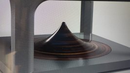
whilst fooling around while bored, I pointed a cat laser at a vinyl disk, and when I held up a piece of paper to the reflection, I could kinda see the individual grooves, but no detail. I then continued experimenting, where the farther away I saw the reflection the more pronounced the grooves got.

However I could not see the individual bumps inside the groove, so I got an idea, if I could take three lasers, two of them are focused on the angled sides of an individual groove, and one that points directly at the groove and reflects off of it to track it, with all these reflections pointed at photodiodes.

I know this has already been done, but, if I could, what would that entail? This is purely hypothetical, I know it’s not exactly simple. I have an excess of CD and DVD players about, all with lasers I could steal, but would a CD or DVD laser make it so I could actually see the grooves? The cat laser does not let me see what’s in the grooves, only the grooves themselves. Do I just need to focus the cat laser better? Or is this way out of the scope of things I can haphazardly hack together.

Questions on old multiway speakers and G'day from South Australia

Just assembled my first 'hifi' rig on the weekend.

(furniture solution pending)
1734396880664.png

Full disclosure - I'm not a hifi person, I don't know anything.

All I do know is about guitar amplifiers, speakers, pedals, FX, etc.

The reason I'm here is because I finally got around to procuring some hifi speakers to test/accompany this stereo tube amp I built last year.
1734397014575.png


here's one of the speakers
1734397070422.png

found on gumtree for (what i consider to be) a good deal.
i am told (& as per listing) they were built in the 1970s (by the seller’s DIY/enthusiast brother)

- cabinet dimensions:
75cm / 29.5” tall
48cm / 18.9” wide
30cm / 11.8” deep
constructed with 3/4” particle board.

- 12” drivers are Philips AD12100/W8
(yet to actually confirm, but it looks like they might be?)
the dust caps have ‘perished’ 😟
- apparently the other drivers are also philips/netherlands origin.
(looks like midrange drivers might be AD0210/AD0211, tweeters could be AD0160?)

  • vinyl player is a cheap entry level (AUD$90 in 2012 i think)
  • ultra budget phono preamp ($20?) - runs on 12V DC supply (opened it up the other day, it’s thru-hole, looks like it might be running either NE5532 or TL072, cant really see, there’s a steel shield heavily soldered over the top of part of the PCB)

Maybe my ears just aren’t golden enough, but to me this setup sounds shockingly good - especially considering the bandwidth-limiting guitar OTs etc.
also,
  • supposedly the crossovers have never been recapped (wish me luck with opening the back panels)
  • i’m an idiot and tested them with totally mismatched 12AX7s so the 2 channels had slightly different tone and gain (making it more difficult to level match) but it didn’t matter, still sounded great.

so how much does it matter about the missing dust caps on the 12” drivers?
- is it worth attempting to repair/replace them myself? (implied dustcap footprint diameter appears to be 70-72mm)

also one of the midrange drivers is a little bit squished/dented
- should i just leave it? or can this be remedied?

[I acknowledge there's queries in here that may be better posted in a specific thread/sub-forum, but I can't do that right now]
  • Like
Reactions: jawen and EarlK

looking for info on your lazy susan

I am building a 17.5 inch lazy susan for my workbench to rotate receivers and amps more easily.

I have the wood round and have stained it.

I want to hear from others that use a lazy susan about my final setup (after attaching the susan base)

have you put a protective coating on yours ?

I am thinking of possibly getting a carpet tile to put on the susan

if you thought a coating was best, what did you use and how has it endured the placing of heavy equipment

thanks

Transistor gain selection

Hi guru's,

I'm at a position where I can obtain some new and original Sanken output transistors, TO-3P.
I'm wanting them for replacing original TO-3 metal transistors in some of my Sansui amplifiers if needed.
I have successfully used 2SA1693/2SC4466 in a rebuild, they are 20mhz parts, without instability issues.

I wanted the the lowest gain parts, "O"= 50-100 hFE, to be closer to the originals but they only have high gain "Y" = 90-140 hFE.

( O= 50-100, P= 70-140, Y = 90-140)

I'm not educated well enough to fully understand the relationship of the gain when switching out these parts however I still would like to get the parts if higher gain would work as the lower would.

Tia.

Ben

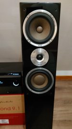
HECO Celan XT 501

Hi.
I have bought a pair of them.
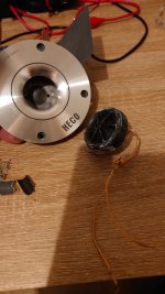
But someone burnt tweets and put inside front plate car doom tweeter.
Speakers are 180w/300w 4-8ohm 2.5 way.
Drivers mid and bass 8ohm (5.4ohm DC)
Tweets unknown, I think they were 8 ohm as well but previous owner doesn't leave old parts unfortunately.
I contacted HECO directly and tweets are eol (end of life) I was ask them about tweeter specification but they refuse to answer.
I Google a lot and get just tiny amount of information. 1st crossover point it's 300hz 2nd 3400hz.
I bought SB acoustic tweeter 4ohm crossover point 2500hz and monacor 8ohm with similar crossover point. SB Acoustic handle 120w, monacor 100w peak (50W rms).
An now my question is. Can I use any of those tweeters?
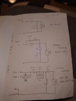
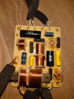
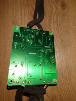
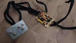
I have attached picture of crossover schematic, I haven't measured inductors and resistors. But I will do if it's necessary.

Attachments

  • 17348972811604409838422707578807.jpg
    17348972811604409838422707578807.jpg
    204.5 KB · Views: 62
  • 20241218_204430.JPG
    20241218_204430.JPG
    579.5 KB · Views: 57
  • 20241218_204412.JPG
    20241218_204412.JPG
    573.3 KB · Views: 53
  • IMG-20241219-WA0023.jpg
    IMG-20241219-WA0023.jpg
    124.9 KB · Views: 50
  • IMG-20241210-WA0002.jpg
    IMG-20241210-WA0002.jpg
    234.1 KB · Views: 52
  • IMG-20241218-WA0005.jpg
    IMG-20241218-WA0005.jpg
    215.1 KB · Views: 59
  • SB26STCN-C000-4.pdf
    SB26STCN-C000-4.pdf
    952.8 KB · Views: 34

Preamp for Hiraga Le Monstr 2024

Earlier in October and November, we posted some details of a preamp for our own Le Monstre 2024 :
www.diyaudio.com/community/threads/hiraga-le-monstre-2024.413301/post-7834924
www.diyaudio.com/community/threads/hiraga-le-monstre-2024.413301/post-7850825

Finally, Fran found some time to finish both the power amp and the preamp for listening.
www.diyaudio.com/community/threads/hiraga-le-monstre-2024.413301/post-7879347

We have now everything proven, and can publish in time before 2024 comes to an end.
For 2025, we still have some refinements for the ladder attenuator planned, as well as building and measuring with other transistor combinations.

In the meantime, happy reading.


Merry Christmas and Happy New Year,
Patrick

.

Attachments

L Shape port and WBIN??

Hello,
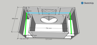
I’ve encountered a problem while determing the ports for my cabinet. I’m not sure where exactly I should measure from and how to do it correctly. Does port represent only blue part or with green? Or only green, and blue part as a front chamber?
So far, I’ve been using ChatGPT to calculate and tune the ports for me, but I’ll admit, I’d really appreciate some feedback and opinions from professionals.

I’m attaching a file with my design for reference.

Attachments

  • Sub 18 v2.2-3.png
    Sub 18 v2.2-3.png
    322.5 KB · Views: 80

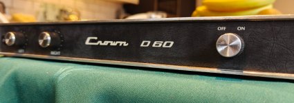
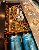
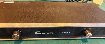
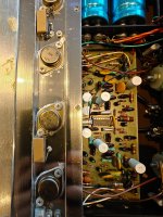
1974 Original Crown D60

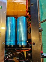
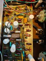
Here I have a Crown D60. Dated 1974.

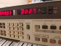
This has all original components including the electrolytic capacitors. Considering it's age it has impressive performance. DC offset is 0.001mV on both channels. THD measures 0.0027-0.0032% on both channels at 1Khz into a 8ohm load. Transformer is hum free and even the neon lamp still works. 47 watts into 8 ohm load at clipping.

I've always admired this topology from the designer Gerald Stanley of Crown. Patented class AB+B outputs run in a Class B. EF3 output stage. Quasi Comp output. Outputs only carry lower impedance, higher wattage loads. Only a very small amount of bias is running in the output transistors.

Very well made and easy to service.
I have many Crown amplifiers in my collection.

Attachments

  • IMG20241221120257.jpg
    IMG20241221120257.jpg
    281.5 KB · Views: 104
  • IMG20241221115438.jpg
    IMG20241221115438.jpg
    473.7 KB · Views: 98
  • IMG20241221120207.jpg
    IMG20241221120207.jpg
    446.9 KB · Views: 102
  • IMG20241221115303.jpg
    IMG20241221115303.jpg
    604.4 KB · Views: 101
  • IMG20241221115010.jpg
    IMG20241221115010.jpg
    675.7 KB · Views: 106
  • IMG20241221115005.jpg
    IMG20241221115005.jpg
    667.9 KB · Views: 101
  • IMG20241221115001.jpg
    IMG20241221115001.jpg
    503.8 KB · Views: 92
  • IMG20241221193736.jpg
    IMG20241221193736.jpg
    246.9 KB · Views: 91

Building a sub with Kenwood KFC-W2510

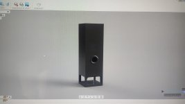
i plan to build a sub for my saloon set up. Already have a pair of three way towers with 10" woofers that goes around 40Hz deep, . I have a mint condition KENWOOD KFC-W2510 laying around, crossover and more than enough amp. I've been countless hours playing with WINISD, and researching, but i cannot decide the basics of the build. My goal is to get some extra low end from 40 Hz down. HOW LOW DO YOU THINK I CAN GO WITH THIS DRIVER? any suggestion for the tunning frequency? by the way... the kenwood in WINISD database is the W2509, but all parameters are the same... im thinking a 50l box tuned at 24Hz? after build i will apply a likwitz LPF AT 50... but all this can change, please tell me if all this sounds good or i have any big mistake . Something like this:

Attachments

  • Imagen de WhatsApp 2024-12-20 a las 09.32.30_621b0c0f.jpg
    Imagen de WhatsApp 2024-12-20 a las 09.32.30_621b0c0f.jpg
    82.7 KB · Views: 36
  • Imagen de WhatsApp 2024-12-20 a las 11.25.02_c38c361d.jpg
    Imagen de WhatsApp 2024-12-20 a las 11.25.02_c38c361d.jpg
    393 KB · Views: 33
  • Captura de pantalla 2024-12-23 091010.jpg
    Captura de pantalla 2024-12-23 091010.jpg
    172.8 KB · Views: 31

KEF Q150 breeding

I have been thinking about diying something based on KEF coaxials for a long time... Now I noticed this discount offer and orderd two pairs.

https://www.auditorium.de/en/speakers/speakers/compact-speakers/kef-q150-bookshelf-speaker

Q150 is the cheapest coax that KEF makes, and the driver mostly lacks bass performance and power capacity. Xo circuit must be very simple. It was tested with Klippel NFS by Erin

https://www.erinsaudiocorner.com/loudspeakers/kef_q150/

Response is pretty good! Obviously there is great potential for dsp-xo and 3-way system!

1692805010207.png


Göran ("gornir" at diyaudio) has measured the R series coaxial http://www.audioexcite.com/?page_id=3614

Here Q100 with same 5,25" tested by Amir https://www.audiosciencereview.com/forum/index.php?threads/kef-q100-speaker-review.11987/
and Q350 with 6,5" https://www.audiosciencereview.com/forum/index.php?threads/kef-q350-speaker-review.13484/

SE amps and speaker cone motion

Hi everyone.
I have been fooling around with a pair of ACAs and I'm not sure if I understand what is going on as I change their mode of operation.
As i understand it, in the standard mode it is a single ended amp with one output terminal at ground potential and the signal applied to the other speaker terminal. This signal varies from zero volts to some positive value but never goes negative. Since the amplifier inverts the signal, the positive speaker terminal is the one that is grounded and the negative terminal gets the signal.
Parallel mono is the same situation with both channels acting the same way while bridged mono inverts the signal to the other channel and floats the signal with no ground reference.
So far so good, but...
Doesn't this mean that in standard mode the speaker cone is always on one side of "zero"? With no signal the cone is at rest in the center of its travel range. Once a positive signal is applied to the negative terminal the cone will move backwards into its suspension. When will the cone ever move past the at rest position?
In balanced mode I think that the cone will vibrate about the zero, 'at rest' position. In SE mode, isn't all of the vibration on one side of zero? Would this apply to SE amps in general, including transformer coupled tube amps?
On my LaScalas the ACA amps sound MUCH better in balanced mode than parallel mode and I don't think that it's the extra voltage swing that is the difference.

Help! I want to understand and I'm not sure that I do.

Pete

QJ HIFI audio Store on aliexpress.com - The Aluminum Amplifier Enclosures That Never Arrived

Just a tale of woe for others to be aware of so that they don't fall into the same trap that I did.

I ordered some amplifier enclosures from QJ HIFI audio Store on aliexpress.com during the black Friday sales. They were listed with free delivery. Please see the picture below.

I ordered 1 to begin with to see if they would ship it. Then it was marked as shipped and a tracking number was provided so I assumed everything was OK. I waited until it got to my country before ordering a second one since the price was very good.

Instead of receiving the enclosures, I received absolutely nothing. In due course, the parcels were marked as delivered to somebody else in different cities. After discussions with NZ Post, they revealed that the contents of the packages were something else entirely. Not amplifier enclosures at all.

So this seller provided me with tracking information to somebody else's parcel that was also being shipped to my country. Since this happened twice with two different parcels, it was not simply a mistake made by the seller. It was intentional dishonesty.

The seller sent me a message saying that the item was shipped and everything was progressing normally. Later I received another message demanding 110 USD of additional shipping fees. I wouldn't spend another dime there, let alone provide them with another 110 USD!

I marked the items as not received and got a refund through aliexpress. But the entire experience has put me off buying anything on this site. From now on, if I do buy anything there, it'll just be stupid items like a few screws or some clamps for wires etc. Nothing substantial.

Attachments

  • Screenshot from 2024-12-16 18-05-40.png
    Screenshot from 2024-12-16 18-05-40.png
    133.9 KB · Views: 119

Heaving bed

We have decided on a daybed instead of regular sofa for movie watching as we all like to cuddle up

I am working on the design now and stuck on n the working surface for the bass exciters. What is optimal? A regular slat system or slats on suspended rails? I can place 20x20mm rubber on the rails before putting the slats down. As well on slat ends

I can also mount squares of ply under the slats for the exciters. Never done anything like this so some guidance on bass exciters would be very appreciated

Ample class d power available with many types of modules on hand

Thanks and regards
Randy

Bass Shelter, subwoofers and two cats

Hello all. Trying to reorganise a massive project, bringing together a number of personal and semi pro projects together as the various subprojects are either interdependent or closely associated. I do most of these in step, working on a bit at a time

I have 5 years to complete the larger host projects and a fully equipped workshop and parts bin

Warning
The first 8 pages are full of very heavy going non-linear textual musings, revisions and misunderstandings. Best skip to post 156 as this is where systems are worked out and the real development work begins. I have found it impossible to convert the way my mind connects things to linear text, so the work part will mostly be pictorial with an open invitation for any aspect to be raised into a discussion

Breakdown of the subprojects

Tiny40s Subwoofer Challenge
Try to make a tiny subwoofer cab that can work down to 40hz or better with solid bass for close quarters listening. Been messing with this a bit and trying out a few things before making a full project of it

Volcanoe Bassinga Subwoofer
For my soundsystem. Trying to shrink deep low bass to small, highly transportable and adorable set of 4 cabs. Using pro-moble drivers

Volcanoe Bassinga, Marine Subwoofer
For my marine soundsytem, based on Polk Audio marine certified drivers

Volcanoe Nearfield Bass Monitor
For video and audio editing

Volcanoe Bassinga PR
Custom DIY marine grade passive radiators

Wavesinga Marine Subwoofer Driver
Custom DIY marine grade high xmax rotary motor driver

Club Sandwich
Porting boatbuilding FRP composites tech to subwoofer cab construction demo. Using digital workshop tech to eliminate messy bits. This will be used for cabs for the Volcanoes

These subprojects will be hosted on these project crafts

Bass Shelter
Mobile DJ booth. Promoting sound system hire, bass amp and guitar sales as well as new and used music shop and karaoke spot. Road transportable by trailer or carried on a 6m pontoon boat. This needs to have a self-sustaining electrical power systems for occupied use and an aux generator for letting rip. Following the local markets and events calendar

Volcano Soundsystem
Reggae, Dancehall and Reggaeton DJ plus karaoke and sound system hire. The focus here is massive bass systems and developing massive bass performance out of very small cabs. This will also feature a marine grade soundsytem and a set of marine grade 2.1 near to midfield systems

Bop
A 6m pontoon boat based on a pair of custom HDPE hulls with very narrow beams for good performance at displacement speeds. This vessel will be used as a floating music related for hire venue and family use. Built to marine survey

Tender to Bop
A Smartwave 3500 with a 30hp outboard. This vessel will dock with Bop as a central nacelle and petrol motive power. Basically a ute and lifeboat daughter craft. Built to marine survey

Bassinga
Daily use beachcat and on the water home office/nursery! An electric/human/wave powered craft that most of the subprojects will be fitted to

Bass Phoenix
A soundsystem masquerading as a beach exercise and transport machine 🙂 Built to Australian standards and marine survey. This chassis will be the basis of an etrike and water toy

I am in Hervey Bay, Qld. This is a sparsely populated area with large areas of calm water and long and empty beaches. It is also a major tourist hotspot and beach hire, markets, festivals and food truck type culture is alive and encouraged here. Noise pollution is not an issue as I will feature polite volume from the booth or tender, while nearby there is a loud Zumba joint that gets pretty loud. Some permits and are in place and some will be acquired once there are enough relevant details as the project matures

All comments and thoughts are welcome, as this more than experimental or downtime stuff. Anything that can pick out potential problems and pick apart misconceptions and fails would be amazing. I am well versed on the construction and marine side but acoustic design and electronics, I struggle

Bass shelter playlist
https://youtube.com/playlist?list=PLvXGZdJdbP2Lb-gYFxsxefvdCw0hHY3k7&si=FVas4cf5Nolw9BPg
  • Like
Reactions: head_unit

what is the point of expensive coaxials with ragged response?

Stuff like
https://www.madisoundspeakerstore.com/coaxial/seas-excel-c18en002/a-e0060-6.5-coaxial-each/
https://www.madisoundspeakerstore.com/coaxial/seas-excel-5-magnesium-cone-coax-c16n001/f-e0051/
https://www.madisoundspeakerstore.com/coaxial/satori-mt19cp-8-coaxial-with-papyrus-cone-8-ohm/
etc etc etc
OK many woofers in this life are not so smooth on top.These tweeters though are ragged, some with huge response holes, and dying above 10k or even less. I'm sure folks are using these and saying they sound lovely blah blah...but who would ever buy loose tweeters measuring like this?!?
What am I missing?

Seeking rectifier suggestions for Aragon 4004

I'm looking to resuscitate my old Aragon 4004MkII, which had developed a substantial hum some years back. The existing rectifiers are KBPC3504DW units, and while the diodes still look superficially functional, the reverse current is wildly out of spec on several of them (according to my $15 ebay part checker), and when hooking them up to my bench supply and testing with higher voltage, they reverse conduct >100ma at less than 5 volts.

Sourcing replacements is easy enough (though I'm not sure what the "D" in the part number stood for,) but I'm thinking perhaps something better might be available, considering the years elapsed. I've read a few discussions on the topic, but it's far enough out of my expertise that I can't really assess who knows what they're talking about.

So any suggestions for something that's not too much more expensive than the replacement rectifiers (less than double the $4.20 each for original)? Or perhaps there's some established design for a similarly powerful amp that I could crib off of. I have no issues with soldering together discrete diodes to build them up.

For reference, the supply is +/- 70V, 18000uf capacitors, and the transformer windings measure .5 ohm. I'm not sure how to calculate the startup surge, but I'd have to guess 'substantial."

Intermodulation Distortion midbass shootout Purifi Anarchy plus maybe more

The following is a comparison of Intermodulation distortion (IMD) in 6-7" midbass drivers.

One of my lockdown speaker projects was to measure harmonic distortion and IMD in 14 10-12" subwoofers. See the thread here: A tale of 12" subwoofers, distortion and 15 dollars.

What I learned from this exercise is that the drivers that sounded subjectively more clear had lower IMD levels.

I thought I would continue the fun and measure a few 6-7" midbass drivers. I'm sure most people on this forum know, but IMD is similar to harmonic distortion except more than one tone is used. For my test I used tones at 40and 96hz as well as 50 and 210hz. Many years ago Paul Klipsch wrote a paper on how IMD is linked to cone excursion so I wanted to test the drivers in a situation where cone excursion is high and the IMD products are above the noise floor.

The test enclosure is a .5 cu ft (14 liter) sealed box with the bottom lip of the speaker just 2 inches above the floor. The microphone is on a stand 49"high with the base of the microphone 33" from the driver. A distance of about 1.5m from the speaker to the microphone. As I'm not measuring in an anechoic chamber my measurements are not comparable to anyone else's but comparisons can be made between the drivers I test.

The first two drivers I was able to test are the DIYSG Anarchy and the Purifi PTT6.5X04-NFA-01. As shown in the graphs the Purifi really shines in this IMD test. Yes, the anarchy is less than 1/5 the price and it does well for the money but the Anarchy seems to be affected by a lack of inductance control.
Erin's audio corner has klippel tested the purifi (XBl at 82%, Bl = 9.1mm, and for XC at 75%, Cms minimum was 6.9mm and the anarchy was klippel tested for the voice coil magazine (XBl at 82%, Bl = 8.5mm, and for XC at 75%, Cms minimum was 10mm). So a pretty close klippel result but the purifi outperforms the anarchy in all IMD and harmonic distortion tests I conducted.

For the 40 and 96hz test look for IMD products at 56,136,152,176,232
For the 50 and 210 test look for IMD products at
60,110,160,260,310,370

I will later convert the graphs into IMD percentage.
I am open to comments and recommendations of drivers that might do well in this test.

Attachments

  • Combined40IMD70db.jpg
    Combined40IMD70db.jpg
    242.7 KB · Views: 1,269
  • Combined40IMD80db.jpg
    Combined40IMD80db.jpg
    243.7 KB · Views: 1,213
  • Combined40IMD85db.jpg
    Combined40IMD85db.jpg
    241.3 KB · Views: 1,163
  • Combined50IMD70db.jpg
    Combined50IMD70db.jpg
    248.3 KB · Views: 1,126
  • Combined50IMD80db.jpg
    Combined50IMD80db.jpg
    229.2 KB · Views: 1,118
  • Combined50IMD90db.jpg
    Combined50IMD90db.jpg
    249.9 KB · Views: 658
  • IMG_2980[1].jpg
    IMG_2980[1].jpg
    880 KB · Views: 872

Introduction

Hello, fellow forum members. Greetings from Brazil!

I'm new here, as you might've already guessed. Thanks for having me in this select audio forum, and I hope I can contribute to this fantastic knowledge base in the future.

Brief Background
I've been an electronics aficionado since I was a child and, more recently, I'm expanding my area of interest towards electroacoustics and embedded systems.

Currently graduating in mechatronics engineering, my most recent working experience was as a full-stack developer, writing and debugging code in C#, Ruby and Elixir.

Cheers!

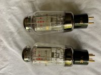
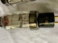
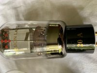
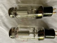
FS Pair of EML 20A mesh

I am selling a pair of EML 20A mesh that I'be bought in January and barely used it ( about 200 hours ). They are broken in as recommended by Emission Labs and work perfectly.
Asking $550 plus shipping from 06851.

Attachments

  • IMG_5835.jpg
    IMG_5835.jpg
    698.4 KB · Views: 593
  • IMG_5836.jpg
    IMG_5836.jpg
    523.1 KB · Views: 573
  • IMG_5837.jpg
    IMG_5837.jpg
    446.2 KB · Views: 545
  • IMG_5838.jpg
    IMG_5838.jpg
    630 KB · Views: 534
  • IMG_5839.jpg
    IMG_5839.jpg
    780.7 KB · Views: 503
  • IMG_5842.jpg
    IMG_5842.jpg
    630.3 KB · Views: 170
  • IMG_5840.jpg
    IMG_5840.jpg
    848.4 KB · Views: 192
  • IMG_5841.jpg
    IMG_5841.jpg
    830.3 KB · Views: 161

Your favorite 4-5” midrange driver?

Looking for folks experiences with 4-5” drivers used as dedicated midrange/midwoofers…..doesn’t matter if it’s a commercial speaker system or DIY effort. Purely subjective of course……since it’s covering the most important part of the frequency spectrum, to me…..that’s all that matters.

I‘ve been eyeballing this guy for use as a mid

https://www.parts-express.com/pedocs/specs/292-662--visaton-b100-spec-sheet.pdf

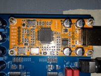
Xmos XU208 Daughter Card Software Issue

Helllo to all,

I had started a thread, about the Chinese DAC Board, but not much replay.

Now, I need information's about the Xmos XU208 Daughter Board.

This board is sold at Ali Express, Amazon, Ebay and more.

I cannot install this Xmos board to my computer.

I think, that board have no Firmware loaded, it is empty.

Does any one have some experience with this Xmos XU 208 board?

Any information's about Firmware and Software for this board.

I hope, somebody have some experience with this Board.

Thank you.

Attachments

  • 20191208_092041 copy 30.jpg
    20191208_092041 copy 30.jpg
    375.4 KB · Views: 267

Interchangeable drivers in popular full range speaker plans

When reading about transmission line or back horn type designs the literature says they're very complex designs but then I read on forums people using designs like the frugal horn and people swapping and changing different drivers into the cabinets which to me seems like they're not so finely tuned to a driver and complex as I thought. What am I missing?

Troubleshooting Monster Power HTS-3500 MKII conditioner

Hi everyone, new here.

This Monster HTS-3500 MKII has an analog voltmeter dial that does not register any voltage and is not lit while the unit is powered.

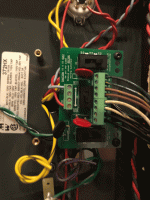
The PCB at the back of the voltmeter gets 120 Vac from the main board. Traces upstream on that 120Vac path on the main board burned up. Someone bridged them and they burned up again in a different spot. The voltmeter PCB itself showed no signs of overheating and components tested OK, so I bridged the burned traces in that 2nd spot and powered up the unit with the voltmeter PCB installed, but not the meter itself. Everything looked OK - no overheating, suggesting the meter itself is the culprit somehow.

voltmeter pcb2.jpg


The meter has 4 terminals: posts A and B, and leads C and D. Posts A and B connect to the movement (?), 75 ohms across them. Leads C and D are connected to two pins at the bottom of the dial face. Infinity ohms across them.

img22.jpg


dial2.jpg


My questions:
  • First and foremost, could anyone point me to schematics for this unit? I searched high and low but came up with nothing.
  • On the voltmeter PCB, there is 13.7Vdc across A and B when the unit is powered. However, just 1.5V from a AA battery across A and B on the meter is enough to bury the needle. I don't want to connect this meter until I understand why the circuit is sending 13.7V into an instrument that's overdriven at 1.5V?
  • Are C and D just holder pins for a lamp that has been removed?
  • If so, what is the black cube-shaped component just upstream of C and D on the control board? Googling WT-EL7 did not yield any results.

Elsewhere, this unit has six always-on receptacles that are powered, and four switched receptacles that are not. That issue looks unrelated to the voltmeter though, so that's one for another day 🙂

Any thoughts and ideas would be much appreciated! Thanks in advance everyone.

How to Soft Start Power Supply that has been sitting for Years

Hi,

Like the title says I need to power up an early 90's amplifier power supply that has been sitting for many years. At least 5 and probably closer to 10 since it has seen line voltage. Just the bare power supply, the transistor board has been removed.

It is basically a big Toroidal transformer with rectifier and (4) large 10,000 uf / 90 volt capacitors. Output is +/- 80 volts.

I have a Variac transformer on order. Do I just start from say <10 volts AC and bump the voltage up once every hour until I reach house power of 120 volts over a period of many hours?

Thanks for your help!

Understanding Bessel array radiation patterns?

So using the 5x derivative as it’s the only one Keele thinks has a practical purpose……the two outermost drivers are the main energy drivers of the system with each unit representing one 1/4 wave spacing…….would that suggest that the overall dispersion pattern would be equal to that of the diameter of the same size cone?……let’s say the 5 combined distance is 8”…….are we now talking about the same dispersion characteristics of an 8” cone or point source?………

Home theater build amp over powered

Hello everyone
Home theater systems became very expensive in our country so I decided to build my own home theater. As I am a newbie to this I watched some videos on u tube. I ordered zk-tb21 amplifier from china. It states that it has 200 watts output power 2x50 watts speaker and 100 subwoofer. I am running it on 20volts 6 amp adapter.
Than I ordered 2 two way 6.5inch speakers having 100watts rms and 250 watts peak power each. Impedance 4 ohm each.
Also a subwoofer/woofer 10 inch 350 rms 1000 peak 4 ohm impedance.
Now the prob:
When I go above 50%volume speakers and sub starts to blast. At this level they produce a beautiful sound for small 10x10 room but above this level its like amp is over driving them. Then I connected both speakers in series and ran them on one channel and they were fine. So I added two 80 watts tweeters with each in series and small 4 inch sub with sub. Making all channels run on 8ohm impedance. Now the prob is there is more sound of tweeters then speakers and sub is still being over driven.
How can I optimize this system without adding more cost to produce a good quality sound (enough for 20x20 room)?
How can I stop speakers/sub from being overdriven or blow out? (In case any kid turns the volume knob to full)
How is a 200watt amp over driving speakers almost 4 times its power?

Hello from Illinois: I'm Restoring distortion in an Rock Amp

A christian outfit called Rock Amps out of Pomona CA apparently made a number of SS amps. Mine is from 1978 and unlabeled except for a sharpie SN inside the case and a Stonebridge Music Store Logo from Garden Grove CA. Haven't found a schematic online so I'm working on that. It uses two UA1458TC's, has treble, bass, reverb(spring tank), and a distortion knob. The distortion does very little but the circuit looks like a fuzz, maybe? The large cap on the trace side had come loose and the 20 Ohm resistor was blown. I'm starting to make a schematic to troubleshoot the lack of any significant change when turning the distortion pot. I figure the large cap coming loose whas what caused the resistor to blow, but like I say I'm just starting on this one, identifying components and following traces to get a schematic. Thanks for any input folks!!

Attachments

  • IMG_6531.jpg
    IMG_6531.jpg
    306.4 KB · Views: 117
  • IMG_6532.jpg
    IMG_6532.jpg
    423.7 KB · Views: 121

800W RMS on 2K amp?

I’ve got 2 400W DD audio 510Ds running on a crown XLS2000. 2 cube box tuned to 37hz with a 6” aero port. I can either run the 2 10s on separate channels at 8ohm each (theyre D4 coils) to give them 375W each, or run them on one bridged 4ohm mono channel for 2100W.


Would it be a good idea to just run a -3dB preamp on my DSP so that I can push roughly 1K max instead? My logic is that the 2 375W at 8ohm is peak power, so they won’t be receiving more than 300W realistically. Then setting ~1K to be my max power means I’ll actually be pushing more like their 400W RMS into them. Thoughts?

LM317 current limiter

I've tried the LM317 as a current limiter, see diagram attached. I tried with a variac setting with approx. 165 VDC and a load getting exactly 100 mA without current limiting.

I used a 20 Ohm resistor and expected the current to be limited to 62.5 mA. However in real life testing the current is not limited at all, still giving 100 mA.
What could possibly go wrong with just a single 3 pin device and one resitor? I checked that the output was taken from the Adj. pin.
I just don't get why it's not working.

Regards, Gerrit

lm317_current_limiter.jpg
  • Like
Reactions: lineup

Infinity Reference 60 speakers

Hi Guys, I picked up a pair of Infinity Reference 60 speakers. The voicecoils on the bass drivers are gone, so redoing the surrounds is not an option. I am trying to find the best solution to replace the bass drivers. The GRS cheapies are an option but the 8 ohm version is just to small, the 4 ohm version is slightly bigger and will fit and will give me an F3 of about 50hz, which is not bad but I then I need to change the x over as they are calculated on the 8ohm version. The other option I was looking at was the sb Acoustics but I would.need to vent the box but a.pair of them should work very well. The infinity enclosure is about 2.70ft3 so close to 75 litres. 8″ SB20PFCR30-8
https://sbacoustics.com/product/8-sb20pfcr30-8-paper/

I also have a Alcone 8 AC He, which should.work well in a 75 litre enclosure. I was thinking of using a 8 inch Dayton passive radiator that has an Xmas of 11mm with the Alcone, but I would.need to adjust the xo. What's your thoughts guys any advice would be much appreciated.https://www.lautsprechershop.de/hifi/alcone_en.htm

Pensils A11/P11

I'm seriously considering building a couple of Pensils using the alpair alpair 11ms.

For the cabinet i would go with the pensils from frugal-phile (pensil a11-p11).

I have never heard any of these designs - their simplicity in both cabinet and drivers attract me.

I listen to everything from Norwegian Black metal, death metal, regular pop and rock, electronic music (Björk Homogenic is a favourite) all the way to jazz and classical. I listen at reasonably low levels - usually i woudld be at a soundevel where i can still talk to another person in the room. I have a cheapish class D icepower amplifier as well as a surround receiver from yamaha and may upgrade (wish to) later. I have owned B&W 604 previously as well as amphion. I have a close friend who used to have B&W 805 matrixes and now owns a couple of expensive focals with a high end densen system. I have listened to B&W a lot 15-20 years ago and they are probably some of my favourites.

So now on to the questions:
  • Currently i have a limited budget so going from 22mm birch ply to 22mm MDF for the cabinets will save me a large amount of money. But how unhappy will i be wit that choice?
  • I would consider redoing the cabs at a later time in birch ply - but to decide on that what could i expect in changes soundwise?
- Going without the bracing will spare me the problems of building the brace - but how unhappy willl i be?
  • Will bracing using thick round stock (maybe 40mm diameter) be an option - say everything from 3-6 pieces placed from baffle to back placed along the veritcal axis and maybe some going from side to side help in any way?
  • If i redo them in birch ply, the brace (as described in pensil 12 pdf), might be an option i would consider. What improvements can i expect from such a change (none, roundstock to proper brace)?

So this is a question of the lowbudget version vs full birch ply version of the cabs.

Any thoughts on anything will help in my decision. If you want clarifications i can try - english is not my first language.

Hello from Europe.

Greetings community!
My name is Dmitry, I'm from Riga, Latvia.
Working in ventilation systems manufacturing. Many years interested with vintage hifi - amps and speakers. During years i had to restore many speakers from cosmetic defects to building them from scratch.
Now i get rid of all vintage stuff and started to build few modern speaker projects. I'd like to met new ppl here to get more experience.
  • Like
Reactions: Rokytheman

Logitech Z-5500 subwoofer + adapter

Greetings! My old 5.1 system is already 16 years old, and for the past ~5 years, I’ve been constantly repairing it at service centers.
Recently, the control panel (control pod?) broke again. And I guess it’s a time to let it go. But one thing I don't want letting go is the awesome Z-5500 subwoofer.

I recently purchased the Edifier MR4, and I’m really missing the bass that my 5.1 system (with a large subwoofer) provided. So, I want to pair my old but beloved subwoofer with my new budget monitors.

Untitled-3.jpg

firefox_euLlyKrVbT [22.12.24-21-24].jpg

Question: If I purchase just this ☝️ adapter and connect my subwoofer directly to the motherboard (C-SUB) using it, will it work? Maybe someone already tested this adapter?
Edifier MR4, unfortunately, has NO subwoofer output.


Thanks!

Amplifier suggestion for old 3w speaker

Hello,
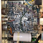
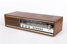
I will be modernizing old Yugoslavian radio called Iskra Savica SN120.
In the process I will remove all electronics and I need a suitable amplifier.
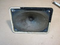
It has oval (10x15cm paper membrane) full range speaker -full range with high sensitivity.

Enclosure is not completly sealed, it has backplate with many holes, like radios did have back in the day.

Those radios (when working correctly) have really nice warm sound that somehow fills the whole house, it also has strong mids.
This is the sound that I would like to keep.

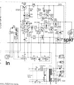
Here is the schematic of original amplifier and I'm thinking of building the same one, except for better power supply:
Screenshot_20240912_083457_Drive.jpg

What do you think of it? Is this class A?
Do you see any room for improvements?

Edit: I had just realised that AC187K and AC188K output transistors are germanium... can I substitite them for something newer? Also should I substitute other transistors with something newer?

I know that this amp goes nice with the speaker, would you recommend different amp anyway?

zvucnik-lampasa-ei-nis-4-oma-3w-osijek-slika-165804471.jpg
This is not the exact speaker, but it's similar enough.

remote.jpg.jpeg


Thank you

2-way omni cube speaker

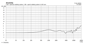
I have been looking for some time for an approach that leads to a loudspeaker with good omni directional properties as well as accurate stereo imaging.
I hope this can be achieved with the this concept:

note: for the simulations I used the possibility in Boxsim to simulate a rectangular enclosure. So, if practice and simulation disagree: blame Boxsim

The argument goes as follows:
If we tilt a conventional speaker 90 degrees backwards we hear at the listening position the signal 6 dB softer and high-frequency filtered.

1725717721115.png


The cutoff frequency in the listening direction depends solely on the cone/dome diameter of the speaker ( Fc Ξ 1/d ). For amplitude, box size, form and driver location don’t matter. For phase however it does, and that’s important.
This low-pass filtering is a sort of “free lunch”.

Woofers and tweeters can be placed on the cube. Below a possible configuration of 2 tweeters and 2 woofers is given with its corresponding spl at the listening position. Besides the cone/dome diameter, the drivers are considered ideal.

1725717832300.png

On top and bottom we have 2½-inch woofers and at front and rear ½-inch tweeters, all placed at the centers of their baffles. The tweeters are high-pass filtered (Fc= 4 kHz, Q=0.7). The woofers are not filtered.
The spl already looks reasonable and can be further improved.

After trying some placements for the drivers for a while I found a placement that gave a quit nice results:

1725717960939.png

1725718038721.png


1725718361034.png


The system distinguish from a conventional 2-way systems by a much better directivity.

In the simulation, this concept produces a loudspeaker with good omni directional properties and a fairly flat spl in the horizontal plane over a reasonable angular range, which should give a wide sweet spot and decent stereo reproduction.
The crux of the concept is that, for every viewing angle, never more than 1 woofer and 1 tweeter are in direct “sight.” This eliminates direct interference between drivers. It seems simple, or am I missing something ?

I want to work out this approach a bit further with a concrete example and hope to post it on this thread soon.

Attachments

  • 1725718117264.png
    1725718117264.png
    40.1 KB · Views: 67

new member

Hey guys. My name is Liv, i built a few aliexpress pcb amps and did a speaker table a few years ago. Im interested personally in all the new stuff and what we can diy, currently building in my head for now an amp with a dsp and checking datasheets for ic's.

Professionally me and a friend are self employed and doing mostly networking projects but somehow a project manager threw our way a pa system and we are stuck. I will make a thread once I am allowed to.

Thank you for approving my account, i've been lurking here for quite some time but its first time I actually want to post 🙂

Modifying Monitor Audio Bronze BX2 Speakers (2010-2015 yr model)

Modifying Monitor Audio Bronze BX2 Speakers (2010-2015yr model).
Part 1 of 7

I completed this project in December 2020, & submitted a shorter version of this write up in July 2021 to the blog of the web shop that I purchased the capacitors, resistors, & inductors from.

Monitor Audio Bronze BX2 Speaker Upgrade | HIFICollective

The following writeup is a “reference page”, more in-depth & contains the parts list.

Disclaimer:-
I do not have any microphones or sound measuring equipment, so no charts/measured tests have been carried out. I am only going by what my hearing tells me. I am qualified in certain aspects of electrical design & have actual hands-on experience on various builds from PCs, Hi-fis, cars, houses, & at one time I worked for the local electricity company!

Intro:-
“To modify or replace”, that is the question I recently asked myself, regarding the Monitor Audio Bronze BX2 (2010-2015yr model) speakers that I purchased new back in 2013. These speakers were highly acclaimed when they came out, & still sounded good. However, being very picky, they suffered from bass boom/resonance via the cabinet, occasional sharp highs & a slightly muddy midrange, with the sound distinctly coming from two speakers & not a wide “soundstage”. This despite toeing them in, moving them away from the walls, bi-wiring them, & trying various other well-known mods & obscure tricks!

I did an extensive amount of research on the web, some info from this forum, some from the blogs on Hi-Fi Collective (especially the one by P.A. Coupe who is Reference Fidelity Components), the huge reference website of humblehomemadehifi.com, & a few others. I was also spurred on after watching videos posted by G.R. Research on YouTube, who analyse numerous main brand speakers with the proper test equipment, then upgrade the crossovers etc. & then retest them. Many times, the expensive speakers have cheap crossover parts, & cheap speakers after modification, can produce better results than the expensive speakers in unmodified format! Many of the modifications I carried out are well known & essential for any decent speaker build/modification. However, some are less well known & others I deviated away from convention!

Some of the design considerations:-
  1. Keep the crossovers the same design, as I wanted to verify that improving the quality of components, without changing values or crossover design/type, would alter the sound for the better, hopefully! Also, I do not have a calibrated stand microphone & suitable measuring software. This being the best way to fine tune crossover component values using actual sound measurements from the drivers.
  2. No more than £20 to be spent on any single capacitor, resistor, or inductor.
  3. Make the internal cables easily removable from the board & back panel connectors, as per the original crossover.
  4. Reduce extraneous metal from the signal path where possible, especially from the binding posts!
  5. Internal cables & inductor wire gauges to be equal to or thicker than the component leads, with the LF inductor being thicker wire gauge than the HF inductor.
  6. Remove other traits from the components, i.e., inductors to have low resistance, resistors to have low inductance, capacitors to have low ESR.
  7. Tighter component value tolerances, i.e., 1% or 3% at most, instead of 5% or 10%.
  8. All electrical contacts to be non-magnetic (to reduce other “influences”), brass or oxygen free copper, & gold plated, if possible.
  9. Solder used to be lead free silver solder (tin/silver/copper by Shenmao).
  10. All fixings to be non-magnetic, & stainless steel, to reduce other “influences”.
  11. Reinforce, deaden & remove resonances from cabinets.
  12. Make the modifications look “factory” or better than “factory”.

Enclosure Damping Alternatives?

I'm curious about recommended alternatives to wool felt damping for a center channel.
Locally, there is a suppier of 1/2" thick F-13 wool felt, but the minimum order is for several yards at $150/yard, so I'm researching alternatives. Here's what I've located, but I'm not sure how the various materials compare and which would satisfy the needs of the enclosure:
Very interested in your input. Thank you!

For Sale Pete Millett 'La Luxuriante' R120 tube amp

Design by Pete Millett, more info can be found here: http://www.pmillett.com/r120_se_amp.html

Lovely sounding tube amp with the hard to find R120 tubes as power tubes, driven by an EF36 pentode (with screen voltage regulated by a VR tube) and a cathode follower
This gets you a nice 4,5W into 8 ohms.

The IDHT R120 has been called the European 2A3, and has been one of the favourites of Jean Hiraga, it has also reached cult status in Japan. So few tubes are left in these parts, especially measuring NOS and being matched, like these pairs.

Parts are all chosen to be as exact to the original design, so Kiwame resistors, Elna Silmic II capacitors, Mills cathode resistors and custom Martin Mug output transformers
Power supply is a 5u4gb rectifier, followed by a common CLC supply and each channel is decoupled by an additional LC, driver stage has an additional RC rail.

The power transformer has a PCB designed by Pete Millett to easily switch line voltage, so 100-110-120-200-220 and 240V are all available!

SOLD

Attachments

  • tempImageLCyx8N.gif
    tempImageLCyx8N.gif
    1.3 MB · Views: 577
  • tempImagepN0Pst.gif
    tempImagepN0Pst.gif
    1.4 MB · Views: 2,086
  • tempImagevSrbDB.gif
    tempImagevSrbDB.gif
    1.7 MB · Views: 1,187
  • Like
Reactions: kb2wyl

Mercury rectifier question

Hi y'all! In working on a 15kw vttc which is essentially a class E. Normally these use a silicon diode on the input but I wanna go full old fashioned and use a mercury rectifier. I have two 1.25a 10kv 872a that I can use. While I fully understand the danger I don't know the most about electrical characteristics. Mostly I wanna know is how well to they handle overloaded RMS current and if I can put two in parallel? I know they don't like high peak but I think for short periods and reduced lifespan I can over current. If I put two in parrales i am concerned just one will fire and drop the voltage to where the other will not

  • Locked
Help me reverse engineer and modify a crossover

This is a 3 way crossover:

The biggest issue is that the two smaller coils dont have a label so i dont know the value.
I have drawn the circuit here:

is there a software or webpage that can put this circuit in, and it will tell me the corresponding frequencies? i will have to put in guess values for L1 and L2. maybe L2=1.5mH and L1 = 0.8mH?

the midrange is a tang band titanium wide bander. right now the tweeter is crossed over very low. i estimate somewhere in low 2k based on listening. i want to push it way way higher so that i am mostly listening to the wide bander and the tweeter kicks in much much higher. i also need to bring the tweeter level down 3 to 5 db. i am assuming that will be done by increasing that resistor value from 3 ohm. i know what an L pad is, but in here i only see one resistor for thre entire network. i could add additional resistors if needed. I have those fancy dayton audio 20Watt 1% resistors in 10ohm, 5.6 ohm and 2.3 ohms.

For the woofer i need to figure out what is the cut off currently. i am planning to use the

Dayton Audio DS175-8 6-1/2" Designer Series Woofer Speaker​


the orignal woofer says on it: BC143G. i thought its some B&C. but i cant find anything about it.

SUB project with a KENWOOD KFC-W2510

Good day gentlemen, i plan to build a sub for my saloon set up. Already have a pair of three way towers with 10" woofers that goes around 40Hz deep, but as you all know every extra Hz down there is wellcome. I have a mint condition KENWOOD KFC-W2510 laying around, crossover and more than enough amp. I've been countless hours playing with WINISD, and researching, but i cannot decide the basics of the build. My goal is to get some extra low end from 40 Hz down. HOW LOW DO YOU THINK I CAN GO WITH THIS DRIVER? any suggestion for the tunning frequency?

For Sale PASSDIY 4U/400 Deluxe chassis + some parts

Hi Guys!
I have a new, unused, unassembled enclosure from Modushop: https://modushop.biz/site/index.php...t&product_id=977&search=pass&description=true
FrontPassDiy-1000x1000w (2).jpg

On top of that I have PCBs for Aleph J (plus transistor kit from diyaudiostore.com) and F5 PCBs.
Enclosure - 365EUR
Parts - take 20% off official price
I will post with UPS anywhere you want, based in Poland.
  • Like
Reactions: Gill.T and birdbox

Requesting help with BLDC systems please

Hi all
I have a project under progress which is a stand-up paddle board (SUP) conversion to a go-kart for the water with hopes for a 3 m per second cruise speed under human power using an electric transmission. The sup is being setup to wear four wheels with pneumatic tyre tubes for enhanced roll resistance. Traction is being applied via the rear wheels wearing bladed fins over the tubes in the way of tyre treads

I would like to turn the rear axle with a small BLDC motor geared very low. For power, I am wondering if it is feasible to run a larger BLDC with a foot crank and use that as a generator to get the voltage and current needed by the smaller motor

To start out, I have some RC aircraft and truck motors to try for the axle and ordering a discounted hoverboard to get a pair of hub motors out of it for the generator side. These are rated 250w each. These will run a small sprocket and driven from a bike crank. I am hoping to create enough power with this to run the RC truck motor well enough for 3 m per second cruise speed at an easy rhythm. A battery will also connect to the system for aux power against wind and such

May I please have some assistance on the electrics. I think I am good with hooking things up, but there are certain things that I am struggling with a bit. One is how to convert the output from the generator side to DC. I have 10x shotkeys rated 3A. Would I be able to use these? What would you guys recommend?

Thanks and regards
Randy

A gyrator calculator in LTSpice for graphic EQ design

While investigating mods for one of the preamps mentioned in my onboard bass preamp thread, I googled "gyrator calculator" and all the ones I found give you the centre frequency and Q for given component values, which is fine if you want to analyze an existing circuit, but the opposite of what you need if you want to modify one or design your own, so I put together a little LTSpice simulation that calculates the components for you and lets you visualize how much you will deviate from the ideal response when you use standard values.

Background: one of the most commonly used circuit topologies for implementing a graphic EQ is shown e.g. in the 1980 National Semiconductor Audio & Radio Handbook (free download from TI), see "2.17 Octave Equalizers" on page 2-59 (page 68 of the PDF). Each pot wiper is grounded via an LCR series resonant circuit where, instead of using an expensive and bulky inductor, the inductance is "synthesized" with an active element (opamp or transistor), a capacitor and a couple of resistors, i.e. a gyrator. The reference above explains its operation in detail and provides the formulas to calculate the components for a given maximum boost/cut gain, centre frequency and Q value.

It also mentions that linear pots have very little effect around the centre position and a lot of effect very close to the extremes, so S-taper pots (aka W-taper) are recommended. I'll address this in a later post, showing how a reasonable response can be achieved with linear pots (plus some caveats).

The simulation has two similar circuits, one with the calculated components and one where you enter manually the closest standard values, that way you can plot both and see how well they match:

Gyrator calculator V1.png


I've parametrized the pot position to show the maximum, centre and minimum positions as well as half-way between centre and extremes. I've assumed 20k W-taper pots, which happen to be the type used for the tone control of the often cloned Tubescreamer pedal, so they aren't as hard to find as other values. A couple of good sources I've used in the past and have had no complaints about are Tayda and Musikding. Based on the curve shown in Alpha's datasheet, those half-way positions would correspond roughly to 1k and 19k for a 20k pot, as shown.

So, to use the calculator, you simply edit the parameters at the top left, run the simulation, then enter the closest standard values to the calculated ones in the circuit on the right, run the simulation again, plot "calc" and "actual" to compare them, tweak as/if required. Some notes:
  • The formulas have some approximations and the response you see for a single filter will change significantly as you add new ones. In particular, the max/min gain will decrease, so aim for a few dBs more than you need. In the 10-band example of the NS handbook they calculate for ~17 dB to get an actual maximum boost/cut of ~12 dB.
  • R1 should be large, at least 68k or so to keep the approximations in the formulas acceptable.
  • R3 will be the worst case load presented to the input buffer and eq opamps (the latter in parallel with the input impedance of the circuit you connect the EQ to). They use 3k, there are many decent opamps that will happily drive ~2k without too much THD. YMMV.
  • To get the value of C2 closer to a standard one, you can tweak Q, which is generally not critical. Increase Q to decrease C2 and vice versa. This will also affect C1, but once you have C2 where you want it, you can tweak R1, which will affect C1 but not C2. Increase R1 to decrease C1 and vice versa.
The sim file is attached. As always, comments welcome!

Edit 7-Nov-2024: Sim file for version V2 (see post #10) attached.

Attachments

old newbie

Hello from France

Fan of music of (almost) any style for years. Now retired, it gives me more time to improve my HiFi equipment, enjoy it and also discover new artists (internet radios, often recent Blue Grass and Country…).

I use a first system in my living room/office (antique Naim Uniti mk1 and Tannoy Stirling) which is used for several hours each day.

A second system in the lounge « Full separate elements Accuphase » and Tannoy GRF which is mainly used for the few evening Opera or Classical concerts live on the FM radio "France Musique" and CDs.

My main interests in technical matters are : the adaptation of speakers to the room (positioning, passive and active processing), and improvment of FM radio reception, not so easy in my rural sector !

Hi from West Yorkshire, UK

I little bit about my self and my projects.
HI-FI enthusiast, electric guitar player, CAD/CAM engineer CNC programmer/operator by profession, electronics / Raspberry PI / Python programmer hobbyist.
HI-FI NAIM Pre/Power amplifiers/DAC B&W speakers
Sub-woofer (built from scratch including the MDF cabinet) comprising of...
Maplic GA28F MOS-FET (kit)
QK80B low pass filter
Power supply (from an old Denford CNC Milling machine) with 2 x 1 Farad capacitors.
VOLT speaker driver

OPA541 in unity gain and 10x gain question

Hi,

I am trying add gain at the OPA541 op amp output stage of a hybrid circuit, Broskie’s Super Triode. (More Super-Triode Amplifiers)

Mr. Broskie mentions that he uses 1M resistors for the OPA541 at - feedback and + to ground to keep the dc offset “extra low”. There's no input resistor. I’ve never seen an op amp used in unity gain arranged in this manner.

This is where I get confused. I'm used to simple inverting op amp circuits, with input and feedback resistors.

With this circuit, is NO input resistor needed for unity gain?

What’s the arithmetic for the gain in this circuit?

If I want the OPA541 generate some gain, (say 10x), would I use a 100k input resistor with the 1M feedback resistor?

Does anyone know a resource (webpage or section of a book) that can help me directly understand this use of an op amp to help me figure out adapting these circuits?

Thank you very much - ziffel

Attachments

  • Super-Triode Hybrid Amplifier 5.png
    Super-Triode Hybrid Amplifier 5.png
    17.4 KB · Views: 502

ECL86 PCL86 PP AMP

I have an Audio Innovations 300 first generation amplifier with good sound. I have always wanted to use it as a reference to make a clone, reduce its size, and make some other changes: the original 120R cathode resistor was shared, and I changed it to four independent 240R resistors. The preamplifier and ink cartridge amplifier are powered from B+to increase reliability. DC280V is powered by a voltage regulator, and the schematic diagram of the regulator is from ARC, using operational amplifiers as servo adjustments+ 280V is approximately 150MA of current. Four ECL86 PCL86 heaters are independently powered, making it convenient to replace different vacuum tubes, with a voltage of 6.3VOR13.V

Also, I would like to ask you a question: When adjusting the operating voltage of each testing point, do I refer to the actual voltage tested by the original amplifier, or to the voltage indicated on the original factory drawings? Because the actual test voltage of the original amplifier is different from the voltage on the drawing, it has caused me to have doubts.


音乐革命300一代.jpg
DSC05594.JPG
DSC05591.JPG
DSC05592.JPG
DSC05589.JPG

Attachments

Looking for an article in the US Magazine Audio, issue August 1989

Looking for the US magazine Audio, issue August 1989. More specific, who can please make a scan of the review of the preamplifier Sumo Athena by Bascom H. King (page 92 - 104). Could not find an archive of the magazine, that apparently stopped publishing in 2000.

As a side note, the issue also contains an article on the future of the lp.

Anyone?

For Sale Wavecor TW030WA22 Tetoron, 1pair

Sold.

For sale this almost new pair of the new Tetoron 30mm domes. Small waveguide does the good thing to the overall performance and improves the integration with the midrange.
Not soldered, measured, played for ~100hr in total.

EU only.
140Eur for the pair.

Attachments

  • 20241215_184005.jpg
    20241215_184005.jpg
    63.2 KB · Views: 99
  • 20241215_184025.jpg
    20241215_184025.jpg
    45.1 KB · Views: 73
  • 20241215_184140.jpg
    20241215_184140.jpg
    51.1 KB · Views: 71
  • 20241215_184207.jpg
    20241215_184207.jpg
    81.2 KB · Views: 91
  • TW030WA22 H.png
    TW030WA22 H.png
    120.6 KB · Views: 97

NAD 3155 popping with power on/off

Hi.
I bought a used amp which is great in all aspects other than the popping on powe on and off.
I cleaned all the pots and switches etc.
Does anyone know of how to remedy this?
I read that the caps related to the switch may be at fault .
There is a small ceramic cap on the the small PCB that the power switch is mounted on.

I'm grateful for any advice form the really skilled people on this forum.

Troels Gravesen - Ellipticor-84

Hallo to all

Here is a new client build I will (hopefully) soon work on- Ellipticor-84 of Troels Gravesen.
http://www.troelsgravesen.dk/Ellipticor-84.htm

Those scan speak drivers are really High tech dream stuff, yet ultra expensive.... that being said I am dying to know what magic they can produce.
So, no judging! just enjoy the high end porn.

So, lets hope this thing get wings, I´ll keep updating


Here is the original build of Troels

Ellipticor-84_cabinet_E_1200.png


and our different take, using brass and Acryl Glass.

Ellipticor 84.JPG
Ellipticor1.2.JPG
Ellipticor1.3.JPG
Ellipticor1.4.JPG
Ellipticor1.2.JPG
Projects by fanatics, for fanatics
Get answers and advice for everyone wanting to learn the art of audio.
Join the Community
507,576
Members
7,877,807
Messages

Filter

Forum Statistics

Threads
405,767
Messages
7,877,807
Members
507,576
Latest member
BeiJohann