Iron Pumpkin ... SE and Balanced preamps, 2025 presentation

As title sez - one name, two preamps. Major thingie is AVC Volume attenuation and, sheer luck involved, some free (magnetic) voltage gain.

Reason for 2025 presentation - to show present state (hopefully no further changes :clown: ), while there are two preceding threads where you can refresh memory.

Threads:


There is also Papa's tongue-in-cheak thread, I'll say no more, nudgenudge, say no more


Login to view embedded media

Iron Pumpkin SE, logically, being for single ended signal arrangement, so 5 RCA inputs, and one RCA output; I'm usually mounting doubled RCA outputs, wired simply in parallel.

Iron Pumpkin (no suffix), balanced signal configuration, any number of 5 inputs can be arranged as (permanently) SE/RCA, balanced output can be wired to one or two (parallel) XLRs, or one XLR and (parallel) RCA

2025 iteration, besides major physical change to Big Motherboard, is also having altered arrangement of Iron Turtle (AVC) module,e with (new) 28 steps arrangement.
Step 24 is 0db,
step 23 down to step 1 are each -2db,
step 25 to step 28 are each +2db.
So, ranging from -46db to +8db. Previous arrangement, with 24 steps and jumpers for (permanent) gain set stays as solution for kit/finished preamp with physical/rotary switches controls.

And, yes, now there is a choice between Metglas and Finemet cores; what's the difference between two - pretty much the same as between Cinemag normal nickel and CInemag high nickel - normal isn't much worse than high nor high is much better than normal........ but when you shoot, you usually shoot for better sleep :rofl:

Dazzling, Shiny and Overwhelming characteristics speech: Fully dual mono (custom made 20VA Donut for audio circuitry is having separate secondaries for channels; custom made 10VA Donut feeding all things Logic and switching), ultragigamega shunt regs, OhYeah! Toshiba For Audio JFets serving in buffers, precious Fujitsu relays for everything what's switched, volume attenuation as explained above, yadayada.......

Button on front, fiddle left-right to set volume, push for incremental cycle through inputs 1 to 5.

Fancyschmanzy remote having same functions, plus mute/unmute buttons.

3.5'' TFT as Eye Candy, Tesla writing for ZML Greetings, then Led Zepp font for functional screen.

Choosing an output transistor

I just acquired an amplifier with two bad output transistors. They are no longer available. In fact, none of the suitable substitutes are available either. But I found one that seems to be pretty close. However, they differ substantially in something called the "current gain bandwidth product" which is 4Mhz on the replacement unit and 30Mhz on the original part. Everything else is pretty good. So what is this spec? And what does it mean, exactly?

Coaxial Compression Driver DIY (CCDIY) discussion

Dear Community,

I recently watched a video about the B&C coaxial compression drivers. After looking them up i was shocked how pricey they are. Then i thought: can't we make our own coaxial compression driver with conventional cheap drivers/parts?
When thinking about the concept i became more and more excited to try.
Directivity control provided by a horn + point source behaviour like a full range/coaxial driver = why not?

Let's discuss the possibilities and try to succeed!
overall.png

Burning Amp 2025!!

BURNING AMP 2025

Twenty-Twenty-Five! I can’t believe it! Another Burning Amp Fest is booked and preparations are being made, this one is going to be great!

October 4-5. Petaluma Community Center (same place as last 2 years, the space is really good for our event 🙂 )

320 N McDowell Blvd, Petaluma, CA 94954


Details to follow. Watch this thread.

Looking forward to seeing you there!!

A Hafler inspired solution for the phantom center image problem

For years I've been pursuing a way of getting better stereo sound like you get when you use a divider wall between stereo speakers to eliminate crosstalk and interference patterns. One way to do this is to add more channels using a matrix. A simple and well known matrix is to turn L and R signals into L-R, L+R, and R-L. What no one has ever told me is that this simple array will do amazing things if you space the speakers apart properly and listen at an appropriate distance. Center panned sounds only play through the center speaker, so there are no interference patterns so that solves the phantom center problem. But what happens when a sound is panned hard to the right or left? For a right panned signal you end up with the array playing a -R in the left channel, a R in the center and another R in the right channel. This of course creates interference patterns, but good ones! They work to create the proper stereo separation and never cause a null to cross our ears! This is because there is a null in the center of the sound field instead of a lobe. So each ear gets an appropriate stereo lobe! Each ear gets a lobe - so punny!

Here's a picture of my current array using basic little Sony SSCS-5 speakers

5SpeakerStereoArray.jpg

You can see I'm actually using 5 speakers here. The center channel plays full range down to 100Hz. The inside left and right play down to 600Hz. The outsides play 600Hz and down. This just helps to boost the stereo effect as the wavelengths start to get long compared to the width of the array. 3 speakers works great. 5 just gives it a little something extra and I happen to have lots of speakers and amp channels available.

Watch this video to see how the interference patterns produce excellent stereo throughout a huge range of frequencies. I used Falstadt's great ripple tank simulator to demonstrate how the effect works over a huge range of frequencies. http://www.falstad.com/ripple/Ripple.html. The three dots at the top of the screen represent an appropriately spaced array of 3 speakers playing a hard right panned signal. The circle down below represents the listener's head with strong signal reaching the right ear and weaker signal that is phase delayed reaching the left ear - as it should be. As I play a wide variety of frequencies you can see that strong stereo separation is maintained and no null from interference patterns ever crosses the right ear. You do get some weakening of the signal as the frequency goes down due to the center null widening so you can boost up the side channels in the lower frequencies or add a wider spaced set of speakers for the lower frequencies. I actually do both.

Login to view embedded media
So what happens with slightly panned signals? The same thing except the lobes are not as different, so no matter the panning there are no unwanted nulls from the interference patterns at the listener's ears.

Also notice what's happening off to the sides - not a lot of energy to light up early side wall reflections.

So how does it sound? I'm elated! It's great! It's not phase-y or weird. The sound stage is natural and oh so clear and smooth with beautiful separation and clarity. It's a revelation. On recordings with wild stereo effects they get really wild like they should. I don't see myself ever going back to a two speaker setup for high quality stereo playback. I tried having the outside speakers playing regular stereo from 600Hz down and it's just a downgrade. This is MUCH better IMHO even in lower frequencies where it looks like it's falling apart and just turning into mono. It's blowing my mind.

As a general starting guideline I recommend spacing the speakers at about 1 foot apart center to center for the 3 center speakers and put the listening position about 8 feet back. You'll hear some good stuff with just 3 speakers but you may need to put a low frequency boost on the side speakers to correct the tone for side panned sounds. You can do this by playing correlated pink noise and panning it left to right. Adjust the lower frequencies on the side speakers until the pink noise sounds similar in tone and volume across left, center, and right of the sound field. Experiment with spacing and listening distance. It's surprisingly flexible.

One difficulty is how to setup the matrix array. I use my Mac mini running Audio Hijack to do it in the digital domain. This allows matrix mixing and access to all 8 channels of my Denon receiver over HDMI. You can do a basic 3 speaker array using a 2 channel playback system by creating a L+R signal for the center speaker and a L-R signal for the side speakers. I run the L+R signal into the right channel, and the L-R into the left channel of the amp. The left channel runs both side speakers in series or parallel. Just wire up the right speaker opposite of the left speaker and it works!
I don't recommend mixing line level signals in the analog domain unless you have appropriate signal mixing hardware that that properly buffers everything. YMMV but my results were lackluster just using Y-connectors. I also don't recommend hooking multiple amp channels up to the same speaker unless you really know what you are doing. If you are using low pass and high pass crossovers on the outboard speakers like I am, watch out for phase reversals. Suddenly your soundstage is backwards!

12/30/2022 Update. After trying a lot of things I'm back to just 3 speakers. With proper spacing and the voids filled in between the speakers to minimize edge diffraction this really produces the purest sound and best imaging. I think I was tricked by the increased overall volume of adding more speakers. So there's something to that. If you have a lot of the same kind of speakers lying around and they can't play very loud, 7 of them playing at once makes a noticeably higher playback level possible than just 2 or 3 of them, and you can get some really great imaging. Turning up the volume a little to make up for the fewer speakers and I'm actually hearing better sound overall. This is great news because it's easier to set up as there are no time delays required and so a simple 2 channel amp and 2 channel dac can be used to power all 3 speakers. You just have to get the stereo signal matrixed into L+R and L-R signals. I heard one person say that the electric summing and differencing causes irretrievable loss of information. It does if you just take the L+R signal by itself, or the L-R signal by itself. But if you mix all the signals, including the inverted L-R, which gives R-L, everything that should reach the ears does. And, much less of what shouldn't.

Quad 44 Preamp - Is it worth keeping and upgrading

Hi,

I have a Quad 44 which I bought a couple of years ago. It's all standard and a mark II version according to the Dada Electronics website.


I have been doing some reading regarding the Quad 44 and I am unsure about the real potential of this preamp and whether I should invest some money in it before using it, or just sell it and put the money into something else.

I am also thinking about having a passive preamp made by BTE Designs as well, so have to decide on which to do first.

Either amp would feed into a Quad 606 MK1 power amp, which I bought earlier this year and immediately sent to Quad for a service, and they also upgraded the PSU to 909 spec.

I am aware that there is the DIY route with DADA Electronics
Quad 44 MKII DIY Upgrade and Revision kit Deluxe

I would have to get someone to do the soldering and upgrading for me due to being post stroke and my eyesight not being very good close up

Redhill Audio
QUAD 44 PREAMP UPGRADE - STAGE 1
Elna Cerafine audio-grade electrolytic capacitors
Additional, high-quality Panasonic PPS film capacitor decoupling added to remove noise from critical areas
Solid Film MKS signal path capacitors
Unnecessary signal path capacitors bypassed for reduced grain and a cleaner sound
A well chosen blend ofLME49710NA/LM4562NA National Semi & Texas Instruments Op amps for better refinement and improved detail

Quad 44 Preamp Upgrade - Stage 1

QUAD 44 PREAMP UPGRADE - STAGE 2
Increased capacity Low-ESR Power Supply Capacitors
Output signal path capacitors upgraded to solid film types
Elna Cerafine Decoupling capacitors
LME49710 & TI/National Semi Opamps
Panasonic PPS Bypass Capacitors
2 x Red Hill Audio Mini-Shunt Voltage Regulators +/-15v
Signal Path Improved with Audio Wire "Silver Signal"

http://redhillaudio.co.uk/hifi-upgr...reamp-upgrades/quad-44-preamp-upgrade-stage-2

Amplabs who do upgrades as well.
http://www.amp-labs.co.uk/q44fs-a.htm
Rob from Amplabs serviced and upgraded a Quad 303 that I bought a couple of years ago
http://www.amp-labs.co.uk/servicing.htm
He originally serviced a Yamaha CR1000 for me which I stupidly sold a couple of years ago but he only works on Quad now I think.

I have read online that the Quad 44 suffers from the 4066 CMOS Chip which was originally designed for and used in the Plessey System X Telephone exchanges, and is naturally bandwidth limited.
Other issues include the use of the Op-Amp TL071 as was used in the 405 power amp.

With the modular design and ability to have different boards the Quad 44 could be quite an asset if it sounds any good. Are the MM and MC cards any good or able to be upgraded to anything worthwhile?

Any advice, thoughts or experience much appreciated

Thanks

Lee

Active crossover for three way actively amplified speaker

I've got Carver TFM-15, TFM-25 and TFM-35 amps that I use for a three way actively amplified speaker consisting of:

Altec 811B horns
Eminence Delta pro12A for midbass
Dayton Audio 12" subs

I currently use a DBX 234XS crossover which works fine except there is solid state hiss heard in the horns due to the TFM-15 not having any markings on the front panel for the input level controls nor does it have pots with detents. So there's no easy way to ensure the controls are set the same way every time the system gets used to DJ with.

I would prefer an analog crossover, but if there's a DSP crossover that is good enough for actual HI-FI use I'd be interested in that as well. The crossover also needs to be low noise as well given the Altec horns are quite efficient.

Is it possible to cover the whole spectrum, high SPL, low distortion with a 2-way?

I've been on a quest to build my own own reference monitor. In that journey I've come to know the JBL m2. Maybe its highly prized for its flat response but all I see is another 2-way. There are already flat two ways on the market. So not sure what the hype would be around this speaker, beyond having accuracy and spl, making useful for far field as well as near field.
As a full-range solution if a 2 way that took care of sub bass, gets rid of another cross and thats cool. I've found a driver that could be used for the top

FaitalPRO HF146 - 1.4" Compression Driver

A woofer for the bottom can be found. The question is, how is a woofer that is going to be easily responsible from 30hz to ~1000hz going to behave? Lets say we are auditioning rap, edm, or some other deep bass reproduction that causes high woofer excursion, how is the top range of that speaker going to sound? It seems to me a 3 way is almost always better, but I'm not the finally say, the results are, anyone have a strong opinion on this?

Keystone Sub Using 18, 15, & 12 Inch Speakers

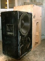
The Keystone Sub™ cabinet works well with a variety of speakers of quite different parameters and sizes.
The Keystone is named for it’s exit shape, similar to a keystone. Like keystone lens correction for off axis projection, the keystone exit corrects some frequency response problems that result when a rectangular exit is used with the particular fold pattern employed in it’s construction.

Any person wishing to duplicate my Welter Systems designs for their own use is welcome to, any person or corporate entity that would like to produce them for sale please contact me to arrange a licensing deal to avoid violation of intellectual property rights as defined in section 27 of the Universal Declaration of Human Rights adopted as international law in 1976.

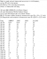
Similar in size to many 2x18” cabinets, exterior dimensions are 45 inches tall, 26.5 wide, 22.5 deep.
Weight is around 150 pounds, 68 Kilos, depending on the drivers and plywood used.
More information about the design are available in these posts:

Tapped Horn Vs. Bass Reflex Case Study - diyAudio

Horn Extender/Wave-guide for TH

Tapped Horn Directivity

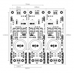
Corrected plans are available in post # 487, including parts layout, thanks to NEO Dan, with the exception that the bottom of part "F" is 89 degrees, the front of "G" is a 5 degree angle, the back of "G" is 3 degrees as shown in post #478.
The previous plans #94 and #97 (thanks Oliver) have some errors due to my providing Oliver with some incorrect numbers, sorry for the confusion.
Assembly instructions are in post #1525:
https://www.diyaudio.com/community/...ng-18-15-12-inch-speakers.185588/post-7043072
Photos of finished Keystone Subs and the bass reflex (BR) cabinet as it was used for testing are in post 1039.
Photos of the cabinet interior are in Post #99 and clarification of the 9 braces used in #206 and #451.
Distortion results are in post #12, there is a typo: The * should read: third (odd order) harmonic louder than second.
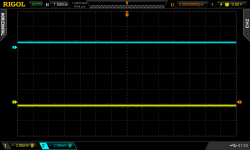
Those tests were done using 77 volt sine waves (kids, don't try this at home!!), a bit less than "full power", used the 1500W AES power specification of another B&C driver rather than the 1700 W rating of the 18SW115-4.
The upper reduction in output noted in the TH sine wave tests compared to the BR tests are due to the TH upper pass band low impedance points, while the BR has a steadily rising impedance. As the tests were started from low frequency, which has better heat pumping, and ended with upper frequencies, which don't pump as much heat from the voice coil, the upper pass band compression noted in the TH compared to the BR was due to the lower upper impedance causing voice coil heating, raising impedance, causing "power compression" at 77 volts, after less than 50% duty cycle over a few minutes time.

Hornresp inputs are available in post #96 and 130.
The link explaining how distortion was measured expired, an explanation is in post #315, and a correction in #316.
PASC built a Keystone Sub TH ("tapped horn") and a xoc1 18" TH and reported his findings in posts #114 & 115.
The lower frequency response corners using a partially covered exit, ("step down" mode) is in #262, but the description is wrong:"TH18S20" has the upper 5 inches of the exit covered with plywood, exit is 20" from bottom to top. The "step down" cover results in as much as an 8 dB increase in 30 Hz level (with only 8" from bottom to top left open), but with progressive losses in the upper bass range, so for most music the trade off is not worth the extension.

The Keystone B-Low (a low "B" note is 30.87 Hz) testing started early October of 2017, initial reports using a B&C18TBW100-4 driver are in post #1135. Photos and the response curves with the B&C18TBW100-4 and the 15” Dayton PA385S-8 and a "step down" cover plate are in post #1167.

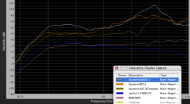
Comparative tests using the Keystone Sub loaded with an 18 inch B&C18SW115 (four ohm nominal), a 15 inch Eminence 4015LF (eight ohm), and two Eminence Lab 12 (6/2 =3 ohm) were conducted in March of 2011.

The same 16.6 inch diameter cut out was used in each case, the 4015LF used a “doughnut” adapter, the Lab 12s used an adapter that centered the two speakers on the cut out and provided a stand off so they would not slap at high excursions. The Lab 12s have a "saddle shape" frequency contour, the 96 Hz peak needs to be removed with EQ for flat response.

There are a few other peaks and dips in the response curves due to very windy conditions, often requiring waiting minutes between gusts to record responses. Test day was literally a sand storm, the bottom of the cabinet was filled with coal dust and tumbleweeds after.

All the speakers were driven with the same level. The 4015LF is actually about the same sensitivity as the 2x12 pair, since it has about double the impedance minima.

A BR (bass reflex) LAB 2x12" (36 FB) cabinet, exactly half the size of the Keystone sub is shown in the blue trace, it’s upper response is slightly reduced due to a Butterworth 125 Hz filter, all the other subs used a BW 1000 Hz filter.

As can be seen the 15.5 gross cubic foot Keystone Sub TH loaded with the B&C18SW115-4 sensitivity averages 6 dB greater than a 8.75 gross cubic foot BR.
Twice the power and drivers in a pair of BR cabinets weighing at least 40 pounds more, and occupying 2 cubic feet more trailer space are required to equal the SPL output of one Keystone Sub. The pair of BR would be capable of few dB more output below 45 Hz, the Keystone Sub +3dB or more SPL above 45Hz, more "punch" where you may want it.

There are subjective sonic differences between the TH Keystone Sub and the BR cabinet when they are driven hard enough to approach the thermal and linear excursion limits of the driver. Running subs at "full tilt boogie" is common for most applications desiring the maximum output for the minimum trailer space, and the most "bang for the buck".
1) The TH cone is under more stress at the same input voltage than the BR, this results in slightly more distortion, and the distortion spectra is at different harmonic points- the TH sounds "louder" when driven hard.
2) The BR looses LF output due to "port compression" (turbulence) relative to upper level. The TH does not suffer from any "port compression", but suffers from more upper pass-band "power compression" than the BR. The net result is the TH sounds a bit more "aggressive" (more 45-100 Hz output) at low drive levels compared to the BR, but at high drive levels, sounds "fatter" due to the LF range not reducing, while the upper range is "compressed".
These two differences are program dependent, music with wide dynamic range won't reveal the thermal problems, while compressed and droning LF content will increase both, subjectively and measurably.

Subjectively, with the same drive level, the Keystone Sub using the B&C18 seems a bit more “punchy”, more stuff falling off shelves in the shop, and more "foot feel" in the sidewalk vibrating during out door tests. The B&C18 takes full power from a bridged Crest CC2800 effortlessly, while the Eminence 4015L 15" seemed a bit “wheezy” at a lower drive level, the Eminence LAB 2x12" in between.

The Eminence speakers used in the tests are a bit more sensitive, the 4015LF would be the best “bang for the buck” output per watt/cost for low power applications. Making a slightly wider cabinet would allow two 15 inch speakers to fit, which would probably allow about 3 or 4 dB more output at the low corner, and 5 or 6 dB more upper level with only about 20% increase in cabinet size. The Lab 12s sound cleaner, and with the same voltage applied are louder than the 4015L. For those with limited amplifier or AC power or budget, the Eminence speakers are good choices for the Keystone cabinet.

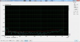
Looking at the low excursion of the Keystone vs. BR in the region from 50-90 Hz, it is evident that the cone is under a lot of stress, quite audible sounds of distress may be heard at high drive levels using lightweight (low Mms) cones.

The very stiff cones of the Lab 12 and the B&C18SW125 can take the stresses and sound clean, when pushed hard the 4015LF sounds pretty awful.

The B&C18SW115-4, though less sensitive than the Eminence speakers, will go a lot louder with a cleaner sound given more power due to its greater linear excursion capabilities, more even BL curves (the magnet "pushes" harder further), more power handling with better cooling, and a super stiff cone and suspension.

Using Hornresp simulations at rated Xmax values, (and impedance minima) average level from 35-100 Hz, the Keystone has these output levels:
BC21SW152-4 131.6 dB, 92 volts, 3.4 ohms, 2489 watts
BC18SW115-4 130.1 dB, 76v, 3.43 ohms, 1683 watts
BC18TBW100-4 127.8 dB, 59v, 3.32 ohms, 1048 watts
Eminence 2xLab12 126.3 dB, 36.5v, 2.22 ohms, 600 watts (300W per driver) 128.4 dB at 40 Hz.
Eminence 4015LF 121.9 dB, 38v, 5.17 ohms, 279 watts

The average impedance is higher than the minima, closer to the nominal rating of the speakers.
Other than the 4015LF, which did not sound good (by comparison) in this cabinet, the other drivers are capable of considerably more peak level (140+dB) without sounding bad.

I consider "safe" limiting for the Keystone sub using a B&C18SW115-4 to be as follows:

A) Use the DCR of the loudspeaker to determine the voltage setting, the DCR of the B&C18SW115-4 is 3.3 ohms, the minimum impedance of it loaded in the Keystone Sub approaches that value at Fb, where cone movement (and forced air cooling) is also at minimum.
B) The manufacturer's "Continuous Program" rating of 3400 watts is OK for peak limiting, using short time constants of a few wavelengths duration.
C) Long term "RMS" limiting with a time constant of longer than 500 ms (milliseconds) should be no more than half the rating of 1700 watts (850 watts), as AES ratings are conducted in free air (the actual power dissipated is less than 1/2 the nominal "wattage"), while driver's voice coils heat up far more when loaded in the Keystone "tapped horn" due to the far lower average impedance than the free air test. If you tend to get "heavy handed" on the volume fader playing compressed music over long time periods, use 425 watts.

If using other drivers, substitute their "Continuous Program" and 1/4 to 1/2 of the "Nominal" RMS rating for peak and average limiting settings, using the DC resistance, not the nominal speaker impedance for figuring the compressor/limiter threshold voltage settings.

Compressor/limiters will not protect a loudspeaker from excursion related mechanical damage.
Your Keystone sub should use a 30Hz 24 dB per octave Butterworth high pass filter to protect drivers from mechanical damage if amplification capable of exceeding the driver's Xmech rating are used.

Art
Welter Systems, Inc.

Attachments

  • Keystone & BR.jpg
    Keystone & BR.jpg
    21.4 KB · Views: 18,974
  • Keystone & BR subs.png
    Keystone & BR subs.png
    56.8 KB · Views: 18,355
  • Keystone,BR excursion.png
    Keystone,BR excursion.png
    22.2 KB · Views: 17,659

The VeraFi Audio A40 Amp

I have been talking a little bit about this amp on the What’s On the Bench Tonight thread, but thought it’s time to give it its own proper thread. It started as a 25W Class A amp, and now has progressed to 40W - mandatory Class A operation since the topology is SE Class A with a an active push-pull CCS based on the Aksa Lender P-Chan Complementary Aleph (ALPHA Nirvana) output stage developed by Hugh Dean and used here under license to Aspen Amplifiers PLC, Melbourne. The layout is by JPS64 which means this is a state of the art amp in terms of layout symmetry, low impedance traces, thousands of sticking vias, and careful attention to minimizing ground loops and noise immunity.

Some of the notable features that this amp will have includes:
  • Dual Monoblock design with independent power transformers and amp boards
  • Solid State Relays (SSR) for speaker DC protection similar to the RTR SSR designed by jhofland
  • SSR Soft Start with soft mains On/Standby button in front panel similar to the SFP designed by jhofland
  • Custom All-CNC milled and satin bead blasted hard anodized aluminum chassis with thick 5mm walls and massive 40mm heatsink plates. The chassis is a massive amount of aluminum on the order of 25 to 27lbs. Chassis look, shape, HMI and layout is all my own design and the 3D modeling and CAD is by Darko M.
  • Dual analog meters for output power with backlight
  • Premium Viborg copper binding posts
  • Premium gold plated RCA jacks
  • Front panel Mute switch via SSR enable
  • Automatic over temperature safety shutdown with dual thermostatic switches that activate the SSR
  • Maximum output power of 40W into 8ohms and the wonderful ALPHA Nirvana 2nd harmonic dominant distortion profile with relatively low THD of circa 0.005% THD at 2.83Vrms into 8ohms
  • Beautiful classic lines for an enduring timeless visual look
This will be offered through my XSA Labs website and we plan to offer a limited run of 25 first production units at an introductory price of $1599.

29E3D291-2737-469B-AA06-EC14F0972476.jpeg

0EEE1973-9BF0-4A8A-9BAA-77090BC39976.jpeg


We are exploring anodizing color options for the handles and heatsinks. All black is still a major contender.

11119D56-D7E2-421D-9807-DB6E0BB47A7A.jpeg


The internals will be laid out like this with the amp and its PSU mounted together on each heatsink. The floor of the amp will house the dual toroidal power trafos and also a main board let’s the SSR’s for the soft start, the main IEC soft On/Standby, and speaker SSR’s.
1674854997251.jpeg


Here is a closeup of one channel of the amp and on-board CRC PSU on one PCB assembly. You can see the temperature sensor on the heatsink. Keantoken helped with the construction and assembly of the amp PCBA.
1674855213537.jpeg


Initial testing of this amp indicates it sounds superb and the latest work is expand the chassis an extra 50mm deep to reduce heatsink temperatures and permit full 50W operation.

You can listen to it here:

Vanguard speakers
Login to view embedded media
XSD speakers
Login to view embedded media

Salas SSLV1.3 UltraBiB shunt regulator

As the beloved SSLV1.1 BiB shunt reg was getting long in the tooth, especially for NOS JFETS, I had in mind for some time now to design its successor. The goals were: 1. In production parts 2. Much simpler to set up. 3. Better technical and subjective performance.

After many breadboard experiments and two prototype PCB iterations I feel that my goals were finally met. So here comes the UltraBiB V1.3 😀

-Uses no NOS parts.
-Can do 5V to 40V output without changing a thing in its parts configuration.
-Nothing to choose and match. No tolerances in predicting its CCS limit setting.
-Has 45dB more open loop gain and many times less output impedance than 1.1
-Sounds easily better.
-Its an electrically and mechanically drop in replacement for an upgrade from 1.1

I have already given spare earlier proto boards with now deleted experimental features to few local beta testers. They are all happy by now as far as I know. The pictured board in green is the final layout in just cheapo proto that's a pain to rework and its pads vaporize in the end. It will come in proper grade black solder mask and immersion gold three sections board just like the original.

Attached: Zout plot for 150ma spare current and noise plots for 100,150,220,330,470,1000uF C2 (red 220uF). Also the rails probed on the scope for positive and negative sections. Here are typical values schematics also. I will write a PDF with instructions. Not that there is something truly special to consider when building it with the suggested parts but to describe it better as an item and to clarify details and precautions.

Updates:
31/5/18 R9's value update
1/6/18 OL sim at 100mA spare
2/6/18 Build Guide PDF added (0V0b)
24/5/19 Triplet board dimensions picture
21/6/19 The PF5102 JFET became EOL. But GB long term supply is secure. For substituting with J113 see info in post #1559
15/5/20 BC560C became EOL. But Group Buy long term supply is secure. BC559 can be used up to 30V output. BC556 for 31V-45V output.
2/7/23 LNA instrumentation measured a very low 2nVrtHz spectral noise density from the UltraBiB under real working conditions. post#3,688

Attachments

  • UltraBiB.jpg
    UltraBiB.jpg
    498.4 KB · Views: 27,127
  • UBZo150mSpare.png
    UBZo150mSpare.png
    14.4 KB · Views: 25,763
  • UBNzC2100-1000.png
    UBNzC2100-1000.png
    15.8 KB · Views: 23,500
  • PSU noise 1us 2mV.png
    PSU noise 1us 2mV.png
    32.3 KB · Views: 25,416
  • UltraBiB-Pos.png
    UltraBiB-Pos.png
    36.3 KB · Views: 27,775
  • UltraBiB-Neg.png
    UltraBiB-Neg.png
    27.2 KB · Views: 17,007
  • OL470R9100mSPR.png
    OL470R9100mSPR.png
    26.2 KB · Views: 12,837
  • UltraBiB_Build_Guide_0V0b.pdf
    UltraBiB_Build_Guide_0V0b.pdf
    556 KB · Views: 11,664
  • UBiB_Triplet_Dimensions.png
    UBiB_Triplet_Dimensions.png
    30.6 KB · Views: 8,837

The dome midrange thread

As the title states, this is a thread dedicated to dome midrange drivers, specifically any larger dome driver at least 50mm or 2" in diameter intended to be used in a 3 way or larger speaker design.

Being there isn't a good collection of data on this rather rare type of driver and its use, it would be nice to have it all in one thread. My goal was to give anyone interested in the successful design of a speaker using a dome midrange a solid starting place to gather or share the info necessary to design a new speaker or to modify an existing design to use them ie. xover, baffle modifications, etc.

If you have any specific or technical info (measurements, graphs, data, xover design, pictures, links etc) regarding your favorite dome midrange or a specific technical question, please feel free to share it in this thread.

Please keep your post to the point and avoid any strong subjective opinions. I was hoping this thread could accumulate as much relevant info as possible. Thanks in advance for any productive shared info.

Hi from Down Under

Good afternoon from Brisbane Queensland Australia. Thanks for accepting me, I have a long-standing interest in sound Hi-Fi, both valve and solid state. I'm sure this + will help me. Enormously with the collective knowledge that I'll find here.
Other Hobbies include motorcycles of which I have four, travel, music in general. Good food and wine.

For Sale Parallel LM3886 EC/Comp amp PCB

3 sets of PCB for Parallel LM3886 EC/Comp Amp. THD+N<0.0006%, Noise10uV. (see my post and measurements)

4 layers 1 OZ, 1u Gold ENIG

25USD per set ( include two PCBs, schematics, a simple build instruction, BOM) plus post 10USD for US and Canada, 15USD for Europa.

Please PM

Attachments

  • Fig266 PCB bottom.jpg
    Fig266 PCB bottom.jpg
    87.3 KB · Views: 25
  • Fig266 PCB top.jpg
    Fig266 PCB top.jpg
    132.7 KB · Views: 24
  • Fig267 1-2X LM3886 revisiting PCB1.jpg
    Fig267 1-2X LM3886 revisiting PCB1.jpg
    40.5 KB · Views: 19
  • Fig268 1-2X LM3886 revisiting PCB2.jpg
    Fig268 1-2X LM3886 revisiting PCB2.jpg
    28.8 KB · Views: 20
  • Fig269 2xLM3886 DC offset.jpg
    Fig269 2xLM3886 DC offset.jpg
    41.4 KB · Views: 23

Preamplifier Dispre 2 - JFET

After listening tests of my pre standard II JFET preamplifer, and upon requests of the builders, I have decided to design a new version of the Dipre 2 preamplifier, Dispre 2 - JFET.

The main difference is that Dispre 2 – JFET has Toshiba 2SK170/2SJ74 devices in the input stage, not the bipolar transistors that were used in the Dispre 2 V4. This modification resulted in a design of a new PCB board, as it was impossible to simply replace BJTs by JFETs, circuit modification of the input stage had to be made. At the same time, I added two resistors to enable setting of the output stage idle current. These resistors allow, in case of high technology spread of output devices, to tune output stage idle current.

Dispre 2 – JFET can be also used as a headphone amplifier, without any components changes needed.

Dispre 2 – JFET has complementary differential circuit topology with self biased JFET input stage (this topology was introduced by John Curl). This maximizes linearity of the input stage and distortion suppression does not rely only on an overall negative feedback. To remove output DC voltage component, DC servo is used.

Output stage idle current is set at 40mA, and it works in a class A up to 8V into 100 ohm load. For standard link load 600 ohm and higher, the output stage works in a class A for the whole range of output voltage up to clipping.

Dispre2 - JFET has wide bandwidth and high slew rate again, similarly as Dispre 2 V4.

Regarding PCBs, please visit a thread here:

https://www.diyaudio.com/forums/vendors-bazaar/166049-dispre-ii-pcbs-available.html

or check my webpage:

https://pmacura.cz/dispre2-jfet_en.htm

Attachments

  • d2_jfet.GIF
    d2_jfet.GIF
    13.1 KB · Views: 4,545

The 15 Song Album collection:

Hi to all,

I just want to make a album for 15 songs time over 16 minutes. It's simple. Each user has to copy and paste adding only one song to the album so in the end it's 12 songs, one per user, and each album has to have a different theme.

Whoever adds the last song of the album gets to say what the the theme for the next album will be and it starts all over again.

Songs over 16 minutes:

1. Pink Floyd - Echoes (23:31)
2.
3.
4.
5.
6.
7.
8.
9.
10.
11.
12.
13.
14.
15.
  • Like
Reactions: caisson rj

Seeking input from members Review of enhanced print thread functionality

We'll be improving the enhanced thread print function (a donation only feature) in the future.

To be sure we create a tool that does exactly what it needs to, we'd like to know how YOU use this feature currently.

Do you actually print?
Do you save it for reference and look at the file offline later?
What's important to be in there, and what's important to not be in there (eg: text or flourish that serves no information purpose but would consume ink if printed)?
Options for turning images on or off?

Right now we're not sure what's important to you. Please let us know 🙂

Heavy duty aluminum cutting recommendations please

Hello,

Since the Pass forum uses massive heatsinks and folks don’t mind miscellaneous questions, here’s mine.

I was recently given a few massive heatsinks and looking for recommendations on how to cut them (it’s DIY isn’t it 😀) since a few are too tall. They are similar to the Heatsink USA stuff but slightly more robust.

Heatsink USA :
IMG_6772.png


Mine are also about 10” wide but the rest is different;

Heatsink USA plate is 0.375” (9.5mm) thick , mine are 15mm thick. Heavy like hell 😀

Heatsink USA total thickness with fins is 2.875” (73mm), mine are 83mm.

Based on hands on experience, how would you cut such an aluminum piece so it’s usable, imperfections isn’t an issue, ugly side would be at the bottom, no problem.

Picture below;
IMG_6752.png


Thanks for your help 👍
IMG_6261.jpeg


P.s. I also received some more that are insanely massive but I will keep it for a future thread.

Introduction to "Valvalyzer" a Windows workstation vacuum tube and stage simulation software package written by Jim Reese from AmpCad.com

Hey DIYAudio community,

I'm excited to introduce Valvalyzer—a dream come true for anyone passionate about vacuum tube circuit simulation. If you’ve been searching for a tool that lets you dive deep into tube circuit behavior without the complexities or limitations of SPICE, look no further.

Valvalyzer brings together classic tube-era theory and cutting-edge computation in one free, interactive package. It lets you visualize, tweak, and understand every nuance of your circuits and transformer designs with precision and real-time feedback. Whether you’re a seasoned veteran or just starting out on your DIYAudio journey, Valvalyzer is designed to empower you to innovate, experiment, and truly make your mark.

Check it out, download it, and let’s revolutionize tube circuit simulation together. I’d love to hear your thoughts and see what you create!

— Jim Reese, AmpCad.com

The Pit Vipers

Hey,
Planning on building the Paul Carmodys The Pit Vipers.
Built a couple of amps and pre-amps with a lot of help from this amazing forum.

Recently got a workshop in my possession so I think its time to make a couple of speakers now when I have the space.
The plan is to make something quite simple and I found the Pit Vipers which seem pretty straight forward.

I do have a few questions though. (probably stupid)
1. What is the best kind of material for this kind of speaker? MDF?
2. The plan that Paul Carmody doesnt specify the thickness of the material. Can I just assume the thicker is better? Thickness would change the volume but not to any large extent.
3. He is using a 6" PVC end cap on the midrange. Wouldn't be better to make a proper enclosure?
4. How much damping should be done? All sides, top/bottom?

Volcano Soundsystem - my flight ready mini Disco/DJ rig build

Hello all. I have been trying to get a small soundsystem together for a while, without being able to make much traction on the project. Mainly due to time constraints and a lot of muddle over the config of such a system. I made many plans and acquired a bunch of parts and equipment for the new system, but it has been difficult to find an optimum due to the following requirements

Extremely portable, to flight ready
Weather resistance, some marine environment ability required
A bit of independence ability from fixed power points
Bass heavy sound
Wireless where able
Multizone compatibility
Live mics and instruments ability
Karaoke
The music is classic and modern Bollywood and West Indian

It took a while for me to note that where I needed environmental protection, the gig was smaller and with a much smaller range of inputs. I have decided to make it a pool of gear that I can mix and match for my needs. I have also had to consider some ready rolled gear instead of all DIY to neatly meet the requirements

Speakers
This is where I am trying something different. The JBL BB3 has sufficient output for the smallest gigs that I do. I acquired a Zealot S89, which appears to be similarly built as the BB3 and contains the same Racer8 driver that I have been messing with. The internal speaker setup is 2.1 with the mains section containing tweeter and midbass two-ways. I have been trying this one out over the last few days and the output is tremendous for something this small. The sound is clean and bass is forward and powerful. Battery life is impressive too. From full charge, the unit lasted a night, day and a night before turning itself off. This was at my regular indoor listening levels. Charge time seems good. My laptop USB-C charger works very well. I timed 6hrs charging time with a regular 5v2A charger and the laptop charger was lot faster, but I wasn't home to get the exact number this time

1750093620278.png


1750093818502.png


1750093937836.png


As is, the S89 will be ample for the porch, garage, deck and boat deck parties. No wires to tape up, trip up on, or pack and unpack. This connects to one of the BT TX fobs. This unit will face me as monitors while supplying the bass for the rest of the BT system. For the mains, I have bought two Zealot S97 units. These will face the floor and connect to the second BT TX fob and operate in TWS with each other. The S89 will be either used on the DJ desk or on the floor in the floor play area if I am mixing a baithak crew. This is a stop gap until I have a better solution here. Anyone who followed my Club Sandwich attempt will be familiar with this issue

I have picked up a further Zealot S51 pair to use as desk monitors for when I have the S89 on the floor. I have to get one more BT TX fob to add the console's headphone out to connect to these in TWS. One end of these speakers is designed as a base to stand the speaker up. It also contains a downward firing PR as well as an upward firing PR on the other end. Btw, the other models also contain dual PR units. I have some red stretchy nylon fabric and sew up some drawstring rucksacks for these speakers. They fit will in my booked of 4x 23kg and 4x 7kg luggage allocations. These are 100L heavy-duty duffels except for a couple of hard shells for the electronics in 7kg carry on allocations. The gear doesn't take up all of those bags

In an earlier attempt, I picked up a pair of DS18 Pro-zt69 coaxes. These are quite efficient, and I am considering tapping the tweeter and woofer wires from the S89 to drive the coaxes as active two-ways. I am reasoning that the powerful lil amp and battery inside the S89 will drive the coaxes a lot louder. To this end, I have been preparing a pair of cabs for the coaxes. I have a pair of SBA racer type PR units that may suit these cabs and coaxes too for a 60-70hz tune. At the moment the cabs are sealed types and 11L internal volume each

For external subs, I am considering a PA 18 with 4R+4R DVC and neodymium mag to reduce weight in a custom composite cab. The subwoofer amp inside the S89 sees a 2R load from a very inefficient driver. I hope that I am correct in reasoning that I can get much louder output with an 18 with coils in parallel. Tuned to the same 40Hz or so as the S89, so as not to upset any DSP filters already in use in that

If I am careful with the tapping, I should be able to retain most of the weather resistance of the unit for when it is used as is and with external speakers, I am hoping for much greater output


1750091793396.png


For local use with mains power supply, the external speakers will run off proper class d power amps. These are already acquired too

Experimental stuff
The 18" external sub thing will happen later on. Along with the coaxes, I am also building a cab for my DS18 ZR12.4D driver. This is not quite as huge as the ZXI 12" but still substantial. Will fit in my baggage allocations too for the trip coming up. For this trip, I will AB the Zealots vs the coaxes+ZR12.4D. Won't tamper with the Zealots just yet, so will run the external speakers with class d modules

1750094033838.png


The sources
A Dynabook Protégé for laptop. A Roland DJ-202 as controller and Serato DJ pro with full plugins and expansions bundle. A two into one wireless mic pair for the mic input on the DJ-202. This is my basic source setup for DJ, remix and karaoke

A Yamaha MG12XU console for accommodating more mics and instruments. A further one to one wireless mic pair for vocals from the console. This lot of flight ready sources are topped off with an Akai MPK Mini Mk3 Plus for some keys to complement the Roland TR drums built into the DJ-202

For local use, a Roland JDXI synth and a Roland MX-1 mixer completes the set

I have added two Bluetooth transmitter units to this lot. They are placed on the main and monitor outs of whichever mixer is feeding the PA

Party gear
A fog machine/disco light combo. UV black lights. LED party lights and rope lights. UV reflective backdrops. Projector and screen. Stand for mounting projector and lights

Support gear
Two powerbanks with fold out solar panels. Another pair of smaller powerbanks for the LEDs. USB hub with multiple monitor support. Laptop USB-C charger for the car to top all the things up as backup

I am sure there are some things that I am forgetting to list or missed entirely

4P1L Headphone amp

Hiya,
Been posting some pictures here and there of a new project I have started on, might as well share the whole thing. The idea started in 2018 for a regular amp (speakers), but life happened and I lost track of audio once more. The good thing is that I already have some parts that I can re-use, so in today's thinking "they are free".

Goal:
  • Headphone amplifier, 35 ohms
  • Tube, single-ended,1000-1500mW of raw power power
  • Daily beater, so no rare tubes, nothing end-game, just good music and a cool looking piece of kit
  • Must fit on desk and desk must not collapse

Tubes:
  • 4P1L
  • 2P29L or 6E6P, might also look at other wee tubes like 6Z49, 6C4S, 5842 etc

Screenshot 2025-05-26 203044.png


As I want to tinker with the driver tube a bit, the power supplies will be setup to be universal for a 250V output tube and a 200V driver, current for each tube can be up to 50mA with headroom left.

4P1L will run at 225V/30mA/-19V initially (245V/30mA B+)
6E6P will run at 200V/30mA/-3.4V, 2P29L will be 6mA/-20V, so we have 30mA/-20V as worst cases for the PSU (225V/30mA B+)

As I am betting on the 2P29L, the rest of the info will focus on this combination so as not to have two projects in one.

Supply Chassis:
  • Separate chassis for raw DC supplies to conform to the "must fit on desk" rule
  • PCBs
  • B+ will be SiC diodes, eChoke and MKP caps
  • Filaments with SiC diodes and FW/KW caps

Signal Chassis:
  • Filter for DH filaments, then Coleman regulator (current source) for DHTs
  • LDO voltage regulator for IHT
  • Passive B+ filter with RCRC to tune for both stages

Iron:
  • 2x SE OPT 10K/50mA
  • 2x Lundahl LL2763AM-40mA interstage
  • 2x Toroid 250-210-0-210-250V/330mA, 12V/4A, 12V/4A

Screenshot 2025-05-27 014544.png

signal path


Screenshot 2025-05-26 201151.png

eTracer loadline on one of the 4P1L I have tested. 1.2W max with 10K.


Step 1: Concept
Step 2: Design PCBs for test setup
Step 3: Test
Step 4: Build chassis and integrated PCBs

Attachments

  • Screenshot 2025-05-26 205917.png
    Screenshot 2025-05-26 205917.png
    66.5 KB · Views: 180
  • Like
Reactions: Fuling

Driver Choice for Volume Velocity Source

Hi,

I am looking to build a volume velocity source for measuring acoustic and vibro-acoustic transfer functions. The design will use a ~15ft 2" ID hose with a nozzle that has a microphone mounted to it to measure the source strength. The tube diameter is to act as an omnidirectional point source up to 2-3 kHz and the reason for the length is to decrease the length mode resonance so it is lower in frequency and the peaks are spaced more closely.

My question is what sort of driver should I use to drive this to high sound levels from 100Hz to 3kHz? My initial thought was to use a compression driver as that is what several commercially available volume velocity sources use. The issue with this seems to be getting something that will drive high levels below 200-300Hz. However the celestion Axi2050 seems promising. Are there better options for compression drivers that could do this or maybe less expensive options? Or maybe I would get higher levels or better results from something other than a compression driver?

I'm not very concerned with distortion levels or linearity as I will only be looking at output/input transfer functions so all of that will be accounted for. I am mostly looking to be able to drive the highest levels I can.

I'd love to hear people's thoughts on this one.

Also I wasn't sure on the right sub-forum for this so feel free to move it if I have picked the wrong one.

Force cancellation bass + OB top system

This is a new project for my friend Mark who has an enormous "great room"
30x52' with vaulted peak ceiling >20' high. The goal is not to fill the entire space with sound but the LR portion, which is about a quarter of the total floor space. Mark seeks a game-ending system, with some financial limits. He also happens to be a master metals fabricator with a lot of skills & tools, which will be brought to play.

I post this as a reality-check / peer-review of my plans.

PXL_20241104_015000865.jpg

This pic shows a fraction of the big room.

Initially, Mark wanted scaled-up versions of my LX521 clones with dual 15" SBA Nero-15SW800 in a W-frame force cancellation setup. But after examining the room again, I persuaded him that OB might be too expensive & difficult to achieve 20Hz bass at >100 dB even in just his LR space. I've heard his EV Sentry II & JBL L212 speakers in the space & there's little question the sheer size of the room is a challenge. Amending the acoustics with floating absorbers/diffusers in the ceiling (and elsewhere) is not an option due to WAF. A large rug in the LR is in the works; currently the entire space is reflective.

The current plan is a pair of 12" woofers firing sideways in opposition to each other in a sealed enclosure, topped by an OB lower mid, mid & tweeter. This would be an active system with miniDSP Flex 8 & a mix of amplifiers for the various bands, a turntable, and a Wiim Ultimate streamer/preamp.

The physical design will draw from the iconic Acoustic Research AR9 (1978-82), the modified sealed-bass LX521 I recently made for my son, and the Linkwitz Orion. Mark likes the look of my Orions, which also garner better WA. I believe I can replicate that with side-firing 12" woofers in a sealed box + a WG tweeter to reduce diffraction & control vertical directivity.

image.jpeg


PXL_20241102_012345067.jpg


orions.jpg


The drivers:

Woofer: SBA SB34SWPL76-4 Low sensitivity of 85 dB/2.83V, but 19Hz Fs, a low 79 liters Vas & 0.31 Qts allows 0.7 Q in a 40 liter (or smaller) box, with a slow roll-off easily amended by DSP. Two woofers in a box double that size could easily provide >100 dB to below 30Hz with force cancellation minimizing vibrations to the OB above. 15mm Xmax is excellent, as is the FR claimed in the spec sheet.

sb34swpl76-4-fr.jpg


Lower Mid: Satori WO24TX -- Since it will be OB & needs to move a lot of air in this big space, I paid attention to Xmax as well as effective piston area. A 12" driver might work better in the lower frequencies (as it will get quite a lot of EQ boost to compensate for the dipole cancellation effects), but this Textreme driver is flat out to 2.5kHz on axis, with little beaming to ~1.5kHz. 8.75mm Xmax is pretty good for a driver like this, and it's an opportunity to find out first hand what a Textreme driver can do. If it can be made to cross well at 2kHz or lower to a WG dome, we might be able to keep it 3-way instead of the usual 4.

20240104015821_Figure11-SBacoustics-WO24TX-4-Satori-Midbass.webp


High Mid: The Satori MW13TX is a natural choice, given the WO24TX lower mid choice. It will not be necessary if we go 3-way.

Tweeter: My favorite dipole tweeter Aurum Cantus AST2650 will get a shallow waveguide on both sides. The waveguide has yet to be made, but I've seen enough iterations of such that it should not be a big challenge, executed in 3D printing or CNC cut directly in the baffle board.

------------

Tweeter, if 3-way: Satori TW29TXNWG Textreme is a natural. The reviews of the Beryllium WG guide version in both Audioxpress & Hificompass state they are good as low as 1kHz, and there's no reason to believe the Textreme version would be much different. The back tweeter would be the non-waveguide version -- Satori TW29TXN, which is shallow enough not to require cosmetic adjustments for the hole which might end up having to go through the baffle board with the deeper WG tweeter.

One feature that will likely be adopted from the Orion is the mounting of the lower-mid 9.5" driver by its magnet to the top of the bass bin. This config positions the driver on the baffle without touching it, preventing mechanical conduction of the driver's vibrations into the baffle. There's a foam gasket to prevent spurious vibration between the baffle hole and the driver rim. The force cancellation of the bass drivers should keep most of the larger vibrations out of both the box & baffle. This method of mounting the low mid driver will complete the primary anti-vibration scheme.

orion1.jpg
-

EDIT: Forgot to mention that we'll consider adding one or 2 custom made subs, either like the one I just built with a Nero-15SW800 15" Pro driver, or the SB12" in the main speakers. The main speakers would be treated as subs (because they will be subs) and another 1 or 2 subs added to the sides of the listening area. A challenge is power outlets on one side only.

subwoofer line array

In theory and in practice, if you put multiple drivers together as in a line array, you are increasing the surface area of the cones. That in itself should be enough to push more air as if one were using a singe larger driver. However, according to one speaker designg program, this configuration does not afford any lower frequencies as if it was a single large driver.
So, could some one tell me why this would be so?
Thanks in advance.

winding P-core or air core inductors using PTFE silver coated copper teflon wire for crossovers

I am looking at winding my own inductors. I am trying to figure out how to do it without too much headache. I have access to 3d printer that can print a variety materials. I want to make fairly large 2.0mH 15A coils. Any tips? I can get fairly long 16AWG PTFE insulated silver coated copper wire scraps from local electricians I work with.

Is there any procedures available without having to redesign the wheel? I have a mini lathe. I am told to go with P-core if I can find a bobbin big enough.

I'll never need to drive more than 200W into the load. These are for PA speakers which I use at parties and outdoor electronic drum kits and synths.

Ultimately, i'd like to make something like the photo attached but better.

Thanks!

Attachments

  • preview_a34354403a921c4ef3d2f66b6960a10f(1).jpeg
    preview_a34354403a921c4ef3d2f66b6960a10f(1).jpeg
    40.9 KB · Views: 7

Towards a wideband non switching Auto Bias power amp

Syn08 (Ovidiu) said this about implementing an Auto Bias loop here:
" I haven't see a solid non switching full solution for the entire audio band, but only partial improvements over the standard solution of an acceleration cap (100nF, in your case), which is not a solution for non switching, but only a bandaid to limit the effect of the crossover mess.

Part of this lack of solutions is of course keeping the complexity within reasonable limits; Edmond's solution mentioned above, in despite of it's stability issues, is already a rather complex circuit, and I don't think anything simpler could be designed and successfully implemented."

Well, there's the challenge. A wideband non switching Auto Bias amplifier circuit that works, doesn't oscillate and blow up, and is not too complex.

To start this thread I'll post some of my findings from simulations of the LT1166 Auto Bias IC, as well as Class-i and Edmond's AutoBias2.

Feel free to post any of your ideas and simulations.

And if anyone has built a successful amplifier using an auto bias circuit then we'd love to hear how you did it, etc.

Cheers, Ian
-------------
Edit: Post summary (Edit: most recent first):
Post 303 Shows 3D views of a PCB for Post 302 circuit (now called Topology 4).
Post 302 The LT1223 again but now driving MOSFETs to demonstrate the autobias loop allows plug-in interchange of BJT's and MOSFETs. Interestingly, the MOSFET's achieve similar high BW with less drive current so 2 pair instead of 5 pair TO-92's can be used.
Post 301 The previous LT1223 CFB opamp with a CFP autobias loop is OK for 16MHz(tbc) without the CFP output stage, instead the discrete HV booster is paralleled for 50mA drive to the power transistors with a +/-9V auxiliary supply.
Post 300 The previous CFP BJT autobias loop is OK for 4MHz(tbc) with a LV LT1223 100MHz CFA with a discrete voltage booster giving low distortion.
Post 295 Bridge and current drive is easy with a HV opamp, where one load terminal is tied to input common (grounded bridge) with a floating PS.
Post 291 Current drive with a HV opamp is very easy using a resistor in series with the loads cold-side for feedback to the opamps inverting input node.
Post 287 CFP BJT autobias loop is OK for 100kHz with a 33 Ohm base pull-up to 9V. Allows a low input current (1mA) drive using a HV opamp (OPA455) with a split rail standard power supply.
Post 282 Only THT with current drive for 4 ohms suggested by Pawel.
Post 281 Current drive version for 200W into 4 ohm, Rout 500 ohms and 0.02% at 1W. Uses 2x OPA1656 LV 100mA opamp drivers.
Post 277 Class-G bridge 800W 4R using 4 slices per side for 20A peaks. Idle dissipation is reduced using Class-G plus McPherson's dissipation diverter.
Post 274 Bridge version for 400W 8R is DC input and DC output. Usescapacitance multiplier with McPherson's dissipation diverter.
Post 271 Mark Johnson query: What if the output capacitor divider capsare not exactly the same? Answer: the voltages equalise quickly due to the amps low output resistance.
Post 269 Power supply circuit to check startup with no dc blocking capacitor. Simulation shows no startup or shutdown transient to the loudspeaker.
Post 267 Input stage level shift with no dc blocking input capacitor.Uses an opamp with a -5V rail and a mirror input stage level shifterwith no signal.
Post 266 simulation using ZXT757 and ZXT857 300V complimentary pair for input stage level shift. Bias trimming calculation for output centering.
Post 257 simulation using a level shift input stage rather than a isolation transformer, allowing a standard non-floating power supply.
Post 256 mr_jj pointed out that Kenpeter back in 2010 had placed a resistor across the sensing diodes between the emitters of the power transistors to make it non-switching Class-AB! My hat is off to Kenpeter. I mention my independent finding in Post 202. The Dadson's circuit found in Post 44 here from his AES Oct 1980 article shows the same autobias sensing diode topology using a Rush spreader arrangement but with Darlington power transistors, but no resistor across the sensing diodes.
Post 254 Bench test using thean OPA1656 100mA opamp to drive power transistors with autobias without discrete driver transistors.
Post 244 Bench tests of a single channel amplifier shows -60dB THD using MUR1615 diodes and biased at 250mA. F-3dB is slightly over 100kHz.
Post 243 Shinichi Kamijo "simple TL bias" circuit is similar topology to my autobias but with a follower output stage and a non-floating power supply.
Post 235 Bridge version bench test. Two floating power supply amps on one supply, where one amp uses a small transformer to isolate the input signal.
Post 222 Tutorial on the floating power supply transconductance autobias output stage. More in Post 245 and Post 251.
Post 220 Using MUR1615 TO-220 power diodes instead of Schottky diodes gives excellent linearity. Bias can be trimmed by two resistors to 9V rail instead of two CCS's (simpler and less error prone).
Post 215 Using MJE3055 TO-220 as diodes instead of Schottky diodes.
Post 210 thru Post 214, Post 217-219. Option of using many (8-10) 1A silicon diodes in parallel per side instead of Schottky diodes so no need for a bias trim pot.
Post 205 FDC6321 CMOS stage allows high current drive without a CFP output stage.
Post 203 A prototype PCB allows stacking of up to slices (3 pair of output transistors).
Post 202 Using a HCU04 CMOS input stage with a CFP output transistors so only 1mA is needed to drive the autobias transistors. The CMOS input stage provides some gain and soft clipping and the option of thermal-SOA protection by dynamically limiting the clip level (more in Post 204). Introduced R13 across the power diodes to provides the keep-on current of 18mA in Q1 and Q2 - even when clipping. Eureka!!
-------------------------
Edit Feb 2025. Overview of development: Toward a Wideband Non-Switching Auto Bias amplifier
The challenge! “A wideband non switching auto bias amplifier circuitthat works, doesn't oscillate and blow up, and is not too complex”.Post1 aim 29 July 2021 by IanHegglun.
  • I have exceeded my expectations. A non-switching autobias topology – simple, stable, scaleable.
  • Two related topologies: 1) The floating supply version, and 2) The non-floating supply version.
  • Several diyAudio members have suggested that I provide a non-floating supply version.
  • Topology1. The floating supply version is the simplest, eg, Fig.1 below,100W into 8R, only 2 power transistors & 2 bias transistors, 2x3A diodes, a dual opamp, and a +/-9V 2W supply. Notice no Darlington driver transistors, instead two 100mA opamps operating in parallel. THD 0.1% 1W.
  • Autobias-MUR1615-MJL3281-OPA1656-1slice-1v2a-cct.png
    Topology 1: Completed Wideband Non-Switching Auto Bias amplifier with opamp driver.
  • Can be paralleled eg Post254 and bridged eg Posts274 .
  • Uses two output capacitors in series. They are forced to half the rail voltage by the feedback loop referenced to half the rail voltage by a voltage divider (R3,R19). They prevent DC damaging the loudspeaker. It's is simple, effective and reliable, with negligible effect on sound quality.
  • Topology2. The non-floating supply version. It is a modified floating supply version with an addition input stage where the input is now referenced to the negative rail. The input stage lowers distortion to 0.02% at 1W and a low output resistance of 50 milli-Ohm.
  • Autobias-MUR1615-MJL3281-OPA1656-1slice-shift-1v3e-cct.png
    Topology 2: Wideband Non-Switching Auto Bias amplifier with DC input and non-floating Power Supply.
  • An alternative bias circuit, see above Topology 2 dotted area, it eliminates the input capacitor which eliminates the long settling time at turn on.
  • The alternative bias circuit avoids a 3rd input stage which avoids a 3rd pole which requires careful frequency compensation. Both Topology 1 and Topology 2 do not use frequency compensation!
  • The loudspeaker is protected from DC damage by the two output capacitors in series.
  • Topology 2 can be paralleled eg Post257, and bridged eg Posts274 and Class-G bridge Post277.
  • Topology 2 has been simulated and a PCB is underway for bench test and listening tests.
  • Topology 1 has been bench tested eg Post244 & Post254 and a listening test Post157. The Topology 1 PCB needs updating for an opamp.

  • Topology 3. See Post287 and Post291.
  • CFP BJT autobias loop is OK for100kHz with a 33 Ohm base pull-up to 9V. Allows a low input current(1mA) HV opamp (LT6090-5 or OPA455) to be used with a split railstandard power supply.
  • Topology3.jpg
  • . . . . Topology 3. Wideband Non-Switching Auto Bias amplifier with DC input and non-floating Power Supply and no auxiliary ±9V supplies.

  • Topology 4. See Post301 and Post302
  • Using a LV LT1223 CFB opamp with a CFP autobias loop is OK for 16MHz(tbc) without the CFP output stage.The opamps discrete HV booster is paralleled for 50mA drive to the power transistors. The trade off is the ±9V auxiliary supply.
  • Topology4.jpg
  • Topology4. Wideband Non-Switching Auto Bias amplifier with DC input and non-floating power supply and no CFP power stage, instead the auxiliary ±9V supply and higher current opamp booster stage.

Attachments

  • Like
Reactions: X.G.

Starkit 12-22A needs Meter

Hi guys I just picked up a Starkit 12-22a tube tester and it needs a meter , does anyone know of a company that sell something that may work . (500au ) it's a real nice tube tester and would hate to scrap it for a simple meter .I tried using it with a volt meter attached to the meter outputs and it seems to be working .. thanks for any help .. cheers Roger
  • Like
Reactions: anatech

Need help with Sansui 1000A phono boards

Does anyone have a component map for the phono boards in a 1000A? I need something that has the circuit boards printed out with designators on it for the parts. Also the 7 or 8 IO tabs on the bottom of the boards. What each leg is and where it goes. I could map it out the hard way but was hoping someone may have already done the hard work already. Also I am looking for a small circuit I can replace the stock circuit with. Preferably with improved performance.
Thanks for the help. It would be nice if Sansui had maps of the boards like most of the other brands do.

Ported cabinet for guitar amp

Hello,
I am trying to build a cabinet for my guitar amp. I have build other cabinets but this time is different and i need some help. I need to build a ported cabinet, like the tl806 but the speaker i have is not the famous electrovoice el12.
I m going to use a jensen tornado classic 100 8 ohm istead.
IMG_1011.jpeg

I have used an online calculator to get me in the ballpark, here the results

IMG_1010.jpeg

Now, my doubts, the cabinet volume suggested is huge, 126 liters it is going to be oversized for guitar amp 1x12.
Do you think these results can be trusted or should i use a better source?
I know the tl806 cab design has slots and not pipes for the bass reflex but i don t care, i m not trying to clone the design, just the concept.

Has anyone ever had either incorrect parts or out-of-tolerance parts from Digi-Key/Mouser?

Just thought I'd toss the question out there... about to populate a bunch of boards with resistors and caps from Mouser, and I'm holding off until my DER EE DE-5000 arrives so I can check each one before populating. Doing that would also make sure none of the parts are faulty.

I don't think I'm going to change my mind about that but I'd like to know what other people do/think.

Sealed vs. ported enclosure midwoofer SQ!

I suspect this topic is covered dozens of times, but I couldn't find the answer I'm looking for.

So I have a speaker design that, in any case, woofers will be crossed to a horn around 800 Hz. This is constant. I'm either gonna use a single Faital 12RS430 in a 70L ported box and have decent F3 and 800 Hz covered, or I will use a woofer like Fostex FW 305 in a sealed box and use a second woofer starting from 100 Hz to the low end.

My question is about the quality of this 100-800 Hz. Which one might sound better? More resolution. The goal is not higher SPL, just more mid/low-mid clarity. Using a low Mms midwoofer vs. a heavier woofer (although Faital's Bl/√RE is higher...). If you have any woofer suggestions that can beat the FW305 in an even smaller box, please don't hesitate.


Thanks for the answers in advance!

Investigating port resonance absorbers and port geometries

thread index at the end of this post!

When planning, simulating, building and measuring bass reflex enclosures for 2-way speakers one difficulty is dealing with port resonances in the midwoofer’s passband.

I thought it should be possible to absorb resonances with Helmholtz resonators in/at the bass reflex port.
Obviously I am not the first to come up with this idea, but I also didn’t find very much about it on the internet.
Thus I decided to make my own measurements, see the following posts!

some web references:​

Short thread about this issue on diyaudio. note that the thread starter wrongly refers to the "1/4 wavelength resonance" of a port. This is not correct! The fundamental resonance of an open tube happens at the frequency that has a wavelength equal double the tube length.

A german thread about port tube resonators.


various web references for resonance of open tubes and helmholtz resonators:

https://en.wikipedia.org/wiki/Helmholtz_resonance

https://en.wikipedia.org/wiki/Acoustic_resonance#Open_at_both_ends

https://www.physicsclassroom.com/class/sound/Lesson-5/Open-End-Air-Columns

https://en.wikipedia.org/wiki/End_correction

http://troelsgravesen.dk/vent_tuning.htm (including end correction values!)


calculating resonance of bass-reflex port (open tube resonance):​

occurs at frequency that has half wavelength equal to end corrected reflex port length and respective frequency multiples.
Oscillation node (pressure maximum) is at center of port (or further divisions for multiples).
pressure absorber works best at the respective node.

Option 1: tube absorber​

Simple tube, one end closed, it should thus have roughly half the length of port for absorbing resonance of port fundamental; can either be parallel (and inside) the port or 90° perpendicularly mounted at port. Open end should be located at half port length.

Option 2: Helmholtz absorber​

Mounted at half bass reflex port length, connected by its own small Helmholtz port to the bass reflex port

-------------------------------------------------------------------------------------------------

Thread index

#3 - first resonance absorber tests with tube test setup
#5 - decay plots of test bass reflex box
#8 - resonance absorber results by @augerpro
#11 - link to a relating message by @rdf including link to roozen/philips-paper
#19 - new parallel 6th order bandpass test box for further investigations
#22 - dealing with enclosure resonances
#25 - chuffing audibility test
#42 - particle photos (using water sprayer)
#48 - port 2 variants and measurement results
#50 - port stalling test
#54+55 - influence of smoothed port flange
#56 - port 2 impedance results
#58 - port resonance absorber test
#81 - link to bryce doll paper by @Hearinspace
#103 - port 2 variants resulting in the same tuning frequency, with geometry drawing
#104 - photo of port 1 variants
#141 - port wall stiffening influence
#157 - port 1 variants response measurements
#159 - chuffing RTA measurement of straight port 1
#161 - chuffing RTA measurement of rectangular curved wall port and big 3d printed port
#165 - chuffing RTA measurement of flat port and small straight port
#166 - resonance absorber setup
#167 - measurment of resonance absorber lenght variations
#202 - resonance absorber filled with melamine foam
#206 - chuffing RTA measurement of 3d printed port with resonance absorber
#214 - influence of port diameter/dimension for enclosure resonance transmission
#228 - small 3d printed port drawing and measurments
#230 - testing noise of roughened port surface
#236 - port with resonance absorber documentation by @Kwesi
#249 - chuffing RTA measurements in singe dB steps (small 3d printed port)
#251 - separating resonance absorber from the port with latex membrane
#288 - link to salvatti devatier button paper
#302 - explanation of boundary layer thickness by @andy19191
#310 - impedance measurements for port 1 variants at different input levels
#320 - "progressive port geometry" concept
#324 - progressive geometry port measurements
#328 - progressive geometry port length correction
#329 - progressive geometry port impedance measurements at different levels
#330 - progressive geometry port response
#331 - progressive geometry port chuffing RTA measurement at 100 Hz
#341 - output level measurement / comparison
#349 - is airspeed the main chuffing factor? progressive port chuffing RTA measurement at 50 Hz
#350 - new particle photos
#352 - explanation of turbulent air motion by @andy19191
#363 - relating chuffing to particle displacement
#367 - first GIF-excepts of 120 fps particle videos
#390 - port variants with sound recordings by @Tenson
#391 - correct port particle displacement calculation formula by @David McBean
#395 - (1) first slow motion video: hard edge port
#407 - (2) second slow motion video: flared port
#434 - flange variant video
#438 - (3) third slow motion video: progressive geometry port
#448 - influence of air particle displacement for the excitement of low frequency noise
#449 - differences of a big and small (optimized) port for a small 2-way midwoofer
#460 - (4) fourth slow motion video: small straight hard-edge port
#468 - small very flat port - checking for boundary layer flow resistance
#503 - how to calculate the strouhal number using max port air velocity data, CORRECTION see #591
#504 - water tank simulation
#522 - @Dmitrij_S Karlson couple port
#526 - flared port geometry definition
#529 - 2 way speaeker test ports to be measured ...
#531 - ... response measurements ...
#546 - ... chuffing measurements (RTA) ...
#591 - correct calculation of strouhal number, related to peak-displacement instead of p-p- displacement (thanks to by david mc bean)
#595 - how to find a suitable port exit diameter using the Strouhal number (corrected version!)
#616 - first beta version of a simple excel sheet for tuning calculation of NFR=0.5 ports
#621 - relating the strouhal number to compression and distorsion
#624 - parametric fusion 360 model for a NFR=0.5 port by @augerpro
#627 - augerport with resonance absorber by @augerpro
#646 - parametric NFR=0.5 port model for freeCAD, including STEP and STL model
#652 - announcement by @David McBean: stouhal curve included in the port exit air velcity graph.
#654 - how I make my 3d printed ports
#680 - chuffing/noise audibility comparison: straight and flared port
#704 - big collection and evaluation of 3 speaker and 14 port variants - proposed MID PORT STROUHAL NUMBER (MPSN) parameter
#747 - updated excel calculation tool with correction and variable NFR ...
#748 - ... and the imperial version of the same calculator
#753 - comparison ports vs passive radiators
#811 - compressing the optimum geometry definition to two relevant parameters
#812 - The breakthrough: Finding compression behaviour patterns
#847 - Iterative port geometry optimizer tool


(will be updated)

A New EC-Composite LM3886 Amp

This Error-Correction/Composite Combo amp is based on Mr Evil "Unnamed feedback method explored" and Nickolay Shvydky "My ZD-50 ultralow distortion chipamp"

Output power at +/-29.5V: 8 ohms clip at 42W, 4 ohm clip at 65W. It is very stable in both EC and Comp mode. Ans it behaves very well after clipping.

I could only measure its THD+N very roughly using Focusrite Solo 3rd, which has a minimal line-out and line-in THD+N of 0.002%.

U1 is OPA1655 and U2 is OPA828. For error-correction(EC) mode, RV1 was set at 330ohm. For composite (Comp) mode, RV1 was set at 680 ohms.


Final Remarks

Today marks the completion of my 6xLM3886 PBTL (Parallel Bridge-Tied Load) amplifier, now fully assembled and installed in its case. Hearing music flow from the amp for the first time was an incredibly rewarding moment.

This has been the most time- and resource-intensive DIY amplifier project I've undertaken. It all began with a spark of curiosity after discovering HAYK’s thread, which then led me to explore designs by Nickolay Shvydky (ZD-50), Mr. Evil’s EC-correction, and Tom’s Modulus series.

I initially started with the ZD-50, but its complex compensation network proved daunting. I decided to pursue a simplified approach. After many hours with LTSpice, I developed a streamlined version of the design, which is shared below.


The first prototype used through-hole components and served as both a learning and testing platform. Getting the amplifier stable took significant effort, with a variety of issues encountered and resolved along the way.


Next came the 2xLM3886 parallel version, which helped me better understand the parallel operation of the LM3886. It also served as a base for further schematic refinement and testing.


Throughout development, I upgraded my test equipment for greater precision, allowing for more accurate measurements and analysis.


The final goal was this 6xLM3886 PBTL amplifier. With the knowledge gained from the earlier versions, I was able to optimize the circuit design, select key component values carefully, and fine-tune the PCB layout. The result is a high-performance amplifier with impressive specifications:


  • Power Supply: Hammond 1182T24 625VA transformer (24VAC/13A dual secondary), DIYAudio Store Universal Power Supply board, and 140,000µF of filter capacitance
  • Output Power:
    • 175 W into 8 ohms @ THD+N 0.00023%
    • 240 W into 4 ohms @ THD+N 0.00042%
  • Residual hum/noise floor: ~10 µV

(Note: These measurements were taken using amateur-grade equipment under informal conditions. They are provided for reference only and should not be interpreted as certified or industry-standard specifications.)


I’ll now spend some time listening to the amplifier and enjoying the results. Meanwhile, I plan to revisit the earlier versions and design optimized PCBs for them as well.

(I made 5 sets PCB, minimal number of ordered sets, of the amp, there are 1 sets left for sale, see swap meat)

2xLM3886 EC/Comp
+/-32V 80W 4ohm, THD+N<0.0006%, Noise 10uV.

Attachments

  • Fig76-3 Min EC-Comp LM3886.jpg
    Fig76-3 Min EC-Comp LM3886.jpg
    160.5 KB · Views: 1,669

3-way to active - Hypex FA253 - learning project

Hello, All!
Just joined today as I found a very useful guide here on using Hypex Filter Design, thanks to DannerD3H.

I have always been a music and audio fan and find acoustics and speakers particularly fascinating. I always wanted to design and build my own speakers but never got to it, mainly due to lack of space to use for woodworking (I live in a small flat). But still decided to go for it. I will work around the difficulties somehow. If there is a will, there is a way.

I have reasonable understanding of audio, electronics and design process and ok to use my hands, but I have almost no experience, so face a steep learning curve.

First thing I did is buy the Loudspeaker Design Cookbook. Reading it now. Learning curve.

I have a pair of old slim floorstaders (description to follow) that I intend to convert to actives. This will help to initially avoid much woodwork, while still learning about drivers, crossovers and amps and box interaction. This will be done in two steps:

Step 1 - add Hypex Fusion amp and use existing drivers and enclosure as is

Step 2 - replace the drivers for better specced ones, modify the box

This will hopefully take me to a future point of fully building larger speakers and maybe a sub. One day.

So far I have bought a Dayton UMM6 mic, a Fosi V3 amp and just about managed a few measurements in REW of the speakers in passive form and of individual drivers. I managed to install on old version of HFD software on an old Win XP (!) laptop and hope to use that to program the FA253s when they arrive later this week.

I do stumble a lot and have lots of questions and definitely need some help. I will be asking here and would appreciate any help from the more experienced members.

I will make a post with the existing speaker details and maybe a few other things I am struggling with.

FWIW I do have some forum history on a couple of HiFi forums: Hifiwigwam and Audiosciencereview.

So, wish me luck.

Introducing "KRONOS" a vintage inspired 2-Way.

Hello everyone!
I've recently finished my vintage inspired 2-way design and figured I'd share the journey here for any fellow members who may be interested in the concept or even building it for their self.

Soooo. Let's see it! What is it? Kronos is a sealed 2-way design utilizing the SEAS A26RE4 10inch Woofer and the Visaton FRS 5x-8 2inch in a WG.


01.png

Wait, isn't that Visaton driver a full range? Isn't this more of a "WAW" design? Yes, the Visaton is in fact a full range driver but it's actually being utilized as a tweeter in this design. It's mounted in the Visaton WG and integrates perfectly here with the SEAS woofer.

Isn't there already a similar design for this woofer? The A26? Yes, there is. However the tweeter for that design is rather pricey at $350+ each, while the cost here is $14 for each driver and around $19 for each WG currently on Parts Express. (Other options available as well, see below)

Okay okay, enough with the Q&A, let's get into how this came about and details of the design.

Introduction:

The Kronos speaker build was born from a sense of nostalgia—rooted in childhood memories of sitting in front of my dad’s hi-fi system, mesmerized by the towering loudspeakers that filled the room with sound. Those classic designs, with their large woofers and cone tweeters, left a lasting impression. They had a presence—both visually and sonically—that felt larger than life. With Kronos, I set out to pay homage to that era and those experiences, blending the soul of vintage loudspeakers with the clarity and control of modern design. It’s a tribute to the sound that sparked a lifelong passion.

Driver Selection:

To bring the Kronos concept to life, I carefully selected a driver lineup that reflects both the spirit of vintage design and the performance of modern components. For the low end, I chose the SEAS A26RE4, a 10" paper-cone woofer known for its rich tone, effortless bass, and smooth upper response. It’s a direct nod to the classic wideband woofers of the past—capable of anchoring the system with warmth and authority.


For the top end, I went with a more unconventional approach: the Visaton FRS5X, a small full-range cone driver, paired with the Visaton WG 148 R round waveguide. This combination offers a controlled dispersion and a pleasantly natural tone that echoes the voicing of vintage paper cone tweeters, but with improved focus and clarity. To mount the FRS5X, I simply centered it on the waveguide and drilled my own holes—an easy but effective way to create a tweeter solution that stays true to the DIY spirit and captures the character of old-school designs.


Worth noting: With the rise of 3D printing and modern fabrication techniques, custom waveguides for drivers like the Visaton FRS5X are now readily available. For those looking for a more refined or drop-in solution, Heissmann Acoustics offers a purpose-built 3D-printed waveguide specifically designed for the FRS5X. It's a great option for builders who want to simplify the mounting process while maintaining the same compact format and controlled directivity.

HA_WG_169_FRS5X_c.jpg


Enclosure Details:

The SEAS A26RE4 woofer is housed in an approximately 85-liter (about 3.0 ft³) sealed enclosure, giving it ample volume to breathe and deliver deep, full-bodied bass with natural roll-off—true to the character of classic hi-fi systems. This generous internal volume helps the woofer operate efficiently without excessive low-end boom, maintaining a balanced and effortless presentation.


The Visaton FRS5X is isolated in its own 1-liter (0.035 ft³) sealed chamber. This small compartment ensures that the mid/tweeter remains unaffected by pressure changes from the woofer, allowing it to perform cleanly and consistently.


Throughout the cabinet, adequate internal bracing was incorporated to minimize panel resonance and structural flexing. The result is a rigid and acoustically inert enclosure that supports clean, undistorted output even at higher playback levels.

Untitled.png


Crossover Details:

The Kronos crossover began as a theoretical layout, designed with target values based on driver behavior and desired voicing. From there, it was refined entirely by ear, with countless hours of listening and adjustment until the final values locked into place. This process allowed the system to reach a balance that felt natural, dynamic, and emotionally engaging—true to the character I set out to achieve.


The SEAS A26RE4 woofer, a modern version of the W26 used in classic designs like the Dynaco A25, has a naturally smooth roll-off that doesn’t strictly require filtering. That said, I chose to add a small 0.33 mH series inductor to gently tame the upper midrange, making the speaker more forgiving and enjoyable at higher volumes—reducing the risk of harshness or “shouting” without robbing it of presence.


For the FRS5X tweeter, mounted in a waveguide, no series resistor was needed. The waveguide not only improves sensitivity and dispersion control but also helps the FRS5X blend naturally with the woofer. Without the waveguide, I would have added around 1 ohm of series resistance to balance its output. The high-pass network is essentially first-order, using a capacitor for the main roll-off. A parallel inductor was added to keep the tweeter’s upper resonance from bleeding through—simple, but effective.


While a textbook solution might call for an RCL (resistor-capacitor-inductor) network for perfect impedance correction, I found that in practice, a single coil did the job just fine. An optional overall impedance compensation network was included for the sake of completeness, but it's more a nice-to-have than a necessity in this build.


In the end, the crossover reflects the spirit of the whole project—minimalist, purposeful, and guided by listening above all else.

Kronos Crossover Schematic (3D).png


CROSSOVER PCB:


To make this project more accessible for others—especially those new to DIY loudspeakers—I went a step further and designed a dedicated PCB for the crossover network. Rather than relying on point-to-point wiring or a perfboard layout, this custom PCB ensures clean, repeatable assembly and proper part spacing, helping reduce the chance of wiring errors and making the build experience more enjoyable.


The board is laid out with component footprints matched to the actual values used in the final design, and it includes clear labeling for easy reference. Whether you're a first-time builder or a seasoned DIYer, this PCB simplifies the process and makes it easier to achieve consistent results.


I’ll be including a download link at the end of this presentation with everything needed to build your own pair of Kronos speakers—including crossover schematics, PCB files, enclosure plans, and additional notes gathered throughout the build.

PCB_DIM_michaelping532-1.png


Finished Speaker:

Here’s a look at the finished Kronos speaker. Aesthetically, I realize this look might not be for everyone—but that was never the goal. I wanted the finish to reflect the spirit of the project: cheap, fun, and bold. The result is something unique, eye-catching, and artistic.


I’ve had a few people ask how I achieved the finish, so here’s a quick breakdown:


  • I started with a roll-on bedliner called "Total Coat" to create a tough, textured surface.
  • After that, I applied a Rust-Oleum yellow paint as the main color.
  • For added visual interest, I used Rust-Oleum Black Marbling spray, which creates a random web-like texture and gives the surface a more dynamic, artistic feel.
  • Finally, I sealed everything with a Rust-Oleum matte clear coat, which helps protect the finish and reduce glare.

It’s not a high-end veneer or mirror-gloss lacquer—but for a fun, rugged speaker with personality, it gets the job done. Cheap, effective, and satisfying to see come together.

IMG_2236.JPG


Final Measurements:

Below you can see the final measured response of the Kronos design. The results highlight just how well the Visaton FRS5X in a waveguide and the SEAS A26RE4 woofer integrate—especially considering the simplicity of the crossover network.


The response is impressively smooth, with excellent tonal balance and a natural transition between drivers. The waveguide not only improves the FRS5X’s efficiency and dispersion but also allows it to blend seamlessly with the larger woofer, avoiding the typical disconnect you might expect from such different-sized drivers. The minimal crossover does just enough to shape the response where needed, while preserving the raw, engaging character of the drivers.


This measurement validates the listening impressions—a coherent, dynamic speaker that stays true to its vintage inspiration while performing with modern finesse.

KRONOS Measurements.png


Listening Impressions:


The final implementation of the Kronos exceeded my expectations. While I didn’t build these to be the ultimate reference monitor or the “end-all-be-all” speaker, the result is something that sounds exceptionally good—better than I had originally imagined.


The bass performance is particularly impressive, with deep, full extension that's further enhanced by room gain and proper placement. The SEAS woofer really shines here, delivering weight and authority without muddiness.


Tonally, the speaker holds up well across a wide variety of genres. So far, I've enjoyed everything from Rock, Jazz, Pop, Hip-Hop, EDM, to Classical, and the system has handled them all with confidence. The highs are clean without being harsh, mids are clear and natural, and the overall balance feels cohesive and engaging.


Even at very high listening levels, the speaker maintains its composure, with no sense of strain or collapse—perfect for those nights when you just want to crank things up and let loose.


I’ve also had a few friends over to hear them, and the reactions have been consistently surprised and impressed. There’s something satisfying about watching someone sit down with no expectations, and then light up the moment the music starts.

In Conclusion:
The Kronos has accomplished everything it was designed to do—and then some. It’s a speaker that brings together nostalgic inspiration, modern performance, and hands-on DIY fun in one cohesive package. I’m genuinely proud of how it turned out, and I know I’ll be enjoying these speakers for many years to come.


For those interested in diving deeper into the design—or even building a pair yourself—I’ve put together a comprehensive resource link below. This presentation has only scratched the surface, and the download includes detailed plans, crossover files, PCB layout, measurements, and more.


If you have any questions or run into issues, don’t hesitate to reach out. I’m always happy to help fellow builders in any way I can.


Thanks for taking the time to check out my project—I hope it inspires you to build something of your own.

LINK TO KRONOS BUILD PLANS: https://drive.google.com/drive/folders/1Kpa-w3JEGQmEdG6RKKRCQnM0pMenjgjl?usp=sharing

Wondom Jab5 fan noise

Hello. I'm using a Jab5 4x100 dsp amp board on a project. The SQ is acceptable for the use even if there is some background tweeter hiss. The fan noise is the real issue. I'm wondering if anyone has had any long term experience running the board with the fan disconnected and/or removed. Has it lasted without the additional heat dissipation? Also contemplating adding a resistor to reduce the fan output.

Post your wildlife pics here

In the fall of 2023 my family relocated to North Western Connecticut which is an area that is a bit more rural than we had experienced previously.

One of the daily joys of living in this new area has been the almost daily sitings of wildlife…everything seemingly wanders into our yard when we least expect it…deer, bears, coyotes, hawks, eagles.

One of our favorite almost daily sitings is the Fantastic Mr. Fox who has set up residence on the edge of our property the past two years with Mrs. Fox and produced a brood of 4 pups both years.

The pups usually start venturing out some time in April. Most likely mom is trying to give them some practice at hunting mice for themselves. They are seen playing in and around the pool and rocky bank towards the bottom of our property.

I’m lousy on the draw with my phone camera. I’m sure some of you guys are much better.

Post a pic of some of your furry wild friends that you caught a glimpse of.

IMG_6467.jpeg


IMG_6440.jpeg

Danley Cohearix

Looks like it's That Time Again, where I make a semi-educated guess about a new Danley invention.

Been at this for a while, here are my previous threads:

1) This one didn't get a lot of attention, but my thread on the Genesis horns provided a TON of information on the Jericho Horns, the Paraline, and the midranges used in both Danley Sound Labs and Sound Physics Labs speakers: https://www.diyaudio.com/community/threads/i-dont-understand.133745/

2) Here's the OG thread on making Unity Horns: https://www.diyaudio.com/community/...ge-cone-for-bandpass-mid-in-unity-horn.88237/ thanks to @Puggie and @GM for getting that one going.

3) Here's the "main" Paraline thread: https://www.diyaudio.com/community/threads/square-pegs.217298/ And the secondary one: https://www.diyaudio.com/community/threads/stargate.225832/

4) Here's my reverse engineering of the Danley Matterhorn: https://www.diyaudio.com/community/threads/old-school-horn-vs-modern-vented-box.250032/post-3794298

Which diyAudio designs are available on Aliexpress etc?

Hi all

There is some great contributions with open source designs and gerbers on diyAudio. The hardest part is deciding which one to build 🙂.

I think some of these have made their way to Aliexpress sellers. Sometime ago I came across the Ultimate Fidelity 100w amp on AE which appeared to be one of the revisions from the thread here.

Does anyone know of any boards/kits/amps from AE based of designs from here?

What's the problem with modern proper loudspeaker cabinets decoupling?

Hello,
In a world of engineers i'm a tad shocked to don't see any good decoupling, the mecanical engineers are not all dead since i've recentely be teached by one of them and my last school teacher was also an engenneer (with a PhD in mecanics)... he was young 25 years ago.
People are using CAD and FDM printers here and no one seems able to decouple convenientely a loudspeaker, could you say what i don't understand ?

Aliexpress is full of strange spikes and ridiculous spring systems, are we all idiots ?

Here is a SMR for a microphone :
rode-smr-premium-shock-mount-1.webp
  • Like
Reactions: Wright and abstract

Wordle

When I was young, we spent hours on end playing what we called word game. Same rules but it was always 4 letter words.
I was introduced recently to this new sensation and tried it today. Now I know it's beginners luck, but first time out I got it in 3 words.
I think I'll try again and let it bring me back to earth.
Who else is doing this?

Attachments

  • DSCN8507.jpg
    DSCN8507.jpg
    65.5 KB · Views: 1,639
  • Like
Reactions: STOXX

For Sale Apex FH9 A/B Dual mono block Amplifier.

This is a pair of Apex XRK Audio modified FH9 boards, Dual mono blocks that run in AB
50 watts 8 ohms they are dead quiet and sound fantastic
The amp uses 2 of the Prasi CRC power supply units,
Includes both boards the Heatsink 2 Antek 300va 25v Transformers
Prasi PSU CRC Boards
Which can also be used for Class A amp boards as well.
Use them as is on Baltic Birch Board,
Or put them in a nice enclosure and you have a fantastic sounding amp ready to go.
$260 for all local pickup only.

Attachments

  • IMG_0033.jpeg
    IMG_0033.jpeg
    1.1 MB · Views: 139
  • IMG_0030.jpeg
    IMG_0030.jpeg
    904.5 KB · Views: 134
  • IMG_0353.jpeg
    IMG_0353.jpeg
    1 MB · Views: 138

Treat termites in my speaker enclosure

This weekend I found termite droppings on the floor underneath my mid/hi speaker box. I thought I got rid of the termites when I disposed of my old TL sub woofer but apparently they migrated to the mid/hi enclosures.
The enclosures are constructed of Okoume plywood. This plywood is not water resistant. I can wet it, but not for too long a time. These enclosures are simple small bass reflex boxes of about 30x30x15 cm. Easy to replicate with water resistant plywood. But not as nice to see.
The new TLs I sprayed with "Ortho Home Defense Termite & Destructive Bug Killer" before assembly. I have no signs of termites yet, but that doesn't guarantee they are not infested.
I am really worried about the termites migrating to my new TL subs which are much larger and harder to rebuild. So preferable I treat both the small enclosures and the TLs equally. The first first to expunge, the second to prevent.
Any ideas of how to treat for termites? Since the speakers are in a dry room, part of the time air conditioned, no moisture, I assume these are dry termites. I never see a sign of the insects or wings. Only excrements. There are no environmental or import restrictions on any chemicals. As long as I can purchase from Amazon.

Ekta Grande or Ekta 7741

hello all,

i need new speakers, so i want to ask your opinions about this 2 DIY Kits.
The baffle at the ekta grande looks like a promise for a good soundstage.
The 7741 use the newer illuminator chassis.

Ekta Grande

Ekta-7741

i want to go for passive xover this time, even i own a pair of hypex 123 amps which would reduce the cost.
they are a good tool when its comming about making the xover fast and easy and active speakers are always great,but aside of this really big benefits im not so happy.

My room> 5,22m in lengh and 3,85 in width
the speakers are placed left and right of a lowerboard where a 65" TV is. (yes,not perfect, i know it has an impact on the reflections)

on the ceiling i have 18 pcs 50x 100cm Basotec panels which are 5cm thick.
on the opposite site of the speakers is the couch and above that a 240cmx140m acoustic picture which is filled with 5cm basotec panels.
so the treble is well damped, maybe a little to much 😉

Music, well all kind music except jazz.(classic is really rare, maybe one or 2 times in a year.

what i like on speakers, details and more details, a good seperation between instruments.silent things to hear that get lost on cheap shoutboxes.

my past system was a 4 way active seas excel system. with an 35cm baffle.

So, what do you think are the pro and cons of those 2 Kits ?

EL34 Baby Huey Amplifier

Hello EL34 Baby Huey builders,

As suggested by SCD in the following thread : http://www.diyaudio.com/forums/tubes-valves/72536-el84-amp-baby-huey-217.html#post5533779 I am starting a new thread specially dedicated to the building of Baby Huey amplifier based on my PCB which has been produced in more than 330 pieces and is still requested by many tube amplifier fans in a possible future Group Buy 4 : http://www.diyaudio.com/forums/group-buys/312869-gb-baby-huey-pcb-42.html 🙂

I will put in this thread all the information available about the assembly of the EL34 Baby Huey amplifier and some of the auxiliary board that I have used or designed to add some features to the amplifier. I must tell you that I am not in professional amplifier business, this is just a time consuming hobby for me and, as you will see, English is not my first language and I have sometimes difficulties to explain things correctly, sorry for that but at least you will understand easily schematics, pictures, B.O.M., etc... 😀

History

All that started about two years ago when I read the http://www.diyaudio.com/forums/tubes-valves/72536-el84-amp-baby-huey-217.html#post5533779 post from "gingertube" ! As I was interested by the shunt feedback concept that I didn't know I wanted to test it and decided to build the simplest version with two PCL86 tubes. Since I am very bad in point to point wiring, I made a small PCB. This amplifier was so good that I decided to continue my quest and, since the ECL86 or PCL86 were unfortunately no more produced, I made a second PCB for the EL84 version which needed a third tube, a 12AX7 (ECC83) for the input stage and added MOSFET with current source to drive the output tubes. This amplifier was very good and I was very satisfied by the MOSFET driver stage, but I was also a little bit frustrated by the limitation in power, about 12 W, and the fact that I could not use different power tubes...

To solve this problem, I made an identical version but with octal socket to accept many compatible tubes from the 6V6 to the KT88 and the EL34 Baby Huey was born ! Following the presentation of this solution on the diyaudio forum some members asked me if I could sell the PCB, I had never done this before but since the moderator move this discussion to the Group Buy forum I have received several request and started a GB1 with a target of 50 boards but finally closed it with 80 PCB ordered 🙂 I had to send them Worldwide and to learn how to make PayPal invoice... Later others readers asked me for more board and I offered a second and "last" GB2 which finished with 120 boards ordered !!!

Later, since there was still a strong demand, I asked Prasi, to whom I have bought a CRC power supply PCB, if he would accept to manage a third GB and he kindly accepted 🙂 He also suggested to make 2.4 mm boards for better rigidity. Now 120 more boards have been ordered and are in production and there is already 20 PCB's in waiting list for a possible GB4 ?

Documentation

In this first post I will enclose some of the latest documents available for building the EL34 Baby Huey and I will add more in next posts depending of your questions.

You will find the updated BOM in the GB letter, the latest schematics, some building recommendations, how to connect and to adjust the amplifier and several pictures showing the PCB assembled on top side (big components go on bottom side), a 6CA7 board fully assembled in test and finally the EL34 Baby Huey in its enclosure nearly finished (two vu-meters are still missing).

More pictures and data will come from all the people who have built this nice small amplifier. It is a very nice project for those who have never made and listen a tube amplifier, but remember there is some lethal high voltage (up to 500 V) and you should be very careful when you work on it :redhot:

Have a nice time building the EL34 Baby Huey...

Best regards,
Marc

Attachments

  • Like
Reactions: aroS3

New Purifi Tweeter Data Sheet

Hi all, here in Europe there is at least one shop where i could pull the spec sheet

https://doc.soundimports.nl/pdf/brands/purifi/PTT1.3T04-HAG-01/PTT13T-HAG-01-Datasheet.pdf

The application information is good, never seen something so good explained from other vendors

Screenshot 2025-06-15 092010.jpg


So far - so good, Stefano

P.S.: this is the hint that VituixCAD is becoming a quasi standard even in the industry
  • Like
Reactions: perrymarshall

Blew something in a Chinese JLH1969 circuit. How to diagnose problem?

Sorry -- another basic question...

I was adjusting a pair of these for 24V/1.2A when I heard a tiny "tick" somewhere. After the "tick" I've now got no voltage at the "1/2 voltage (KT1 adjusted)" transistor.

I assume I blew something. Nothing visually changed anywhere (no scorching or blown caps). Replacing both trimpots on one of the boards didn't solve the problem.

Any ideas of what happened? Can I test items installed in the circuit with a multimeter? If I can, any suggestions what to check?


IMG_0106.JPG
  • Like
Reactions: STOXX

Misplaced PDF or website about open baffle woofers in the corner

I vaguely recall a few years ago reading something that I found on the web that discussed placing the dipole woofers in the corner. I'd like to read it again but can't remember what it was called or where it was. I recall thinking it was a decent paper and had outlined diagrams showing the woofers placed near the corner such that from the listening position you're looking at the side of the woofer.

I tried placing my slob in the corner this evening and the bass seems easier on the ear drums but as expected needs much more gain; digital xo 100Hz.

IMG_20250614_205542.jpg

DIY soundcard intended for measuring amplifiers

I've been working on this for about a year and still incomplete but almost done. I couldn't hold myself to post some first pics.


Actually, it has been quite some time I'm fooling around low cost soundcards trying to modify them for improved performance. What strikes me is that although manufacturers don't hesitate to use top class chips, the overall performance is compromised by design. For example the power supply even if it's not the USB Vbus, it will be just a small external wall wart. Another problem is the necessity for a user friendly front panel which leads to a messy PCB layout. And then it comes the copyright war forcing companies to adopt proprietary solutions especially in the software domain, causing even instability issues in some cases. Most of the time I came to think what if app notes were followed to the letter but this would take a complete redesign from scratch. Eventually it happened.🙂


I rush to catch up any queries. This is not meant to be a giant killer. In fact, I deliberately stayed within limited bandwidth and dynamic range to avoid meeting spooky shadows. The target was the low to mid cost commercial soundcards. That said, it costs more than a Focusrite Scarlet to build 😱 and one might think that it doesn't manage any better. But all these products need some kind of input protection and usually adding that will also add THD+N. So, my soundcard is ready to accept an amplifiers output, the loop measurement are taken on these inputs and the total cost is much less than a soundcard-input interface combo.:up: And it's mine, which is priceless...


About specifications: Two channels -stereo- full balanced I/O. Input impedance 100k. Input sensitivity for 0dBFS 1,5Vrms differential. Input protection for 400VDC. Also it should be OK for 100Vp AC but I haven't tested that. Output can drive most usual loads with a max 2,6Vrms differential. Full duplex up to 192kHz/24bit, but usable only at 48kHz with ARTA, REW and the alike.


Still on the bench, I expect a little more improvement when I put it in the box. I verified that at least for the 50Hz noise. Lock down delays but it shouldn't take long more. I'll share all schematics and gerber files for anyone who needs something like that and can build it.

Attachments

  • I.JPG
    I.JPG
    81.4 KB · Views: 1,535
  • II.JPG
    II.JPG
    64.4 KB · Views: 1,591
  • III.JPG
    III.JPG
    194.3 KB · Views: 1,570
  • IV.JPG
    IV.JPG
    238.8 KB · Views: 1,557
  • Like
Reactions: geraldfryjr

Questions about balanced input and output stages

Hi all!

I'm working on a "stomp box" for microphone, not guitar, so the input is a balanced XLR (dynamic mic) and the output should be suitable for a mixer/PA (balanced output).

The circuit is based around a PT2399, so I need to take out a single-ended signal using an INA333. My design relies on op amps (TLV2462) to amplify the signal etc. All these ICs run on 5 V single power supply, so I need to add a 2.5 V DC offset to signal path.

I am currently focusing on the input and output stages, how to hook up to XLR contacts and feed into the INA333. Similarily, on the output, how to connect the balanced signal (which I create using op amps). Please review my design as shown in the images.

Are the coupling caps on the input stage oriented the right way, with cathode towards the mic? Also, I believe I should have a 48K to ground on the output (just before the XLR contacts) but I should not have this ground on the input stage. The 48K to ground on the output is to stabilize the potential at the output, right? On the input, the potential will be stabilized by the "bias" resistors which add the 2.5 V offset to the signal, so I don't need the ground connection (also, it would create an unintended voltage divider) so these should be omitted.

Input stage
1000000610.png


Output stage
1000000608.png


I guess I also wonder if it makes any difference if the op amps on the output (which create the balanced signal) are in series, or in parallel as in my design?

Powersoft K series 1 RU "Clone" amps (Admark, CVR, Morin, Sinbosen etc) Components

I have always wondered what components and topologies the 1RU class D amps out of china use.

So I recently purchased a 1RU "clone" amp, 4 channel, both as a backup and as a loaner amp while repairing other amplifiers.

I promptly opened the box, and before even powering up, disassembled it.

This particular model is the new GaN Fet version. Claimed power is 3500w/8 ohms x4. I measured just over 3000w into 8 ohms sinewave, continuous, single channel driven. I suspect this power will fall as more channels are loaded.

The output channels each have 2 pairs of AOK033V120X2 GaNFETs (Alpha and Omega semiconductor), with series MBR60100PT Schottky diodes by "MHCHXM", and antiparallel BYC30W-600PT2 Hyperfast diodes by "We En"

The driver circuit was underneath the heatsink and I am yet to disassemble it to that level, however I did see many 74HC06 hex inverters, and and some other 74HC series chips.

Bad design elements are multiple through hole / surface mount electro's under and around the heatsink, which would experience higher heat levels.

I will post pictures soon.

-KAB

My OPA1656 RIAA PreAmp (one more)

Hello everyone,
I decided to build my first RIAA phono stage, using OPA1656 and the schematic shown in the datasheet.
Where possible, I tried to use 0805 smd components for resistors and capacitors (exclusively Thin Film and C0G/NPO), except for the two 100nF that decouple the power lines. These are X7R. About the four 100uF capacitors, I chose Nichicon UES Bipolar.

The only change to the circuit concerns the removal of the 150 pF capacitor (for the capacitive load), replaced by three capacitors (22pF, 47pF, and 100pF) selectable or not, through a 3x SPST Dip Switch, for 8 possible combinations of capacity (0, 22, 47, 69, 100, 122, 147, 169 pF).
Considering that an average interconnect cable has a capacity of around 100pF, being able to add values between 0 and 169 pF, allows you to optimize the right input capacity in the most critical range of many cartridges (100 - 250 pF), especially those that prefer low input capacities.

I attach the schematic and some images of the PCB layout, in its current state. I have already made all the connections, but I have not yet added the ground plane on the bottom, so as not to confuse the traced tracks. I used 20 mills traces for all the signal lines, and 30 and 35 mills, only for the power lines.

But before completing the PCB I would like to hear some opinions on the layout and ask some questions:

1 - Is this preliminary rooting good enough, or are there obvious errors? Can it be improved with small changes?

2 - For simplicity I used classic 2.54 mm connectors for inputs and outputs. The input RCA connectors will be the standard through-hole type, fixed to the rear panel.
If placed at a distance of about 35 mm from each other, they will be located almost exactly above the two fixing holes of the PCB, on the input side, with the advantage of being able to use really short input cables (15 - 20 mm or even less). Slightly longer cables for the outputs I think are less of an issue.
From a sonic point of view, would it be better to use different connectors?

3 - About the Output capacitor, the last two lines of page 21 of the datasheet, state:
"... C5 is chosen to be the same value as C4; for simplicity however, the value of C5 must be large enough to avoid attenuating low-frequency information."
In my schematic, C5 corresponds to C13, C14 (100uF).
How do I check or calculate if the value is large enough, to avoid attenuation at low frequencies?

4 - Any other suggestions or criticisms, will be useful. 🙂

Regards,
Marco


I attach the schematic and images of the pcb in its current state.

Schematic From OPA1656 datasheet:
TI_OPA1656_RIAA_Circuit.JPG


Actual layout without ground plane:
RIAA-Pre_1656_01_Top_Layout_05.jpg


Board preview:
RIAA-Pre_1656__Top_Comp_06.jpg


RIAA-Pre_1656_01_Top_SMD_02.jpg


RIAA-Pre_1656_01_Top_04.jpg


RIAA-Pre_1656_01_Back_03.jpg

Attachments

Help with an oscillating amplifier with Exicon mosFET ECF10P20 & ECF10N20

Hi, I am hoping someone can help me with this amp, I have spent a lot of time looking for the problem.
-I started this project and when I needed to buy the mosfot, (Hitachi 2SJ50, 2SK135). I found they were off sale. Then I found that Profusion sold replacement models, (ECF10N20 and ECF10P20), I bought them and mounted them but at the output it had a noise as if it was AC. And that is that it was oscillating. The oscilloscope shows a frequency of 8-9Mhz, with nothing at the input.
-I have been reading in this forum that these mosfets have been mounted as Hitachi and other replacements, and I have seen that the schematic may need some modification, like adding some capacitor or changing some resistor. But my knowledge does not reach this.
- With help, I changed the capacitors C6 and C7, from 33pf to 180pf, but it was not enough, the AC noise at the output is attenuated, but it is still oscillating and it is impossible to regulate the Offset.
-This is why I am asking if someone can help me to get it to work with these Exicon mosfets, because with Hitachi mosfets this schematic work well.


Also, I am looking on this website for alternatives in case I don't find a solution to my project, and use part of the main components, such as Mosfets and power supply.Only I found this proyect with ECF10N20 & 10P20 mosfet mounted. https://www.diyaudio.com/community/threads/elektor-axl-v2-with-lateral-mosfets.332535/
But I don't know if this project could work with double pair of mosfet and power supply could be 50V.

Thank you so much.

Attachments

  • AmpliB.jpg
    AmpliB.jpg
    113.9 KB · Views: 419

TIS/VAS transistores KSA1220AY + KSC2690AY for sale

Hi All,

I have a stock of new transistores for sale bought from Mouser and Farnell some years ago:

108 -> 50 x KSA1220AY (Fairchild/On Semi)
108 -> 50 x KSC2690AY (Fairchild/On Semi)

160 V / 1.2 A / 20 W / TO-126 / (highest grade hFE = 160-360).

Price per pair with a minimum qty of 20 pieces: 1.5 Euros/pair + Shipping.

Matching available. Please PM.

Regards,
VS

3.jpg

Attachments

  • 1.jpg
    1.jpg
    470.6 KB · Views: 59
  • 2.jpg
    2.jpg
    447.8 KB · Views: 58

ELEKIT TU-8550 Pre-Amplifier

Another wonderful design from Mr Fujita - TU-8550

You can view and listen TU-8550 PREAMPLIFER in the coming -


Tube Preamp Kit TU-8550
PRICE : $1,175.00
JJ 12AX7 X 4
JJ 12AU7 X 2


[Circuit configurations, stock tubes]
Flat amp (line amp) : 2x 12AX7, 1x 12AU7, SE input/output
Phono equalizer amp : 2x 12AX7, 1x 12AU7, CR type, RIAA equalizer amp
A-power : DC-power (all tubes)
B-power : MOSFET, slow start, constant voltage power
* Line AMP *
Unbalanced output, continuously variable gain
[Max. output voltage] (1kHz)
Over 30V rms (Volume at the max.)
[Max. gain] (Volume at the max.)
Approx. 17dB (approx. 7 times)
[Frequency response] (-3dB, 47kΩ load) 5Hz to 200kHz
[Residual noise] (IHF-A)
15μV (Volume at the max.)
6.5μV (Volume at the middle)
4.3μV (Volume at the min.)
[SN ratio (IHF-A)]
130dB (Volume at the middle)
126dB (Volume at the max.)
* Equalizer amp *
[Max. output voltage] (1kHz) 20V rms (1kHz)
[Gain (1kHz)] 29dB
[SN ratio(IHF-A)] 112dB
[RIAA equalization] Within ±0.5dB (20Hz to 20kHz)
[Input resistance] 47kΩ
* General *
[Input/output terminal / Input and output impedance]
PHONO IN:RCA jack, for MM cartridge, 47kΩ
LINE IN: 4 lines
LINE 1, 2, 3 : RCA jack, over 50kΩ)
LINE 4 : 3.5mm stereo phone jack (front), approx.12kΩ)
PRE OUT:RCA jack, 2 lines (parallel output), approx.1.1kΩ
REC OUT:RCA jack, 1 line, approx.2.4kΩ for PHONO
Output impedance of the sound source + 1kΩfor LINE IN
[Power voltage] AC 100V 50/60Hz
(For overseas, 115V(110 –120V) or 230V(220 –240V), 50/60Hz)
IEC standard, 3P inlet type
[Rated power consumption] 23W
[Dimensions] W352 x H66 x D298 mm (including projections)
[Weight] Approx.4.0kg (Assembled, excluding AC cord)


4X VCAP 0.47 CuTF (option )


Something to lighten the mood

So I kick off early today like many are doing during this C19 crisis and I thought I'd do a little housework before the Mrs. came home. I started making the bed and I noticed a pillow was missing. I look around and see it on the floor at the end of the bed. Only problem was, it was moving. It seems that little Bingo was playing hide and seek with Daddy and had now trapped himself inside. Lifted him onto the bed, freed my little prisoner and went onto finish my work. It was funny enough that I thought I'd share because I think we can all use a little something to help us smile these days.
Cheers.

Attachments

  • IMG_0094.jpg
    IMG_0094.jpg
    112.2 KB · Views: 2,564
  • IMG_0096.jpg
    IMG_0096.jpg
    104.2 KB · Views: 2,515
  • IMG_0097.jpg
    IMG_0097.jpg
    95.6 KB · Views: 2,592

2x150W Amp module for sale

Hi, All

Announce some SMPS+Class D amplifier integrated modules here:

FFA001V3
Output: 2x150W @ 4 / 8ohm
Input: 85--265Vac, constant power SMPS
Size: 90x150mm
Price: $49.9/Unit, w/o shipping (Inc. I/O buffer and mating cables)

FFA001V3-HB

Note: Configured as a high-bass mode. CH1=300W@4OHM and CH2=120W@8OHM, similar to the Pascal U-PRO2
Price: $54.9/Unit, w/o shipping (Inc. I/O buffer and mating cables)

FFA002V2 (1U height)

Output: 2x300W @ 4 / 8ohm
Input: 85--265Vac, constant power SMPS
Size: 95x200mm
Price: $99.9/Unit, w/o shipping (Inc. I/O buffer and mating cables)

FFA003V1
Output: 1x150W @8Ohm / 1x300W @4ohm
Input: 85--265Vac, constant power SMPS, heavy-duty design
Size: 90x245mm
Price: $64.9/Unit (Inc. AL base plate and Volume IO buffer) w/o shipping


PM me if you need more information.
Thanks~

Pics of FFA001V3

FFA001_V3_2.JPG


FFA001_V3_5.JPG


FFA001V_V3_NEW_build.jpg


Pics of FFA002V2
FFA002V2_3.png


Pics of FFA003V1

FFA003V1.png


Misc
--- FFA001_V3 spec sheet & Test data;

--- FFA001_V3 & I/O_V1&I/O_V2 dxf file;

--- FFA001_V3 RearPanel_XLR 3D drawings;

--- FFA001_V3 RearPanel_RCA drawing and PDF;

Attachments

PETTaLS Flat Panel Speaker Simulation Software

By popular demand, here is a new thread devoted to PETTaLS flat panel speaker simulation software, developed by Dr. David Anderson. Flat panel speakers may also be referred to as bending wave speakers, or DML speakers.
Let's use this thread to discuss topics specific to the use of and improvement of this great new tool. Topics could include, but are not limited to:
  • new release announcements
  • questions about how to use it
  • features you'd like to see
  • possible bugs
  • interpretation of results
  • other....
The free version of the software is available here:

PETTaLSFree

Some videos about the software are here:

PETTaLS Videos

Eric

ESP Project 97 preamp scratchy volume pot noise

I was told this design could cause scratchiness in the pot because of loading and after about 4 months of use it seems that may be the case.
I'm seeking advice on two changes I was considering.
Replace the conductive plastic Alps RK27 (from Ebay so probably a knockoff) with this Vishay cermet, and swapping out the LM4562 with a FET input OPA2134 to reduce the pot load. I know an OPA1642 would be a better choice but it's not available in DIP8.
Output stage shown.
VR4 is 50K so R112/212 is 6k8 and R113/213 is 15k, per Rod's instructions.

1749997842791.png

Audiolab 8200P one channel self-oscillation advice?

Hello, my Audiolab 8200p power amp goes into self-oscillation on one channel and I'm not very familiar on how to diagnose such behavior so decided to ask here for advice.

If the misbehaving channel has 0 bias, there is no oscillation (with no load, no input signal)
if I increase bias current for more than ~10mA (~5mV on the r148/r248 resistor) it goes into self-oscillation. The scope shows it as around 3.4Mhz sinusoidal.
If there is an input signal with no bias, no load it produces a clean sinusoidal output, with resistive load on output (8ohm) it shows severe symmetric oscillation on the pos/neg peaks of sinusoidal signal no matter the bias setting.
When it oscillates I can see the oscillation everywhere in the signal path including the entry point of input diff pair.

The other channel is fine and doesn't behave like this producing clean signal.

I checked the 60v rails, and +- 12v for the opamp and they look fine. By the way I don't fully understand what the opamp does - is it a sort of servo circuit?


How would you approach such defect? Any advice?
The schematic is attached for the reference.

Thank you!

Attachments

2-Way MEH build

After months of research on Multiple Entry Horns, I’ve decided to build my own. While there are some excellent designs available, I’ve decided to design my own due to size constraints and budget limitations. My goal is to build a complete system for under €2000, including drivers, amplifiers, DSP, materials etc.

I’ll be documenting the journey and sharing the lessons I learn along the way. Since I’m new to this, I’d greatly appreciate any feedback or suggestions for improvement.

For those unfamiliar with Multiple Entry Horns (also known as Synergy or Unity Horns), I’ll include some resources below. In this post, I’ll refer to them as MEHs.

Why Synergy horns?
Synergy Calc V5
Synergy Patent
SynTripP: 2-way 2-part Virtual Single Point Source Horn | diyAudio
Scott Hinson’s MEH

The Design
Designing this project involved plenty of trial and error with drivers, designs, and Hornresp parameters. First I was going to build a 3-way MEH using four 4” drivers and two 10” drivers per horn + big subs using 15” drivers. However, when I discussed this with my better half, she wasn’t happy with the big size. So I changed it to a more compact design: 30x30cm 2-way MEHs paired with subwoofers.

For the 3-way MEH I got ideas and insights from Syn 9/Syn 10 and Cosynes, Scott Hinson’s MEH and SynTripPs. After deciding to go with a smaller horn, I began exploring more compact designs, such as: Two way synergy Horn, Portable Battery Powered MEH Build and others.

Size
Using Synergy Calc , I calculated the size and parameters for Hornresp. According to Bill Waslo: “with horns, bigger is better!”. While I would have preferred larger dimensions, I had to consider WAF, so I settled on a 30x30cm horn with an 80° coverage angle and horizontal pattern control to 850 Hz. After reading this discussion I changed the S1 value to 5.06 to match the CDs opening area to get a more precise Hornresp Simulation..

Screenshot 2024-12-09 at 20.59.39.png


Drivers
Hornresp is a fantastic tool for modeling speakers, big thanks to David McBean for his contributions! After countless evenings testing various drivers and parameters, I settled on the following components:

Compression Driver - FaitalPRO HF108 (8Ω) I chose it because it works well in short horns and wide dispersion waveguides and people seem to like it a lot. The recommended crossover is 1300 Hz, which is what I’ll go with in my design.
Midrange - 2x FaitalPRO 4FE35 (8Ω) in parallel - they simulated well in Hornresp and have been used in some MEH builds before.

Hornresp parameters

horn dimensions.png
Mid driver.png
frecuency response.png


3d printed horn
The inner section of the horn (shown in light grey in the 3D rendering) will be 3D-printed, while the outer flare will be constructed from 2 sheets of 19mm MDF with a dispersion angle of 130 degrees

The HF108 compression driver has a 31-degree exit angle, so the horn starts with a matching 31-degree angle and gradually transitions to an 80-degree angle at the midrange entry point.

To minimize unexpected cancellation notches, the inner corners of the horn are smoothed with 2mm rounded edges.

speaker2.jpg


speaker.jpg


Mid driver Port location:
From Why Synergy horns?:
In a synergy horn we put the tweeter at the horn apex, easy enough, but how do we know where to tap in the midrange and bass drivers. We use the rule of 1/4 wavelength. So if we want to cross over from the midrange to the tweeter at 1200 Hz, we would have to tap in at 340/1200/4= 7 cm (2,8"). At the same time the cross sectional area (CSA) at the tap in point with in the horn. should be no bigger than in circumference, than the highest frequency being used in the bandpass. So at 1200 Hz the wavelength is 28,3 cm, so CSA can be no bigger than 28,3 cm, otherwise the hornwalls will no support the frequency. Same thing applies for the bass drivers. If we want to x-over from bass to midrange at 400 Hz, then the axial distance from the apex to tap in is 340/400/4= 21,2 cm (8,3"). This 1/4 wave rule makes sure that the drivers bandpass, is cut off and basically acoustically self terminate. What happens is that the frequency at play, for instance at 1200 Hz, travel toward the apex of the horn and then back again, but this time, 180 degrees out of phase, so a cancellation notch occur. In this way we can acoustically short circuit the bandpass, smart. What this cancellation notch will also do, is to acoustically lower the harmonic distortion above the cancellation notch. This effect can NOT be done electrically ONLY acoustically. This cancellation notch can be as big as -30 dB, so harmonic distortion is also lowered -30 dB. The result is a much cleaner sound, compared to other speaker designs.

I’m crossing between the mid and the compression driver (CD) at 1300 Hz, which means the port holes for the mid drivers should be within 6.596 cm (calculated as 343/1300/4) of the CD’s exit.

I’ve been wondering if the critical distance is measured from the mid ports to the CD’s acoustic diaphragm or its exit. The CD’s exit seems to work well in previous designs posted here, so I decided to go with that. This approach also simplifies placement by allowing the ports to be positioned farther out.

To ensure I stayed within the critical distance, I decided to shorten L12 slightly (the distance between the CD’s exit and the plane of the mid-entry ports). L12 is 4.28 cm, meaning the centre of the mid-entry port is 5.84 cm from the centre of the CD’s exit, so it’s well within the required 6.596 cm for the crossover.

The circumference of the cross-sectional area at the tap-in point is calculated as 6.531*4=26.124, which is close to the wavelength of 1300 Hz.

However, when I model it in Hornresp, the cancellation notch appears well above 1300 Hz, and the mids start to roll off around 2000 Hz. I can increase the distances well above 6.6 cm before I get the cancelation notch near 1300 Hz. I’m not sure if I’ve missed something in my calculations and the measurements may differ when I measure the build speakers.

Mid driver Vrc:
I made the Vrc (closed rear chamber volume) fairly small 2 L in total (1L per driver). I still haven’t figured out how I will limit the chamber volume. Using tubes like those in the Cosynes would be challenging due to the distance between the mids and the compression driver.

Mid driver Vtc:
I didn’t feel like I needed to minimize the Vtc (throat chamber volume) as the mids can play high enough frequency already. Making it smaller using cone plugs seems more beneficial with bigger woofers (like on the SynTripPs) and also the B&C 4NDF34 which have been used in some designs. For now I’ve estimated 50cc per driver, but will measure the volume when I receive them. I might adjust the sizing after doing the final calculations with the correct volume.

Mid driver port size:
There are 2 entry ports per driver, 4 in total. The entry points are frustrumised, 2.76 cm in diameter closest to the driver and 1.95 on the inside of the horn, which translate to Ap1 of 24 cm² and Ap2 of 12 cm².

The ports are relatively small, with port velocity exceeding 17 m/s when played above 105 dB below 200 Hz. These are meant for home hi-fi use, so I don’t plan to play them too loud. I also don’t want to make them too big, so they affect the CD’s output. The ports are placed next to the corners to minimise the effect they have on the CD.

Vertical drivers:
This is something I haven’t seen mentioned often, and it seems to be overlooked in many MEH designs. I will place all the drivers vertically, on the side walls of the horn, to avoid driver sag.

2. All drivers needed to be nearly vertical. The suspensions of a lot of home drivers will take a set over time if stored horizontal...I've seen it way too often. Since I'm using relatively inexpensive drivers I wanted to avoid this since I don't plan on building myself new speakers every 5 years or so. Source

Ported or sealed box:
While I was designing the 3-way MEH with 2x 10” woofers I tried modeling the low drivers in both ported and sealed box. I ended up choosing sealed after reading Arts comment from the SynTripP thread.
In retrospect, the 3dB gain the ports provide around Fb are probably not worth the -3dB 350 to 475 Hz and-10dB cancellation at 700 Hz. That upper cancellation requires more output from the HF driver to “fill the hole” in response they cause. Most 3" diaphragm drivers are already excursion challenged in the acoustical crossover range.

To sum up, don’t bother with cutting the port holes, leave the cabinet sealed 😉

Subwoofers:
I haven’t decided on the subwoofers yet.
I’m considering adding two subs within the same enclosure as side-firing woofers in a push-push alignment. For example, two GRS 8SW-4HE drivers in a sealed configuration with a ca 42L volume. Here is a promising recommendation for these woofers.

If I go with this approach, I might decrease the vertical coverage angle of the MEH horn to 60 degrees to make space for the woofers below the horn. I guess it would be good idea to have the woofers close to the horn, within ¼ wavelength of the crossover frequency, but have also read that it doesn’t matter very much for frequencies below 100 Hz.

Adding the subs in the same enclosure would significantly increase the height of the enclosure, which may not pass the WAF. Alternatively, I could build a separate subwoofer placed approximately 1.5 meters away

Is it better to integrate side-firing subwoofers within the same enclosure or should I make a separate enclosure, which would need to be ca 1.5m away? I’d appreciate any feedback or suggestions on driver selection!

side firing woofers.png


Amplifier and DSP:
As I don’t own any of the parts needed I have the opportunity to build the whole system from scratch.

The TPA3255/51 amps seem to offer great value for the money.
I’m looking into: Fosi ZA3, AIYIMA A70, Topping PA5 II and the upcoming 3e audio amps. I haven’t decided yet and would appreciate any recommendations.

Finding a DSP solution that fits the budget has been tricky. High-quality DSPs can be expensive, while the cheaper options often come with limitations.

I’ve decided to go with a Raspberry Pi 5 running CamillaDSP. For the DAC, I’ll start with the cheapest option: the AliExpress cards mentioned in this guide. RPi 5 Quad Stereo Sound with PCM5102A – Simple DIY Electronic Music Projects. User dptucunduva has had good results with it.

The reasons I chose it are:

It’s cheap and has good potential for upgrades. I can switch out the DAC module for a proper sound card like the Motu Ultralite mk5.
It’s a very flexible system, the Raspberry Pi can act as a streamer and allows for lots of add-ons like a remote controller, Those who use CamillaDSP seem very happy with it.
HiFiBerry DAC, which uses the same DAC chip seems to be decent according to the measurements here. I’m not expecting any fantastic results but see it as a cheap solution that has all the active crossover functions needed.

Next steps:
The CD and mid-drivers are on their way, and I plan to begin 3D printing the horn in early January. In the meantime I’ll focus on refining the horn design, adding mounting holes, figure out how to do the right vrc size. I also need to decide which amplifiers to use and start building the Raspberry Pi DSP. Additionally, I’ll work on designing the subwoofers and determining whether side-firing woofers are the best option.

Any suggestions or input would be greatly appreciated!

Dayton/Factory Buyout YD166

Hi, I’m looking to confirm the TS specs of this 6.5” driver as my measurements using REW/Datsv2 don’t quite sync with the specs on the PE website.

Re, 3.37, 3.71
Le, 0.48mH, 0.8mH
Qms, 2.99, 3.4
Qes, 1.4, 0.875
Qts, 0.95, 0.7
Vas, 0.65ft3, 0.756ft3

(spec first, my measurements second)

Has anyone measured their YD166-12A drivers and can share your T/S measurements?
Projects by fanatics, for fanatics
Get answers and advice for everyone wanting to learn the art of audio.
Join the Community
508,207
Members
7,908,051
Messages

Filter

Forum Statistics

Threads
407,164
Messages
7,908,051
Members
508,207
Latest member
junettefra