Sorry -- another basic question...
I was adjusting a pair of these for 24V/1.2A when I heard a tiny "tick" somewhere. After the "tick" I've now got no voltage at the "1/2 voltage (KT1 adjusted)" transistor.
I assume I blew something. Nothing visually changed anywhere (no scorching or blown caps). Replacing both trimpots on one of the boards didn't solve the problem.
Any ideas of what happened? Can I test items installed in the circuit with a multimeter? If I can, any suggestions what to check?

Thank you very much for the help, rayma. I'll have to educate myself a bit beforehand, but I'll give it a try.
I feel like an imbecile...
I feel like an imbecile...
This is not the "real" circuit, and it may have used or fake parts. But give it a try.
Inputs should have shorting plugs inserted, and the outputs should have 10 ohm 20W resistor loads.
Don't connect to speakers unless/until these boards are well tested and burned in.
Inputs should have shorting plugs inserted, and the outputs should have 10 ohm 20W resistor loads.
Don't connect to speakers unless/until these boards are well tested and burned in.
Thanks again for your help. I tried biasing the circuit to 24V/1.2A without any resistor load -- was this how I fried it?
No way to know, but always do this with any amplifier to avoid unnecessary surprises.
It's also important to have the pots at a suitable initial position before applying power, preferably with a fused Variac.
Lacking that, an incandescent bulb (of suitable wattage) in series with the AC line can limit the current.
It's also important to have the pots at a suitable initial position before applying power, preferably with a fused Variac.
Lacking that, an incandescent bulb (of suitable wattage) in series with the AC line can limit the current.
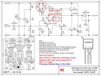
It's close enough for all intents & purposes.This is not the "real" circuit,
It has a capacitor blocking DC destruction from getting to the speaker(s).Don't connect to speakers unless/until these are well tested and burned in.
I use KSA992 in place of the 2N2907, watch the pin outs.
MPSA06 in place of the 2N1711
If you blew the 2n3055s buy a new pair. They will likely have the same hfe if you buy two to four pieces from a source like Digikey.
MPSA06 in place of the 2N1711
If you blew the 2n3055s buy a new pair. They will likely have the same hfe if you buy two to four pieces from a source like Digikey.
VR2 is the weakest link in the schematic considering all things Chinese.
On my builds, I use a 1 Watt Bourns in that position. Very important flaw on those China builds.
I have had amazing results with the offshore JLH1969 boards but I never use their parts.
On my builds, I use a 1 Watt Bourns in that position. Very important flaw on those China builds.
I have had amazing results with the offshore JLH1969 boards but I never use their parts.
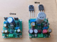
Sure, you board is different but the lessons are the same.
If you are into learning more about the circuit, mods etc, then some of this junk I am throwing at you may be of use.
If you are into learning more about the circuit, mods etc, then some of this junk I am throwing at you may be of use.
It has a capacitor blocking DC destruction from getting to the speaker(s).
That won't block full power HF oscillation.
Thanks for your replies, Stoxx, I appreciate all if the information. I'm afraid I'm a rather pathetic beginner -- I can follow assembly instructions, but my electronics knowledge is minimal.
I'm still trying to figure out how to remove soldered-in items. I've tried various kinds of solder suckers and solder wicks - the process drives me nuts!
I'm still trying to figure out how to remove soldered-in items. I've tried various kinds of solder suckers and solder wicks - the process drives me nuts!
You need a solder pump, it takes a lot of practice and dangerous, you just heat it and place the pump there, after it liquefied you release the trigger, you can dry a joint that way and release the component fairly easy
The click is the trimpot going full range, you reach the point at wich it is fully one side or the other,
Please place a load whenever adjusting anything, it prevents a lot of problems,
My version of the jlh is way advanc3d and can deliver 15 amps in a short then the fuse would blow
I had tube amp destroy 1 watts dummy resistors, better this tan a winding, same, better destroy a resistor than many transistors
- Home
- Amplifiers
- Solid State
- Blew something in a Chinese JLH1969 circuit. How to diagnose problem?