

Finally packaged up "new" ADAU1442 DSP
Posted 2nd September 2012 at 08:11 AM by googlyone
Updated 15th September 2012 at 08:10 AM by googlyone
Updated 15th September 2012 at 08:10 AM by googlyone
Wow - it has taken me months to finally get around to packaging up my latest DSP. With work, travel and holidays I have a huge bag of excuses, but I guess the actual reason is that my old DSP using the Analog Devices AD1940 actually works just fine.
The results are I think pretty neat:
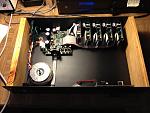
The case was made from leftover bits from the last set I built - the sides are simply timber with a groove routed for the top and bottom panels to sit in, and the front and rear panels screw into the timber sides. It makes a change from the multitude of "all metal" cases that litter my workroom and playroom.
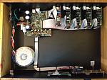
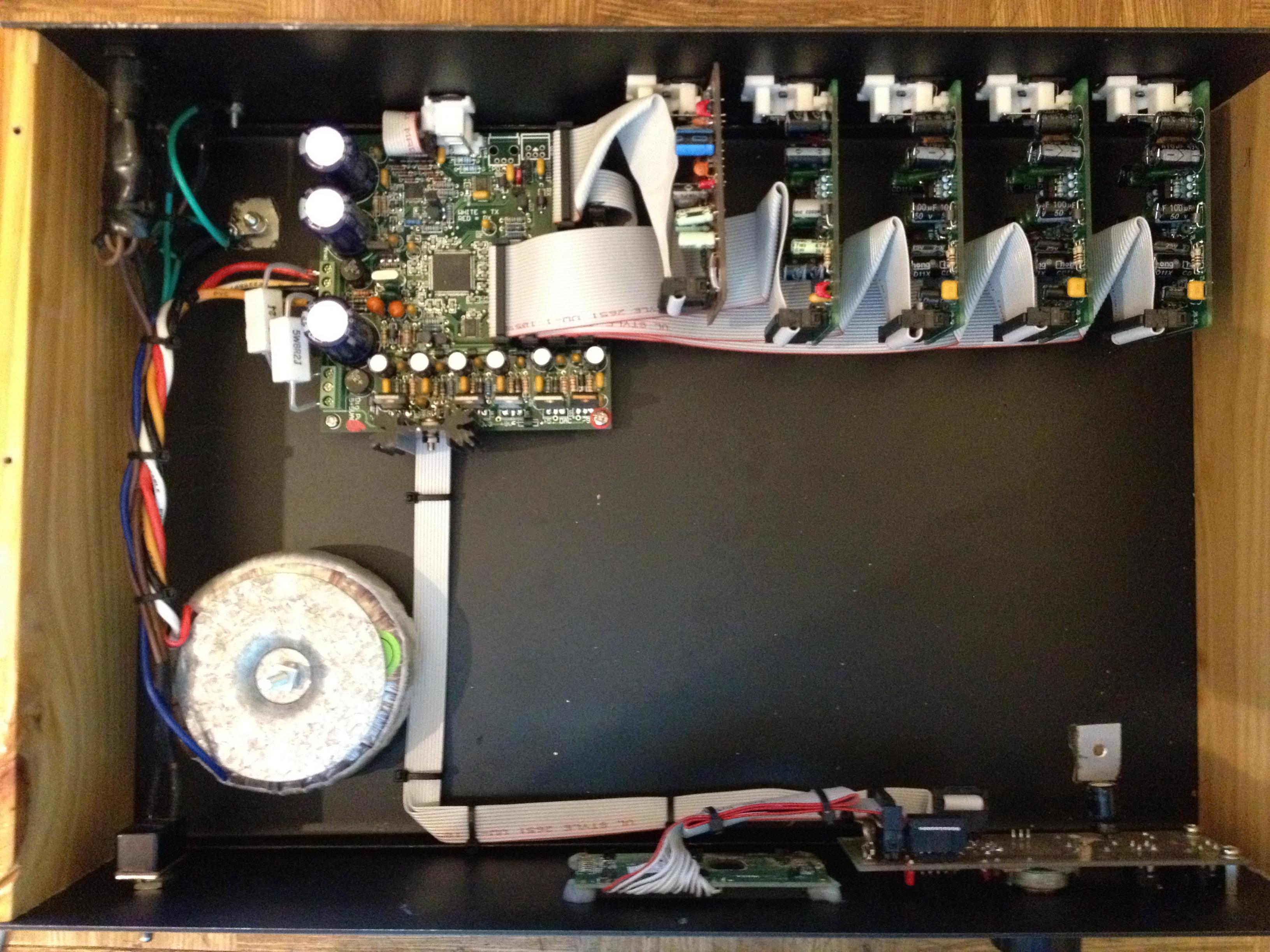
The implementation here has one analogue to digital converter and four digital to analogue converter cards.
These can be seen here:

Where the ADC is the first vertically mounted bard on the left with the slightly scruffy IDC cable. The four DACS follow to the right of that.
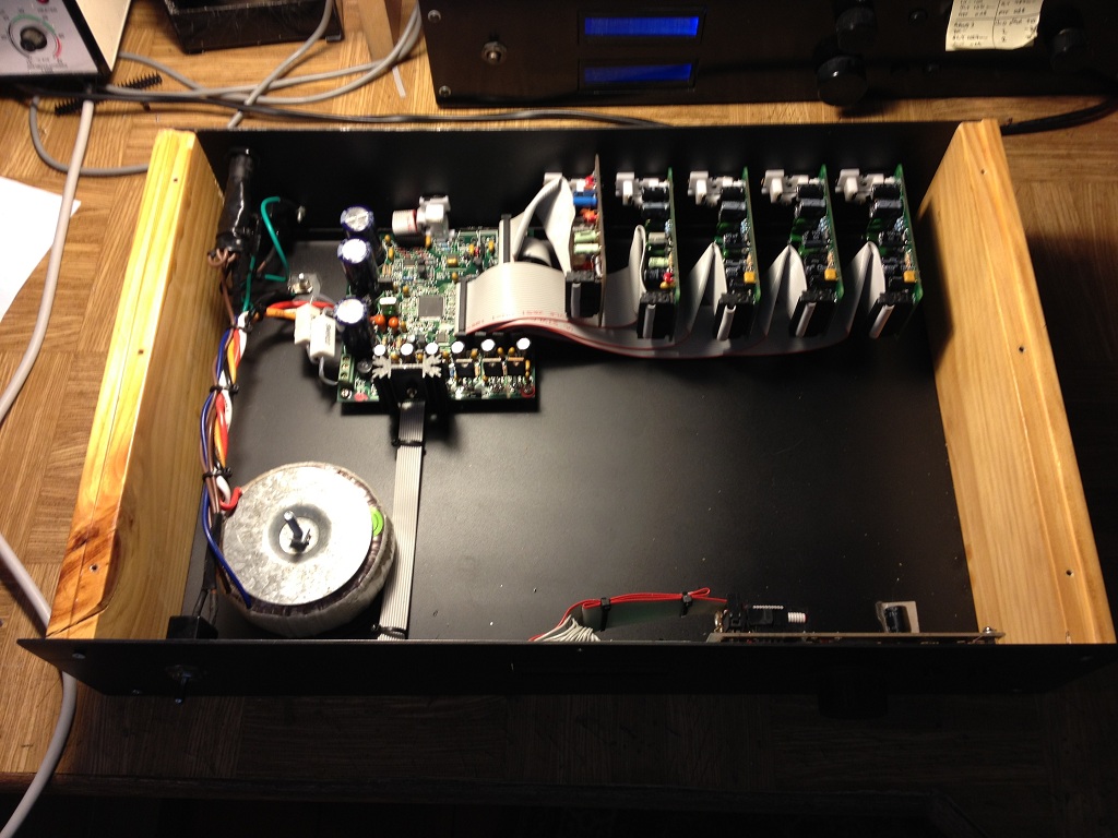
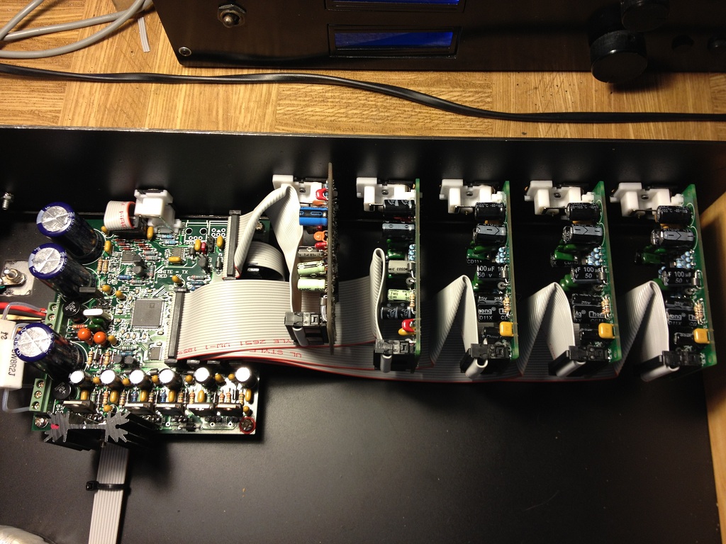
The IDC cable has literally every second conductor earthed. I have done this in the past for moderate speed data, which I consider digital audio to be. The waveform of clock and data on the ADC and DACs is quite clean, so while I included a parallel termination (R-C) for the master clock line on these boards, it is just not necessary.
Those with a keen eye will note the resistors on the left of the DSP board. With this design I included completely seperate power supplies - including transformer inputs - for the analogue and digital sections. In this case I just couldn't be ratted with loading a seperate transformer into the case, so I used just the one.
A consequence of this is that the rather higher than desirable supply voltage for the digital section (The DSP runs off 3.3 volts, and actually regulates this down to 1.8 volts locally) results in some significant dissipation in the regulator.
When I get motivated I will either put another transformer in the case, or wind a separate +/-5Volt winding on the toroid.
All the code for the DSP is stored in the display processor - mounted to the front panel of the case. This is a PIC, though could actually be any micro. Alternatively if you did not want to have the ability to change parameters, you could use a PROM and have the DSP self boot - but this is not how I use this device.
The final tidy ups are now done:
- This circuit was completely floating. This caused some minor susceptibility to hitting the output RCA earths with mains earth. Putting a 100nF Mains rated cap between mains ground and the central earth tidied this up. I played around trying to find where the noise was going, as resetting micro's do not make me happy. After a couple of hours playing with screening of the ribbon cables and under the micro I concluded that I could probably play 'till the cows came home and not identify the exact way the noise was resetting the micro. I did verify there was not a floating input or something silly causing such susceptibility.
The unit tests out nicely - it is a long and tedious process testing (what really amounts to user interface stuff) for so many parameters and so many bands.
I am kind of considering doing a pretty graphics display for this. The only issue I see here is that the really commonly available 128*64 LCD displays have no character generator and will be very expensive on microcontroller memory. I might have a play and see how I go.
The results are I think pretty neat:
The case was made from leftover bits from the last set I built - the sides are simply timber with a groove routed for the top and bottom panels to sit in, and the front and rear panels screw into the timber sides. It makes a change from the multitude of "all metal" cases that litter my workroom and playroom.
The implementation here has one analogue to digital converter and four digital to analogue converter cards.
These can be seen here:
Where the ADC is the first vertically mounted bard on the left with the slightly scruffy IDC cable. The four DACS follow to the right of that.
The IDC cable has literally every second conductor earthed. I have done this in the past for moderate speed data, which I consider digital audio to be. The waveform of clock and data on the ADC and DACs is quite clean, so while I included a parallel termination (R-C) for the master clock line on these boards, it is just not necessary.
Those with a keen eye will note the resistors on the left of the DSP board. With this design I included completely seperate power supplies - including transformer inputs - for the analogue and digital sections. In this case I just couldn't be ratted with loading a seperate transformer into the case, so I used just the one.
A consequence of this is that the rather higher than desirable supply voltage for the digital section (The DSP runs off 3.3 volts, and actually regulates this down to 1.8 volts locally) results in some significant dissipation in the regulator.
When I get motivated I will either put another transformer in the case, or wind a separate +/-5Volt winding on the toroid.
All the code for the DSP is stored in the display processor - mounted to the front panel of the case. This is a PIC, though could actually be any micro. Alternatively if you did not want to have the ability to change parameters, you could use a PROM and have the DSP self boot - but this is not how I use this device.
The final tidy ups are now done:
- This circuit was completely floating. This caused some minor susceptibility to hitting the output RCA earths with mains earth. Putting a 100nF Mains rated cap between mains ground and the central earth tidied this up. I played around trying to find where the noise was going, as resetting micro's do not make me happy. After a couple of hours playing with screening of the ribbon cables and under the micro I concluded that I could probably play 'till the cows came home and not identify the exact way the noise was resetting the micro. I did verify there was not a floating input or something silly causing such susceptibility.
The unit tests out nicely - it is a long and tedious process testing (what really amounts to user interface stuff) for so many parameters and so many bands.
I am kind of considering doing a pretty graphics display for this. The only issue I see here is that the really commonly available 128*64 LCD displays have no character generator and will be very expensive on microcontroller memory. I might have a play and see how I go.
Total Comments 1
Comments
-

 Another very impressive project googlyone!! I'd be rather happy if my projects only took a few months, mine seem to invariably take a few years
Tony.Posted 8th September 2012 at 12:13 PM by wintermute


