Soren,
Can you perhaps post a pinout for the J3 connector? It seems to have pins that route directly to the opto-isolators from the USB input. I.e. if I'm not mistaken this is the I2S output of the USB input? If so, I should be able to hook in the BT > I2S module I have purchased, disabling the USB IC if needed.
I'd appreciate your support on this as currently my 1541 goes unused as I discovered the wonderful world of BT lossless HD streaming with aptX.
Thanks!
An externally hosted image should be here but it was not working when we last tested it.
How do you get lossless audio trough Bluetooth anyway? Aptx is compressed lossy, as far as I know no Bluetooth codec can even do red book audio without cutting frequencies. Are you sure?
I am interested in building with this DAC board. But struggle with what is nice to have and absolutly a must for getting it sound good and 3d.
A good low noice powersupply -+12V for the main voltage. But there is alot of tweeks.....
But what setup will give a damn good DAC. This maybe is done already elswere?
A good low noice powersupply -+12V for the main voltage. But there is alot of tweeks.....
But what setup will give a damn good DAC. This maybe is done already elswere?
+/- 5V for main bus voltage, remove 5v regulators, vref series transistor regulator, added vref capacitance, remove or upgrade lowpass filter cap on raw output, delete muting fets + add relay based mute circuit. In short, get a dam1921/1941 if you are just starting out as its a much higher end platform to begin with that implements some of these already and more importantly adds a much better built-in USB interface that runs the FIFO at a fixed frequency, something the dam1021 cannot do.
+/- 5V for main bus voltage, remove 5v regulators, vref series transistor regulator, added vref capacitance, remove or upgrade lowpass filter cap on raw output, delete muting fets + add relay based mute circuit. In short, get a dam1921/1941 if you are just starting out as its a much higher end platform to begin with that implements some of these already and more importantly adds a much better built-in USB interface that runs the FIFO at a fixed frequency, something the dam1021 cannot do.
Could you please share how to remove the muting circuit? Thanks
I think the DSD FIR1 stop band should start at lower frequencies. There is a quite noticeable bump from the noise shaping artefacts (also noticeable with music in the quieter sections). All my examples are from SACDs ... maybe the situation for other sources may look different.

Could you please share how to remove the muting circuit? Thanks
Remove Q3/Q4 and R392. see: Reference DAC Module - Discrete R-2R Sign Magnitude 24 bit 384 Khz

I am trying to repair a broken DAC board.
I had found the capacitor A is broken.
But I lost the capacitors when I tried to found out what's causing the problems.
Does anyone know the value of these four capacitors(A ,B ,C ,D)?
Seems like your board have taken some beating....
A - C106 - 10u X5R 10V 0603
B - C107 - 1u X5R 25V 0603
C - C15 - 47u X5R 6V3 0805
D - C14 - 4u7 X5R 10V 0603
Actual values are not that critical, T.ex. A and D can be the same....
Seems like your board have taken some beating....
A - C106 - 10u X5R 10V 0603
B - C107 - 1u X5R 25V 0603
C - C15 - 47u X5R 6V3 0805
D - C14 - 4u7 X5R 10V 0603
Actual values are not that critical, T.ex. A and D can be the same....
Thank you for your reply.
U6's out pin is short to ground.
I desoldered ICs and capacitors one by one to find out where causing the promble.
Seems like your board have taken some beating....
A - C106 - 10u X5R 10V 0603
B - C107 - 1u X5R 25V 0603
C - C15 - 47u X5R 6V3 0805
D - C14 - 4u7 X5R 10V 0603
Actual values are not that critical, T.ex. A and D can be the same....

Today, I welded all these parts back.
But after power on, it was found that the part was broken.
This capacitor is short circuited.
After I remove the capacitor, the OPA365 output voltage returns to normal.
Could you tell me the value of this capacitor?
Today, I welded all these parts back.
But after power on, it was found that the part was broken.
This capacitor is short circuited.
After I remove the capacitor, the OPA365 output voltage returns to normal.
Could you tell me the value of this capacitor?
C105 - 10u X5R 10V 0603
Again, not that critical....
Any update on the new batch of boards?
I should receive dam1021 in a couple of days, want to test a few before declaring them in stock.
Good to hear!I should receive dam1021 in a couple of days, want to test a few before declaring them in stock.
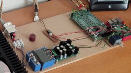
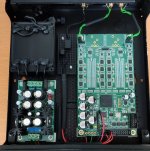
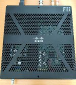
Finally - after sitting on a piece of MFD from day one playing every day - "she" finally got a house of her own.
Søren, if only I had had one of your previous cabinets - unfortunately I hadn't - had to use a second best")
Stay safe.
Søren, if only I had had one of your previous cabinets - unfortunately I hadn't - had to use a second best
Stay safe.
Attachments
- Home
- Vendor's Bazaar
- Reference DAC Module - Discrete R-2R Sign Magnitude 24 bit 384 KHz