.... She usually goes to sleep at 10 and here it is twenty to one and we're still sitting here listening to Bill Evans.......
")
beautiful picture
Well, I have to say, Nice going Rod! These things are really pretty sweet. I've heard lots of different DC fil supplies but was really surprised with the degree of change that your circuit brought to my 10Y line stage. Very impressive.
I'll note here for anyone else trying these boards that it's worth it to try flipping the polarity at the filament connections. When I first put the boards in the sound was very clear but the effect was partially due to a drop in LF content. Flipped, the bass came back and everything is balanced and clean.
Most surprising to me was a drop in the distortion you hear 'between the notes' of jammed piano chords. Having a background in piano, it's one of the weaknesses I notice most in stuff I build and is one of the things that reminds me that I'm not there yet. It seems a bit incredible that an "isolated change to a closed loop circuit" could have such a direct effect on the one it doesn't share current with.Yet even my wife is really digging what this has done. She usually goes to sleep at 10 and here it is twenty to one and we're still sitting here listening to Bill Evans. Way to go Rod. Thanks!
Thanks Ian! Choosing the cathode/GND return (to Filament + or to Filament -ve) is a curious thing. With some amps, there's not much difference, others are like yours, and show a definite preference. For sure - trying it out on both polarities is well worth the trouble.
Both L and R must always be the same way round.
I'm very pleased to hear that it's working well!
It may not be the polarity with respect to the tube, but the change in bias voltage (assuming it hasn't been accounted for) that you hear.
Sheldon
It may not be the polarity with respect to the tube, but the change in bias voltage (assuming it hasn't been accounted for) that you hear.
Sheldon
If the filament's heater supply isn't referenced to ground then is there a change in bias?
I was wondering about the effects of switching the polarity on a used tube. As far as I know, the filament sees a voltage gradient acrossit's length, causing it to emit more one end than the other. I don't know this for sure but if it's true then switching polarity on a tube that's been hooked up one way for a long time might produce an improvement might it not?
The heater supply is not directly referenced to ground. Think of it as a type of battery. In the case of a 10y it's a 7V battery. Connect the negative pole to the cathode resistor, and set the bias at 30V. Now, one end of the filament is at 30V, the other end is 37V. If you reverse the supply, the top of the cathode resistor is still 30V, but the other end of the filament is now at 23V.
If you want to determine if the filament orientation is audible, then keep the cathode resistor connected to the same supply pole and switch the tube pin connections.
If you want to keep the average bias constant, then you need to change the cathode resistor when you switch the supply orientation. Note that this will change the RC circuit formed with your bypass cap. If you are using fixed bias, then you need only change the bias setting so the the average bias is the same for both orientations.
Sheldon
The heater supply is not directly referenced to ground. Think of it as . . . . .
Well Sheldon, I don't like it, but I just tried it again and you appear to be right. It still doesn't make sense to me though. I'll have to play around with a couple of batteries and some resistors to see how it works. Thanks.
Well Sheldon, I don't like it, but I just tried it again and you appear to be right. It still doesn't make sense to me though. I'll have to play around with a couple of batteries and some resistors to see how it works. Thanks.
The output coil of a transformer is isolated from earth. So, if you convert it to DC, it is like a battery in that respect (impedance may not be like a battery, but that just depends on how it's regulated). It has a certain potential from the positive to negative terminals, but it's floating with respect to earth until you connect either side to earth somehow.
Easier to understand if you just draw a few circuit diagrams. To get the full picture, remember that current must always return to its source, so draw the current loops, as well as noting the voltages at various points.
Sheldon
I should add, that my description of conditions with self bias were over simplified to illustrate the point. In real life, the voltage at the cathode resistor will not remain the same for a given resistor value, when the polarity of the supply is switched. The tube will bias up according to the average filament/grid voltage, to find the new equilibrium.
Example: 801 tube at 350V, 20mA, grid to cathode = -25V. With AC filament, the cathode resistor, would be 1.25kOhm
If you use DC, the grid will see approximately the average voltage across the filament. If this is 25V and the filament negative is connected to the cathode resistor, the voltage at this point will be 21.5V or 25V - 7V/2. In order to maintain the 20mA current, the cathode resistor needs to be 1.1 kOhm.
Reverse the supply connections and the cathode resistor sees 25V + 7/2, or 28.5V. To maintain the same operating conditions requires that the cathode resistor be 1.4kOhm.
If the cathode resistor is not changed, the tube will draw more current in the second case than in the first. Point being that the conditions change materially. Sonic changes with changes in operating point are well established. If you prefer one connection over the other, you may be simply picking a preferred operating point - or at least partly so.
Sheldon
Last edited:
. . . . To get the full picture, remember that current must always return to its source, so draw the current loops, as well as noting the voltages at various points. Sheldon
Yes, I do understand that.I was seeing it like a cross with the filament being the horizontal bar - supply nodes connected at each end - and the ground to plate current being the vertical , Rk being below the cross bar and rp above. but that image didn't account for the shared path along the length of the filament. My understanding of it in terms of physics is still pretty vague .
Main thing right now though, the circuit still sounds great. Trying different combinations to sort out what you were talking about I find it sounds best (awesome actually) in this set-up with supply + to the Rk (and Ck) end of the filament.
Thanks Sheldon
A couple of pages or so back, Rod did a nice diagram of the current flow. Main thing is you found a sweet spot. Perfect.
Sheldon
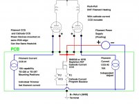
There has been some interest in a Push-Pull version of the DHT Heater PCB. How about this for the solution: A single PCB with 2 Filament CCS, able to work at up to 10A per CCS. TO-220 or TO-247 transistor packages can be used, to deal with filaments from 100mA up to 10A beasts. Each CCS has an independent adjuster. The PP filament regulator has only CCS, no gyrator, since any small amount of ripple current effect would be bucked out by the PP action.
To make the board more useful, a depletion FET CCS is included, for DHT phase splitters - Long Tail Pair with constant current tail. The Supertex DN2540 or any IXYS FETs can be used in the tail circuit. The Depletion FET is in-line with the two CCS transistors, so that 1 heatsink can be used for all three CCS power transistors.
Board is 91mm x 21mm [the SE regulator is 79mm x 21]
Does that look useful to anyone?
Attachments
Thanks John.
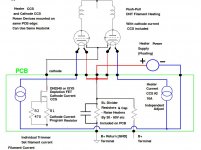
The board is also configurable to work with indirectly heated tubes - which is useful when you are working at low levels or RIAA stages etc. Each heater can be independently adjusted - so you could experiment with fine-tuning the heater voltage in first-stage amplifiers with 6Ж32П (6J32P) or EF86 or 6BS7 etc. These can sometimes be improved in noise (and sound) with the heaters reduced to 5.0V or 5.5V.
The cathode CCS can be used for differential stages, and B+ divider resistors & capacitor positions are provided on the board - so that raising the heaters to +30 or +50V is easy.
Attachments
Rod,
I'm working on a Parallel Push Pull 300B (into a Plitron PAT4006 Toroidal Output Tranny) design right now. I have the 300Bs (ElectroHarmonix), the output Transformers, matching Plitron Toroidal Power Trannies and Plitron 10H Chokes all sitting on the shelf ready to go.
Was about to sit down and nut out the filament supplies and have even ordered in a batch of 50 off 2ST1480FP (since I had to order from the USA it was worth getting 50 so the parts cost was about the same as the shipping). I was thinking of using 8 of your 300B boards for the 2 monoblocks. I want to run the 300Bs fixed biased, using a bias servo, so I would need a sense resistor (say 1 ohm) in the AC return path. That may mean I need separate transformer secondaries and supplies ahead of the filament regulators - as I say, just getting around to thinking about the design.
I was going to tackle the bias servos first - basically the design philosophy would be as per the MJ design (for Class AB) from "Valve Amplifiers" but instead of clipping the current sense signal at 2 times idle (to balance the natural clipping at cut off) I was going to use a MUCH narrower clip window around the idle point, this is (I believe) what Menno and Guido have done in their Tentlabs autobias circuit.
So keep us informed - if you have a suitable push pull filament supply board (to suit the philosophy outlined above), I would certainly be interested in 4 or 5.
Cheers,
Ian
ASIDE: Aussie guys/girls, no Oz stockist for those 2ST1480FP and the shipping cost is prohibitive for small quantities. I only need about 1/2 the 50 I ordered in - give me yell (well a PM) if you need a couple.
Last edited:
Ian, For Parallel PP, with 4x 300B per side [8x 300B for stereo] I would think you would use 2 autobias modules per side [4 for stereo].
If that is right, we would drive those with 2 transformers per side [4x for stereo] and 2 of the PP regulator boards per side [4x for stereo].
We may be able to make it work with only 1 transformer per side if diodes are inserted in the positive feed of the filament supplies. [The positive side of the filaments is returned to GND via independent resistors for Push and Pull]. P-N Diodes should suffice to keep the anode currents separate enough to perform the sensing on 1-ohm sense resistors.
The boards are laid out and ready - will be available with all the components in a kit. I am trying to guess the level of interest in them before getting the PCBs made.
There has been some interest in a Push-Pull version of the DHT Heater PCB. How about this for the solution: A single PCB with 2 Filament CCS, able to work at up to 10A per CCS. TO-220 or TO-247 transistor packages can be used, to deal with filaments from 100mA up to 10A beasts. Each CCS has an independent adjuster. The PP filament regulator has only CCS, no gyrator, since any small amount of ripple current effect would be bucked out by the PP action.
To make the board more useful, a depletion FET CCS is included, for DHT phase splitters - Long Tail Pair with constant current tail. The Supertex DN2540 or any IXYS FETs can be used in the tail circuit. The Depletion FET is in-line with the two CCS transistors, so that 1 heatsink can be used for all three CCS power transistors.
Board is 91mm x 21mm [the SE regulator is 79mm x 21]
Does that look useful to anyone?
It sure does for me as I am running out of space and having everything on one board would, I think, be smaller, in total, than two boards.
Hi Dennis,
The PP board is designed to work with two DHTs running from the same supply - this is normal for PP, but for SE we normally use 2 independent supplies - else the cathodes for Left & Right would be joined.
This PP PCB supports 2x current sink [CCS] only, where the SE PCB supports 1x CCS and 1x gyrator. The gyrator gives a higher level of buffering between the filament and the power supply, and this 2-way buffering is one reason the sound is better than other techniques for DHT heating.
With PP this buffering has less [but not zero] importance, because the PP-action cancels much of the common-mode noise and pollution from the filament supply.
The other application for the PP board is XX-large transmitters like the 304TL - you should be able to support the 12.5A filament current by running half [6,25A] through each CCS on the board - they are independently adjustable.
The GM70 SE solution is tested and validated now. The new v2 PCB has better support for transmitting tubes, with increased weight on the high current tracking, and support for a wider range of power sense resistors. The circuit is not changed. The v2 PCBs are in on November 22.
- Home
- Amplifiers
- Tubes / Valves
- New DHT heater