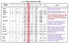
Thanks for that. It's great information. It looks like the one to go for is the 5AU4. It has has the same pin-out, but the filament current is 4.5 Amps. I think I have enough grunt in the power transformer to supply an extra 1.5 Amps. The 5V winding has a DCR of only .062Ω, so there should not be any great voltage drop with 4.5A. They are readily available on the web for about $20. No harm in getting one to try it out.5C3S "near" equivalent is 5U4G (not A or B).
I'm not sure, that this is the most decent driver for 300B.
Single stage 6SN7 has no enough gain -even with CCS load-, thus at higher input level this stage is the limiting factor.
Here is the asc file:
Attachments
Great, many thanks again.Here is the asc file:
Yes, but I'm learning new stuff all the time. In the end we might end up with the best simple 300B SET design of all time. I'm grateful to you for introducing me to the IXCP10M90S, and to euro21 for getting me hooked on LTSpice. I'm learning it very slowly because it's a steep learning curve. Administrator Mooly has done a fine tutorial as a sticky, and is very good at answering all my silly questions. BTW, euro21's simulation of the paralleled 6SN7s is just what I needed. 1.2% distortion at 70 Volts peak drive is very impressive. Soon I will be able to do my own simulations on LTSpice if I can locate some models for the 6SN7.At 130 posts, we are in danger of a moving target (which can never be hit). We could go on forever, but lets settle on a design.
And one more request: could you share the 6SN7 model that you used? Many thanks again.Here is the asc file:
could you share the 6SN7 model that you used?
Download Stephie (formerly Steve) Bench tube libraries:
:: View Forum - Circuits
I'll do that now, thanks.
Final Version, (maybe).
I broke away from the main business of this thread over a week ago to learn LTSpice. I was guided through the process by Moderator Mooly at all times, and I will be eternally grateful to him and all the other members for unceasing help and patience.
I have finally arrived at what I hope will be the final version of the driver section of my 300B SET. I did innumerable simulations with this great application to calculate a cathode resistor value that gave adequate driving voltage with minimum distortion, using the paralleled 6SN7s. I made some very interesting observations along the way, such as: 1) the combining of the two tubes makes no difference to the distortion figure worth talking about - using an idealized CCS model, but the dynamic resistance of the IXCP10M90S is as near as dammit to ideal. 2) the gain of two 6SN7s in parallel configuration was very slightly lower than using one half of the twin triode. 3) the combined plate voltage reduces considerably, but the way things worked out, it was just right for my purposes. 4) 6 mA shared plate current is indeed the sweet spot for minimum distortion with 80 Volts peak output. This was the biggest surprise.
So, it looks like the primary advantage of using 2 6SN7s in parallel is longer tube life, with the plate current shared between the two. All this is based on LTSpice simulations of course, but I will change the common Rk to 1200 Ω from the previous value of 910 Ω, to provide a new grid bias of 7.2 Volts The successful outcome of using the IXCP10M90S in the plate circuit is a worthwhile alternative to an interstage transformer, at least for the 6SN7 (in my view only, of course). With this circuit, an input of 3 Volts RMS is all that is needed to drive most 300B SET output stages to 8 Watts, and this surely is within the capability of most pre-amps
Attachments
Last edited:
I've just done some more Spice simulations, and proved that that statement is incorrect. There is also a 25% reduction in THD with two paralleled tubes.So, it looks like the primary advantage of using 2 6SN7s in parallel is longer tube life, with the plate current shared between the two.
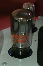
I have just received a nice NOS 5Ц3С in its original box from the Czech Republic. It's working well (so far). From your experience as a Military Developer, can you tell, from the photos, which grade is the tube. I know the bottom line in the square on the top of the box translates as "packer 1". But I can't tell anything else about the tube quality - but maybe you can. Many thanks.OTK sign does not mean, that this is made for military.
It's quality control sign.
"Отдел технического контроля" aka ОТК is mean Technical Control Departments.
This sing only guarantees, that this product fulfils for some technical conditions (tighter tolerance, extended temperature range, schoking etc.).
In the former "socialist" countries (in Hungary too) the QC -even is industry- was not very rigorous, so the parameter variance could be high.
The "worst" (but within tolerance) is "made" for commerce, the "middle" for manufacture, and the top ten percent for military.
Therefore in those factories, that made military product the preliminary QC department was responsible for "good" product purchase.
... if I remember correctly (forty years from now), as former military developer.
p.s. I bought decades ago these tubes for military surplus warehouse.
Attachments
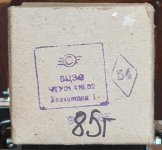
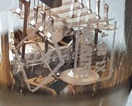
That diamond stamp is a sign of military acceptance. "54" is just the military inspector's personal code.I have just received a nice NOS 5Ц3С in its original box from the Czech Republic. It's working well (so far). From your experience as a Military Developer, can you tell, from the photos, which grade is the tube. I know the bottom line in the square on the top of the box translates as "packer 1". But I can't tell anything else about the tube quality - but maybe you can. Many thanks.
There may be some additional data, but it is always on the bulk box, never on the individual package or the tube itself.
It's good to know that I have a military grade rectifier. Many thanks for the info.That diamond stamp is a sign of military acceptance. "54" is just the military inspector's personal code.
There may be some additional data, but it is always on the bulk box, never on the individual package or the tube itself.
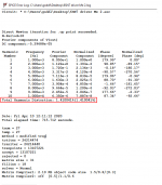
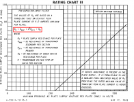
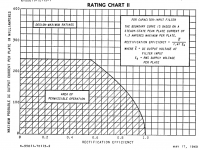
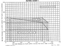
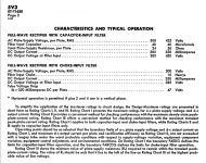
I got a used 5V3 TV rectifier ($8) from the US yesterday, and substituted it for the 5U4G/5Ц3С tubes. I had read the 5V3 spec and rating charts on the General Electric sheet from 1960 and I think (and hope) that I am well within the maximum ratings for this tube. I am determined to keep my HT at about 450 Volts, so I intend to stick with 40μF or thereabouts for the filter capacitance, which is allowed for the 5V3. The RMS voltage feeding each plate is 400V. The formula for resistance feeding the filter cap in relation to the other parameters is given in image 5V4_4. My transformer secondary DCR is 41.4Ω per plate, and for the primary winding is 5.58. The step-up ratio is 400/238 = 1.68. So square this and it becomes 2.82. So, 5.58 appears as 15.74Ω at the secondary. I am using no extra series resistor, so my DCR into each plate of the 5V3 is 15.74 + 41.4 = 57.4Ω. It looks as if I am home and dry - we'll see.I don't think so.
Secondary low DCR (BTW how many Ohms?) AND first capacitor larger that needed is the rectifier killer.
The 5V3 is a brute of a rectifier, capable of supplying way more milliamps than I need, but a slight down-side is that the filament draws 3.8 Amps, as opposed to 3 Amps for the 5U4G/5Ц3С. So, I get a little extra voltage drop from the filament supply winding, which is rated only at 3 Amps. However, I'm still within about 4% of its voltage supply requirement.
Attachments
Last edited:
The formula for resistance feeding the filter cap in relation to the other parameters is given in image 5V4_4.
That should be "feeding each plate".
Final Version.
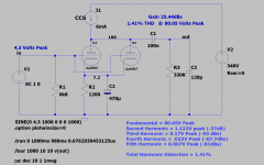
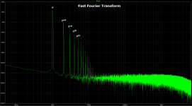
Anyway, in the end I decided on this version of the 300B SET without transformer coupling, instead using a IXCP10M90S CCS as the plate load for the driver tube. I decided to put one in the Cathode/Filament of the 300B also. I built a completely new amplifier, and used the Russian version of the 6J5 (6H8C) as the driver. With only the single driver tube, it takes 2.8 V RMS input for full power.
Using JJ output tubes, I get a full 8 Watts before I see flattening of the waveform, albeit with quite a bit of distortion at full power.
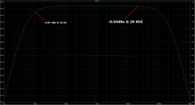
The frequency response is as follows (both channels)?
10 Hz -0.32 dBs
20 KHz -0.5 dBs
30 KHz -1.28 dBs.
Anyway, in the end I decided on this version of the 300B SET without transformer coupling, instead using a IXCP10M90S CCS as the plate load for the driver tube. I decided to put one in the Cathode/Filament of the 300B also. I built a completely new amplifier, and used the Russian version of the 6J5 (6H8C) as the driver. With only the single driver tube, it takes 2.8 V RMS input for full power.
Using JJ output tubes, I get a full 8 Watts before I see flattening of the waveform, albeit with quite a bit of distortion at full power.
The frequency response is as follows (both channels)?
10 Hz -0.32 dBs
20 KHz -0.5 dBs
30 KHz -1.28 dBs.
Attachments
I have been using the Svetlana 5Ц3C with 40μF input filter capacitor for 14 months now with no problems.I don't think so.
Secondary low DCR (BTW how many Ohms?) AND first capacitor larger that needed is the rectifier killer.
Good job.
But I am surprised that neither IXYS current source oscillated.
I use a 100 Ohm gate stopper resistor, some report having to use a 1k gate stopper resistor.
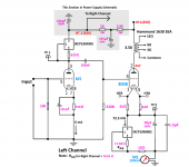
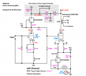
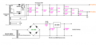
Thanks for the compliment. No problems so far with oscillation. I'm including the complete schematic, with some notes, as well as the PSU schematic for anyone that wants to build it. I have replaced the power transformer with the Hammond 379X. I get about 9½ watts with the increased HT of 475 V.
I think it's a really good design, after trying many similar versions. All thanks to you who introduced me to the IXCP10M90S, for which I am eternally grateful.
Attachments
- Home
- Amplifiers
- Tubes / Valves
- Problem using Hammond 126C IST