yes if max AC plate supply voltage 2X500V and low impedance 4uF max
and swing choke and snubber resistor then filter choke
and you get the real valve sound,
and swing choke and snubber resistor then filter choke
and you get the real valve sound,
If I drop the filter input capacitance from 110μF to 40μF, what drop in HT voltage will there be? It's 450 Volts now.yes if max AC plate supply voltage 2X500V and low impedance 4uF max
and swing choke and snubber resistor then filter choke
and you get the real valve sound,
There is a choke.i c'ant said, no choke in your psu
one wire resistor minimum in serie 22 ohm before caps
I have a question, the answer to which may be obvious to some folks, but I need to be sure.
If I change the secondary of the power transformer from 400-0-400 to 425-0-425, will the HT1 voltage rise by the same ratio (425/400) to 478.125 Volts, everything else being equal? It's 450 Volts now.
If I change the secondary of the power transformer from 400-0-400 to 425-0-425, will the HT1 voltage rise by the same ratio (425/400) to 478.125 Volts, everything else being equal? It's 450 Volts now.
Attachments
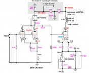
I trawled this forum and many others to try and get opinions on what to do with the unused section of the double triode 6SN7. There are so many differing opinions out there, from "cathode poisoning" to remarks about a vintage Fender amp leaving a triode section just floating with no harm done over a long number of years, that I decided to parallel the two sections and see what happens. This is not as simple as it might seem when using a CCS as a plate load. The total combined plate current in my case will always be 6mA, so 3mA per section. The bias will always be 5.5 Volts because it is set by the common Rk. So what can change? Well, the voltage drop across the combination changed to 145 Volts instead of 180 Volts on the single section previously - because of lower rp. There is lots of voltage swing available to drive the 300B (70 Volts RMS). The CCS heat-sink gets a little hotter because it is dropping a larger share of PSU voltage - 195 Volts as opposed to 160 Volts.
I get the advantage of lower output impedance, higher gain (although I don't really need it) and 3 dBs less stage noise, and of course longer tube life. I have been listening all afternoon, and can hear a substantial difference in tone, although this could be my imagination, as often happens when doing listening tests.
I get the advantage of lower output impedance, higher gain (although I don't really need it) and 3 dBs less stage noise, and of course longer tube life. I have been listening all afternoon, and can hear a substantial difference in tone, although this could be my imagination, as often happens when doing listening tests.
Attachments
Last edited:
goddlediddles,
You paralleled the 6SN7.
Do you want to check the balance of the 2 triode sections?
Change each cathode circuit to individual self bias resistors, 1820 Ohms each.
Use individual bypass caps across each 1820 Ohm resistor.
Measure the voltage across each 1820 Ohm resistor.
That way you can see how well the two triode halves are balanced.
Just something you may want to try.
goddlediddles,
Oh. By the way, before I forget, your amplifier looks absolutely beautiful!
I always use a single handle on my amplifiers, and some of them have analog meters too.
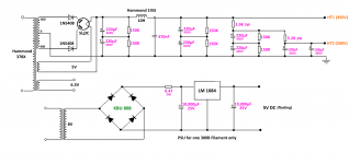
claudiomas was talking about a choke input filter B+ supply (post # 101).
All other things being equal, the maximum B+ voltage versus the secondary RMS voltage
(in your case, 400Vrms center tap to one end):
Capacitor input filter: 400Vrms x 1.414 = 566VDC minus (-) the Rectifier Voltage drop.
In addition, any 1/2-secondary DCR and any series resistors in the B+ will cause additional voltage drops.
Choke input filter: 400Vrms x 0.9 = 360VDC minus (-) the Rectifier Voltage drop.
In addition, any 1/2-secondary DCR and any series resistors in the B+ will cause additional voltage drops.
The voltage drop of a rectifier tube is Larger for a Capacitor input filter, than it is for a Choke input filter, when the load currents are equal.
So you get back a little of the voltage drop of the Choke input filter.
You have to use a larger secondary voltage for a Choke input filter to get the same voltage as a Capacitor input filter . . .
. . . so why use a choke input filter?
Well, a choke input filter does the following:
Causes the power transformer to run cooler
Causes the rectifier tube to run cooler
Choke input filter causes the B+ ground loop to be "quieter" (noisy ground loops with lots of upper harmonics, such as those that are created with Capacitor input filters, tend to get into the amplifier output. And noisy ground loops upper harmonics are more disturbing to the ear and brain, they are more audible).
Yes, there are disadvantages to a Choke input filter:
Good chokes are more expensive than a capacitor
Choke input filters require higher power transformer secondary voltage
Chokes take up more space
Chokes create interfering magnetic fields, require spacing from output transformers, and
require non magnetic chassis, like aluminum.
Choke angular rotation versus output transformer rotation is important.
Push pull output transformers are less sensitive than single ended air gap output transformers.
Whenever I have enough power transformer secondary voltage, I use Choke input filters.
Oh. By the way, before I forget, your amplifier looks absolutely beautiful!
I always use a single handle on my amplifiers, and some of them have analog meters too.
claudiomas was talking about a choke input filter B+ supply (post # 101).
All other things being equal, the maximum B+ voltage versus the secondary RMS voltage
(in your case, 400Vrms center tap to one end):
Capacitor input filter: 400Vrms x 1.414 = 566VDC minus (-) the Rectifier Voltage drop.
In addition, any 1/2-secondary DCR and any series resistors in the B+ will cause additional voltage drops.
Choke input filter: 400Vrms x 0.9 = 360VDC minus (-) the Rectifier Voltage drop.
In addition, any 1/2-secondary DCR and any series resistors in the B+ will cause additional voltage drops.
The voltage drop of a rectifier tube is Larger for a Capacitor input filter, than it is for a Choke input filter, when the load currents are equal.
So you get back a little of the voltage drop of the Choke input filter.
You have to use a larger secondary voltage for a Choke input filter to get the same voltage as a Capacitor input filter . . .
. . . so why use a choke input filter?
Well, a choke input filter does the following:
Causes the power transformer to run cooler
Causes the rectifier tube to run cooler
Choke input filter causes the B+ ground loop to be "quieter" (noisy ground loops with lots of upper harmonics, such as those that are created with Capacitor input filters, tend to get into the amplifier output. And noisy ground loops upper harmonics are more disturbing to the ear and brain, they are more audible).
Yes, there are disadvantages to a Choke input filter:
Good chokes are more expensive than a capacitor
Choke input filters require higher power transformer secondary voltage
Chokes take up more space
Chokes create interfering magnetic fields, require spacing from output transformers, and
require non magnetic chassis, like aluminum.
Choke angular rotation versus output transformer rotation is important.
Push pull output transformers are less sensitive than single ended air gap output transformers.
Whenever I have enough power transformer secondary voltage, I use Choke input filters.
Last edited:
6A3sUMMER, thanks for the compliment. And thanks also for all the advice and information - I found it really useful. I will stick with the capacitor input filter on the PSU. Therefore I won't need to order a higher voltage power transformer. The one modification I carried out, on the advice of a number of members, was to reduce the input capacitance in the PSU filter to below 47μF. I changed it to 44μF (220μF in series with 56μF). The good old Soviet military 5Ц3C is tough but maybe not that tough.goddlediddles,
Oh. By the way, before I forget, your amplifier looks absolutely beautiful!
I have also put in a third set of chassis-mounted test-points to monitor the voltage on the combined plates of the 6SN7s. That way, if it changes substantially, I will know if something is wrong with one or other of the twin-triode sections. BTW, I discovered a matched pair of Russian 6SN7 equivalents (6H8C) on eBay for $10. They sound really great in my single stage driver section. They do not suffer from microphonics, which is a common complaint about Russian tubes. I'm settling in for another day's listening now (Covid-19 precautionary isolation), so everything being OK, I'll close it up and declare job done at last.
Last edited:
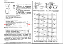
The data sheet doesn't say "maximum". In the section ""Nominal Electrical Data" it states "(Емкос фильтра МКф - 4)".The 5C3S first capacitor's maximum value only 4uF!
Attachments
Use 6J5s 😉I trawled this forum and many others to try and get opinions on what to do with the unused section of the double triode 6SN7.
Sure. A nice octal tube in a metal case. I thought of that. NOS are plentiful on eBay. The problem for me would be the pin-outs onto the printed circuit board. Paralleling the two sections of the 6SN7 has brought a number of pluses, so I'll leave it that way. Thanks.Use 6J5s 😉
Sooner or later they all start arcing, if you use these horrible values.The data sheet doesn't say "maximum".
I've been using them for decades.
Well, arcing can only occur when there is no longer a high vacuum. So what replaces it - gas or vaporized metal? Anyway, I have used this one for a year, with very many on-off cycles, running it into 110μF with no problems. Bringing the capacitance down to 44μF makes me sleep a little easier at night.Sooner or later they all start arcing, if you use these horrible values.
I've been using them for decades.
Well, arcing can only occur when there is no longer a high vacuum.
I don't think so.
Secondary low DCR (BTW how many Ohms?) AND first capacitor larger that needed is the rectifier killer.
Did you use the OTK military version of the 5Ц3С? Some say they are bullet-proof.I don't think so.
Secondary low DCR (BTW how many Ohms?) AND first capacitor larger that needed is the rectifier killer.
6A3sUMMER.goddlediddles,
You paralleled the 6SN7.
Do you want to check the balance of the 2 triode sections?
Change each cathode circuit to individual self bias resistors, 1820 Ohms each.
Use individual bypass caps across each 1820 Ohm resistor.
Measure the voltage across each 1820 Ohm resistor.
That way you can see how well the two triode halves are balanced.
Just something you may want to try.
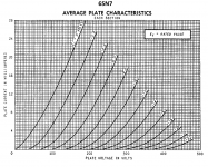
I have been trying to figure out how to combine the 6SN7 Ia-Va curves on the data sheet and draw a load-line for the parallel combination. I just can't see a way to do it.
Attachments
Did you use the OTK military version of the 5Ц3С? Some say they are bullet-proof.
OTK sign does not mean, that this is made for military.
It's quality control sign.
"Отдел технического контроля" aka ОТК is mean Technical Control Departments.
This sing only guarantees, that this product fulfils for some technical conditions (tighter tolerance, extended temperature range, schoking etc.).
In the former "socialist" countries (in Hungary too) the QC -even is industry- was not very rigorous, so the parameter variance could be high.
The "worst" (but within tolerance) is "made" for commerce, the "middle" for manufacture, and the top ten percent for military.
Therefore in those factories, that made military product the preliminary QC department was responsible for "good" product purchase.
... if I remember correctly (forty years from now), as former military developer.
p.s. I bought decades ago these tubes for military surplus warehouse.
Last edited:
Thanks for that. It is excellent information. Great to have someone from a former Warsaw Pact country to supply that kind of detail.OTK sign does not mean, that this is made for military.
It's quality control sign.
"Отдел технического контроля" aka ОТК is mean Technical Control Departments.
This sing only guarantees, that this product fulfils for some technical conditions (tighter tolerance, extended temperature range, schoking etc.).
In the former "socialist" countries (in Hungary too) the QC -even is industry- was not very rigorous, so the parameter variance could be high.
The "worst" (but within tolerance) is "made" for commerce, the "middle" for manufacture, and the top ten percent for military.
Therefore in those factories, that made military product the preliminary QC department was responsible for "good" product purchase.
... if I remember correctly (forty years from now), as former military developer.
- Home
- Amplifiers
- Tubes / Valves
- Problem using Hammond 126C IST