I have managed to translate some of the unclear Russian typed characteristics on the 5Ц3С data sheet. Under the section which reads "Nominal Electrical Data" It states that the filter capacitance is 4μF (Емкос фильтра МКф - 4) So where does that leave us/me?
Hi Godfrey, Working in PSUDII with a C input filter a few days ago, I encountered a warning message about IFRM being exceeded for the rectifier I was using, a 5U4G. With a Google search, I came upon: IFRM: Between the Rectifier and Capacitor - Jimmy's Junkyard which explains that for a C input filter, too large an input C will result in an excessive charging current for the input C that could cause arcing/damage to the rectifier. Jimmy suggests that anything >30uF is too big and actually recommends starting with an input C of 4-10 uF. Turns out that the 5U4-GB has a higher IFRM (1.0A) than the 5U4G (0.8A), so I changed to that and went on my merry way in PSUDII. Have you found an IFRM spec in the 5U3C datasheet?
I have been using the Russian version of the 5U4G for quite some time now, and have not got a problem so far. Have a look at post 155 and do the maths.
Last edited:
I have been using the Russian version of the 5U4G for quite some time now, and have not got a problem so far. Have a look at post 155 and do the maths. I've used the TV rectifier, 5V3 successfully, but with a lower HT winding voltage 400 - 0 - 400.
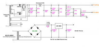
Hybrid Full Wave, Not Bridge, Rectifier
Hi Godfrey,
I've seen hybrid full wave *bridge* rectifiers, but never have seen one like yours. Please help me to understand what you are trying to accomplish with the 1N5408s in the power transformer secondary feeds to the rectifier valve...the two diodes in series? ? ? It's not in Morgan Jones, neither any place else I can find.
Thanks and Best,
Robert
They are there to protect the tube rectifier on reverse voltage. They are a feature of many other designs as well.
Building the Amp.
For anyone contemplating building the amp, I would suggest starting with the lower voltage power transformer, Hammond 378X (400 - 0 - 400). It's a bit less risky, unless you are confident of what you are doing. The 379X is an experiment that seems to have worked out OK.
For anyone contemplating building the amp, I would suggest starting with the lower voltage power transformer, Hammond 378X (400 - 0 - 400). It's a bit less risky, unless you are confident of what you are doing. The 379X is an experiment that seems to have worked out OK.
Internal wiring.
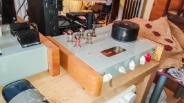
Some folks baulk at the idea of using connection blocks in the wiring. It was another experiment that has given no trouble so far. They are not the ordinary electrical connection blocks that can be bought at the hardware store. They were more expensive, and have a flat plate below the screw, so as not to crush the wires, and to ensure a good connection to all wires and components.
Link to photos.
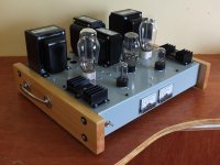
That looks great!
And I like the wood sides, and the handle on the side.
My amplifiers each have a handle on them.
I also have an analog meter on them when possible.
Keep up the good work.
And I like the wood sides, and the handle on the side.
My amplifiers each have a handle on them.
I also have an analog meter on them when possible.
Keep up the good work.
That looks great!
And I like the wood sides, and the handle on the side.
My amplifiers each have a handle on them.
I also have an analog meter on them when possible.
Keep up the good work.
Thanks for the compliment. Could you post a photo of one of your amps - the one that you like best/
goddlediddles,
I admit, I never built a good looking amplifier.
All of my amplifiers are ugly.
I start with an old amplifier that had missing parts, and then I use the old chassis and original power transformers. No other parts are from the original amplifier.
And, I try lots of different configurations on that chassis, so there are lots of extra holes, etc.
Here is an example of one of my amplifiers. You can see the meter on the front, and the handle on the back.
A Simple Low Power 7591 Push Pull Amplifier
Perhaps I will take some photos of other amplifiers later, and post them.
Hi Godfrey,
Could you please indicate what sort of connexions you are using them for?
Best,
RC
More than half of them. You will need to look at them in the photos, which there is a link for.
My 300B Construction - Google Drive
Last edited:
Hi Godfrey,
Could you please indicate what sort of connexions you are using them for?
Best,
RC
I decided as I went along. I had no plan for the connexions, but I made sure to use as many terminal points as possible, thereby providing maximum flexibility. If I were building the same amp again, I would use tag strips and solder. As I said earlier, it was an experiment that seems to have worked out OK. "Eyeball Engineering" is what I remember a friend of mine from the US calling it. Leave plenty of room by using a large chassis. Mine is 17 X 14 X 3 inches. It's a Hammond part with the part number 1441-38. The matching bottom panel is part number 1431-38.
Last edited:
Note about the schematic in Post # 160
The 100mA meter sees all the instantaneous signal current of the 300B.
The meter sees both the AC and DC current.
If you connect the meter in series with the IXYS current source, then the Bypass Cap will take all of the instantaneous signal current of the 300B.
The meter will only see DC current.
Yes, but at the beginning, I needed to see the initial current surge through the 300B at power-on, caused by the bypass capacitor. With 100μF, it was over 100mA, which I didn't like, so I reduced it to 50μF, and the surge was negligible. Bass response did not suffer much. I decided to leave the meter where it was, in case of future modifications.
The IXCP10M90S makes thinks a little complicated.
I'm not too sure about the logic of my argument, but I think I'm right (think).
Last edited:
- Home
- Amplifiers
- Tubes / Valves
- Problem using Hammond 126C IST