Member
Joined 2009
Paid Member
Those SiC diodes aren't inexpensive, do they make that much of a difference over the alternatives ?
I became so enthusiastic about the IXCP10M90S, … interesting experiments lie ahead.
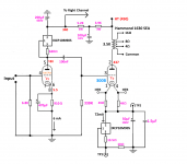
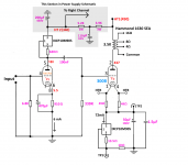
I have a question — The IXCP10M90S serving as the anode-load for the 6SN7 on the left-hand side of the diagram is effectively serving as a 26.6 kΩ resistor, with of course it also acting as a much higher impedance virtual A/C load (in the low MΩ?) due to its current-regulating capacity…
That's not in question.
To me, what is, is the value of the 620 Ω resistor chosen as the IXCP10M90S constant-current setpoint. I would think that its value is quite sensitive to the particular health-and-manufacturing-standards of the 6SN7 sitting in the socket.
I say this because the 180 V anode quiescent point is sensitive to the transconductance of the valve, the inversion of gm to RP and of course, the particular actual current that all those combined passes thru the 910 Ω 'cathode bias' resistor.
Y'know what I mean?
⋅-⋅-⋅ Just asking, ⋅-⋅-⋅
⋅-=≡ GoatGuy ✓ ≡=-⋅
Take a look at Bartola Valves website - Ale Moglia. Read up on using his gyrator with a 6×10⁵P or 6×10⁶P as driver for your 300b. And also look at using a SIC diode combination in the cathode. I'm using his suggestion of the C3D02060F and it sounds great. You'll get around .85v per diode.
OK, I might not be the brightest bulb in the socket, but it seems to me using a chain of these silicon carbide Schottky diodes at their 850 mV VF point isn't particularly close to an ideal VBIAS constant voltage source.
But... Dâhmned convenient, I'll give y'all that. But there looks to be quite a bit of wobble in VF with both current and operating temperature. Especially down near 850 mV.
So, a chain of the things will definitely have an additive compounding effect as well. If the 850 mVF wiggles by ±20% with signal conduction peaks and valleys, and it varies by maybe as much with cold-to-warm temperature, I would think that the overall chain would also vary by the same amount.
⋅-⋅-⋅ Just asking, ⋅-⋅-⋅
⋅-=≡ GoatGuy ✓ ≡=-⋅
Those SiC diodes aren't inexpensive, do they make that much of a difference over the alternatives ?
Seems — to me — that there are 2 different applications for them. One might be to act as a low-voltage stack for the 6SN7 stage, as an alternative to the capacitor-bypassed cathode resistor.
They wouldn't be terribly expensive.
Still … because the 5.5 volts would require 5.5 V ÷ 0.850 VF = 6 or 7 of them, then the effective DC virtual resistance is about 180 to 190 Ω apiece. 920 for the stack.
Given the VF wobble synchronous with signal, I still think it concomitant to cap-bypass the diode stack, to give an A/C impedance much closer to ZERO Ω. Say
Z = 1/(2πFC) …
C = 1,000,000 ÷ 2πFZ (in µF)
F = 20 Hz
Z = ⅓ of 900 Ω = 300 Ω
C = 159,155 / (20 × 300)
C = 26.6 µF … or in common parts
C = 33 µF
OK, that's one case.C = 1,000,000 ÷ 2πFZ (in µF)
F = 20 Hz
Z = ⅓ of 900 Ω = 300 Ω
C = 159,155 / (20 × 300)
C = 26.6 µF … or in common parts
C = 33 µF
If 'the other case' is to act as a near-constant voltage source for a 300B output final, running at some 72 mA and requiring a bias of ±75 V as well, then I don't think using silicon carbide diodes is economically tenable. You'd need quite a pile. Like … 70+.
⋅-⋅-⋅ Just saying, ⋅-⋅-⋅
⋅-=≡ GoatGuy ✓ ≡=-⋅
What may be more important with these SIC diodes is they appear to sound good. Ale and I and a friend spent hours with a preamp shootout (on his site) comparing different topologies with the same musical excerpts. All three of us agreed that the SIC diode topology sounded best, comparisons being largely filament bias if I recall.
However, while I get good results with the driver stage using SIC diodes, benefits being mainly clarity and detail, I found that using it for both driver and output stages gave a bright and rather edgy response. So for my 4P1Ls in PSE I went back to filament bias, which was smoother.
Yes, these SIC diodes are not so cheap, but they are affordable. Do they make a difference? in my 26 stage, yes, they are the bias of choice replacing filament bias. Results may vary with other tubes. The 26 is warm and smooth and seems to tolerate SIC bias quite well. I think SIC diodes need to be tried on a tube-to-tube basis to see if they are the best option.
I only use DHTs so for me filament bias is always the alternative of choice. With indirectly heated tubes, suck it and see. In any case I ditched cathode resistors with cathode bypass caps as one of the worst choices and one I abandoned a while ago.
I've just arrived back home from Berlin, so I'll read all the updates tomorrow and try to give answers and further opinions. Great selection of audio components there at Banzai Music (Link)
Yes, I can see exactly what you are getting at. All I can say in reply is that I will report here on any changes that I notice as the tube ages or is changed. I need to arm myself with a standby pair for backups, and I will choose from the cheapest unmatched ones on the market, and after popping one in, I'll measure everything again.I have a question — The IXCP10M90S serving as the anode-load for the 6SN7 on the left-hand side of the diagram is effectively serving as a 26.6 kΩ resistor, with of course it also acting as a much higher impedance virtual A/C load (in the low MΩ?) due to its current-regulating capacity…
That's not in question.
To me, what is, is the value of the 620 Ω resistor chosen as the IXCP10M90S constant-current setpoint. I would think that its value is quite sensitive to the particular health-and-manufacturing-standards of the 6SN7 sitting in the socket.
I say this because the 180 V anode quiescent point is sensitive to the transconductance of the valve, the inversion of gm to RP and of course, the particular actual current that all those combined passes thru the 910 Ω 'cathode bias' resistor.
Y'know what I mean?
⋅-⋅-⋅ Just asking, ⋅-⋅-⋅
⋅-=≡ GoatGuy ✓ ≡=-⋅
On reflection though, surely the 620Ω setting resistor is within a closed loop, and can only cause a change in the 6SN7 plate current if its value changes due to temperature fluctuations. The current through the IXCP10M90S changes very little with temperature fluctuations. The ambient within the chassis does not change that much, and the IXCP10M90S is always at about 50º C. So the current through the tube will always be close to 6mA; therefore the bias will always be at about 5.5 Volts. the Voltage at the plate will vary when the tube ages or is changed. What do you think?To me, what is, is the value of the 620 Ω resistor chosen as the IXCP10M90S constant-current setpoint. I would think that its value is quite sensitive to the particular health-and-manufacturing-standards of the 6SN7 sitting in the socket.
On reflection though, surely the 620Ω setting resistor is within a closed loop, and can only cause a change in the 6SN7 plate current if its value changes due to temperature fluctuations. The current through the IXCP10M90S changes very little with temperature fluctuations. The ambient within the chassis does not change that much, and the IXCP10M90S is always at about 50º C. So the current through the tube will always be close to 6mA; therefore the bias will always be at about 5.5 Volts. the Voltage at the plate will vary when the tube ages or is changed. What do you think?
Yah, I guess that would be the logic. I still wonder tho'. Perhaps the voltage-dependent transconductance of the amplifying valve is the negative slope compensation that makes it all balance out. ⋅-=≡ GoatGuy ✓ ≡=-⋅
OK, a 50μF cap across the IXCP10M90S has solved the problem.A WARNING
I have discovered a serious problem with the implementation of the IXCP10M90S in the cathode circuit of the 300B. On power-up, the current through the tube shoots up to 110mA, and then drops back to its regulation 72mA after about 1.5 seconds. I have traced the cause of this to the the time it takes to charge the 470μF cathode bypass capacitor. The resistance of the CCS drops down very low just after power-on, as the filament comes up to temperature, to do its job of maintaining the Ia at 72mA, thereby robbing the bypass cap of the ability to charge. The voltage across the combination drops, and therefore the grid bias. 470μF is way to large, so I will substitute a 47μF cap. This still gives me a low break-point of about 3.5Hz, and the gain should drop by about only 0.7dBs at 40Hz. I don't know why I put such a large bypass cap there in the first place, but reducing it by a factor of 10:1 should solve the problem.
The frequency response is flat down to 20Hz and 0.5 dBs down at 20 KHz, and it will produce 7.5 Watts before clipping or rounding of the sine-wave. I'm finished with this project now, so I've put in a pair of brand new JJs, and it will be some time before I can evaluate the overall result, but it sounds fine right now, if not a little harsh in the upper mid-band - time will tell.
Attachments

Last edited:
A MYSTERYOK, a 50μF cap across the IXCP10M90S has solved the problem.
I have just done another frequency response measurement, and discovered that this topology has a low frequency response almost flat down to 10 Hz. How can this be? The reactance of the 50μF bypass capacitor in the final stage at 10 Hz is 318 Ohms. Is it because the cap is bypassing an effective 30 or 40K audio resistance in reality, instead of the perceived resistance of about 1.1K, which is the DC effective resistance of the CCS with this setup? Or is it some kind of NFB compensatory effect? I knew there was something strange when in the course of investigating the effect of various values of bypass cap, it sounded not too bad with only the 1.5μF HF bypass cap in circuit.
Attachments
Last edited:
The function of a bypass cap is to bypass signal, not DC quiescent current.
You are bypassing the impedance of the 300B triode filament (filament "as" a cathode, not the filament resistance) that is in series with RL / (u + 1).
300B: Gm = 5500 Micromhos.
300B: u = 3.85
1/Gm = 812 Ohms, the "cathode" impedance of the 300B with the plate load a short circuit (0 Ohms to B+) But we have to account for the plate that is loaded by the output transformer, so . . .
The plate load, RL is 3500 Ohms. We need to divide RL by (u +1); u + 1 = 4.85.
3500 / 4.85 = 722 Ohms
812 Ohms + 722 Ohms = 1534 Ohms
As you stated, the reactance at 10 Hz of 50 uF is 318 Ohms.
You have 328 Ohms bypassing 1534 Ohms.
The high impedance of the current source (AC; not "effective DC resistance of V/current) is much much higher than 1534 Ohms, so it falls out of the frequency response equation for that circuit.
Last edited:
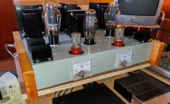
Project Completion.
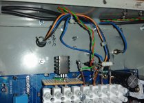
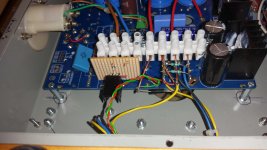
I've been working on my 300B SET since last April. I've been through 10 different iterations, and am now finally happy with the performance and sound of the end result. The IXCP10M90S in the plate circuit of the 6SN7 was the breakthrough that allowed me the capability of driving the grid of the 300B to 70 Volts RMS, with good linearity, if needed (lots to spare). Many thanks to 6A3sUMMER for that excellent suggestion and GoatGuy for working out the dynamic resistance for me. (diyAudio is just great). I dispensed with the first half of the 6SN7 because I have way more than enough output from my small Behringer mixer to drive the amp.
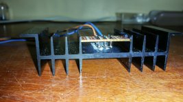
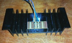
I decided to try the IXCP10M90S in the cathode/filament circuit of the 300B, and was delighted with the result. It gave me a certain amount of confidence that using an Rg of 330K, it would not run away, even at high power levels, and so it has turned out. I have used unmatched Liuzhous and Golden Dragons with no problems so far. The plate current is always 72 mA but of course the bias changes on each and every tube, meaning I will need to drive left and right asymmetrically for full power. The temperature as measured at the closest point to the CCS never goes above 46ºC, and that's with 21K/Watt heatsinks.
The frequency response is -2 dBs at 10 Hz, and -0.6 dBs at 20KHz, with no wiggles in the curve. The -3 dB point at the top end is 35 KHz. I can drive both left and right to 7.7 Watts, albeit with a large amount of distortion, but nice and clean at 5 Watts. The total hum and noise is 0.75 mV RMS at the speaker terminals into 8Ω.
I've been working on my 300B SET since last April. I've been through 10 different iterations, and am now finally happy with the performance and sound of the end result. The IXCP10M90S in the plate circuit of the 6SN7 was the breakthrough that allowed me the capability of driving the grid of the 300B to 70 Volts RMS, with good linearity, if needed (lots to spare). Many thanks to 6A3sUMMER for that excellent suggestion and GoatGuy for working out the dynamic resistance for me. (diyAudio is just great). I dispensed with the first half of the 6SN7 because I have way more than enough output from my small Behringer mixer to drive the amp.
I decided to try the IXCP10M90S in the cathode/filament circuit of the 300B, and was delighted with the result. It gave me a certain amount of confidence that using an Rg of 330K, it would not run away, even at high power levels, and so it has turned out. I have used unmatched Liuzhous and Golden Dragons with no problems so far. The plate current is always 72 mA but of course the bias changes on each and every tube, meaning I will need to drive left and right asymmetrically for full power. The temperature as measured at the closest point to the CCS never goes above 46ºC, and that's with 21K/Watt heatsinks.
The frequency response is -2 dBs at 10 Hz, and -0.6 dBs at 20KHz, with no wiggles in the curve. The -3 dB point at the top end is 35 KHz. I can drive both left and right to 7.7 Watts, albeit with a large amount of distortion, but nice and clean at 5 Watts. The total hum and noise is 0.75 mV RMS at the speaker terminals into 8Ω.
Attachments
I've been working on my 300B SET since last April. I've been through 10 different iterations, and am now finally happy with the performance and sound of the end result. … and GoatGuy for working out the dynamic resistance for me … the amp is… nice and clean at 5 Watts. The total hum and noise is 0.75 mV RMS at the speaker terminals into 8Ω.
you are definitely welcome. DIYAudio is definitely one of the Internet's unique resources. or, “any time” so long as we're alive and kicking! ⋅-=≡ GoatGuy ✓ ≡=-⋅
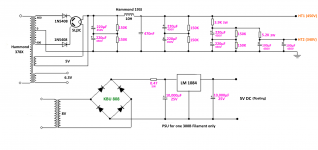
What is that tube rectifier type, 5U3C?
Is the first capacitance of 110uF a little too much for it?
What is the 5U3C's max cap rating?
What is the DCR of the B+ secondary?
If high enough, it might help, or a series resistor.
Is the first capacitance of 110uF a little too much for it?
What is the 5U3C's max cap rating?
What is the DCR of the B+ secondary?
If high enough, it might help, or a series resistor.
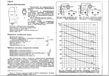
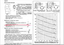
The 5ц3с rectifier is a Russian (Svetlana) military version of the 5U4G. The general opinion on forums is that it is virtually bullet-proof. The info sheet gives a much higher specification generally than the 5U4G The one I am using is 1976 NOS (military grade OTK marked) There is no maximum input capacitance specified. I know I'm taking a chance, but I'll suck it and see. They are widely available from former Soviet countries and on eBay for about $20. I'm not sure of the DCR of the transformer secondary, but I think the DCR of the primary comes into play also, but is obviously lower. LINKWhat is that tube rectifier type, 5U3C?
Is the first capacitance of 110uF a little too much for it?
What is the 5U3C's max cap rating?
What is the DCR of the B+ secondary?
If high enough, it might help, or a series resistor.
Attachments
tune the 126C @22Kohm not 56K not 330K
need a low Ra driver, half 6SN7 not good.
try 6BX7/6BL7 wit 15mA max on 126C
5U3C need oil or MKP cap 4/20uF or max 47uF 630V
if you need more voltage
and a choke 10H before the 2X220uF
need a low Ra driver, half 6SN7 not good.
try 6BX7/6BL7 wit 15mA max on 126C
5U3C need oil or MKP cap 4/20uF or max 47uF 630V
if you need more voltage
and a choke 10H before the 2X220uF
Last edited:
Thanks for all that. The 126C ISTs are doorstops for months now. They do not a feature in this final iteration.tune the 126C @22Kohm not 56K not 330K
need a low Ra driver, half 6SN7 not good.
try 6BX7/6BL7 wit 15mA max on 126C
5U3C need oil or MKP cap 4/20uF or max 47uF 630V
if you need more voltage
and a choke 10H before the 2X220uF
you go to try back one day
so keep in mind low rp driver (6C45P-e nos)
22Kohm on secondary, try with 45 or 2A3
you will love
and always a choke and pio cap with rectifier valve
best regards
claudiomas
LE SON DES TUBES
so keep in mind low rp driver (6C45P-e nos)
22Kohm on secondary, try with 45 or 2A3
you will love
and always a choke and pio cap with rectifier valve
best regards
claudiomas
LE SON DES TUBES
I have managed to translate some of the unclear Russian typed characteristics on the 5Ц3С data sheet. Under the section which reads "Nominal Electrical Data" It states that the filter capacitance is 4μF (Емкос фильтра МКф - 4) So where does that leave us/me?tune the 126C @22Kohm not 56K not 330K
need a low Ra driver, half 6SN7 not good.
try 6BX7/6BL7 wit 15mA max on 126C
5U3C need oil or MKP cap 4/20uF or max 47uF 630V
if you need more voltage
and a choke 10H before the 2X220uF
Attachments
- Home
- Amplifiers
- Tubes / Valves
- Problem using Hammond 126C IST