goddlediddles,
6SN7:
Your post # 106 schematic already shows the 2 halves of the 6SN7 paralleled.
You do not have to re-do a load line.
The current in each plate should already be at or near to 1/2 of the plate current source.
The total current is going through the 910 Ohms self bias resistor.
The bias voltage is the total current x 910 Ohms.
If you use individual self bias resistors of 1820 Ohms (and individual bypass caps), then the bias voltage will be nearly the same, 1/2 current source current x 1820 Ohms.
If the bias voltage in the two 1820 Ohm resistors does not match, that indicates the amount of unequal balance of the two triode sections.
Does that make sense?
5UC3
I can not read your data sheet, it is in Russian.
But I bet that it has a statement or chart that says for larger capacitor values, you have to have enough series resistance in the power transformer secondary, plus if necessary a series resistor before the first cap.
That is one consideration regarding preventing arcing during turn-on, and another consideration during a hot-start (amp and filaments are warm, but the power goes out momentarily, the B+ voltage drops, and then the power comes back on again before the filaments have cooled . . . causing excess rectifier current.
There is another cause of arcing, it is when the rectifier filament (or rectifier cathode), have uneven coating (the coating that emits the electrons). Sometimes there even is a bump in the coating. These will conduct almost all the current as the filament (and cathode if present) are warming up. Localized current like that can cause arcing and may cause permanent damage.
The amount of start-up current is directly proportional to the first capacitor's capacitance value.
Last edited:
Yes it does. But when I combined the two sections, the voltage across the combination dropped to 150 Volts from 180 Volts across the single tube, thus leaving less voltage swing in the direction of grid current. I think this can be fixed by increasing the value of the combined cathode resistor, thereby increasing the bias to a higher value (negatively)Does that make sense?
Last edited:
I think i did not understand the circuit values when you started with one triode section.
I assumed you had already paralleled the triode sections, and that it was already working with a single 910 Ohm combined self bias resistor.
If you started with a single triode, and one 910 Ohm self bias resistor, then in order to parallel two triodes you need to do this:
Set your current source to 2X the current that it was for one triode (if it can dissipate that 2X current x the original voltage drop).
Use individual 910 self bias resistors for each cathode.
Use individual bypass caps across each of the 910 self bias resistors.
Done.
Thanks for that, but I think the CCS is already feeling the heat with 6mA. The combined Plate Resistance curves should straighten up considerably, allowing the voltage to swing more towards the grid current end. This will compensate for the decrease in the voltage on the plate. I will disconnect the driver from the 300B and add a resistor of the same value as the 300B grid resistor and then measure the available drive voltage, keeping a 'scope on it to monitor when the waveform begins to distort.I think i did not understand the circuit values when you started with one triode section.
I assumed you had already paralleled the triode sections, and that it was already working with a single 910 Ohm combined self bias resistor.
If you started with a single triode, and one 910 Ohm self bias resistor, then in order to parallel two triodes you need to do this:
Set your current source to 2X the current that it was for one triode (if it can dissipate that 2X current x the original voltage drop).
Use individual 910 self bias resistors for each cathode.
Use individual bypass caps across each of the 910 self bias resistors.
Done.
I've just realized that I have already done the above test. I said earlier that I was getting 70 Volts RMS drive from the combination. But I'll do the test again to be sure.Thanks for that, but I think the CCS is already feeling the heat with 6mA. The combined Plate Resistance curves should straighten up considerably, allowing the voltage to swing more towards the grid current end. This will compensate for the decrease in the voltage on the plate. I will disconnect the driver from the 300B and add a resistor of the same value as the 300B grid resistor and then measure the available drive voltage, keeping a 'scope on it to monitor when the waveform begins to distort.
A 300k resistor across the current source will increase the 6SN7 plate voltage slightly.
Connect the 300B grid to ground. It will self bias to the same current, and keep B+ at its normal value.
Disconnect the 300k and coupling cap from the 300B grid, but leave the 300k connected to the coupling cap.
That will retain the same 6SN7 plate voltage, but present the 300k load to the 6SN7 plate and current source.
Or, just use one section of the 6SN7, and the original circuit.
With the current modification of two 1820 Ohm self bias resistors (or strapped cathodes with 910 Ohm self bias resistor):
3mA per 6SN7 does not sound like where I would want to operate it; the plate resistance, rp, is higher at that low current; and two higher rp in parallel is not going to lower the stage output impedance by much.
And the linearity of the 6SN7 tends to be lower at only 3mA, than at 6mA.
Perhaps the only saving grace there is the high impedance of the current source, in parallel with the high impedance of the 300k resistor. That helps somewhat to retain the linearity of two 6SN7 triodes in parallel, even though they each only get 3mA.
I designed and built a single ended KT66 triode wired/Ultra Linear wired (switchable) amplifier with hundreds of hours on it. The input stage is only 1 triode section of an ECC82 (similar to a 12AU7). 6.3V to pins 4 and 9 (9 is the center tap of the 12.6V filament).
The other section does not even have filament voltage applied (pin 5 unconnected), and the unused plate, grid, and cathode are all connected through either a 470 Ohm or a 100 Ohm resistor to ground (I can not remember which). No noise from the filament, cathode, grid and plate of that triode is coupled to the other triode.
I am waiting for the ECC82 to stop working properly, well not really, that will not happen.
Now for your 6SN7, you can not disconnect one side of the filament.
But I would not worry about the triode section you are using going bad, just because the other triode is unused.
Perhaps someone who has actually experienced a failure or degradation in sound of a 6SN7 can tell us about it (leaving one triode unused).
If you do not intend to ever use the unused triode section, then if that section is 'poisoned' you will never know.
Last edited:
6SN7 sections have a common heater supply. The thing is that the combination at 3mA each sounds better than a single tube at 6mA. I am not imagining it - it really does.Now for your 6SN7, you can not disconnect one side of the filament.
But I would not worry about the triode section you are using going bad.
Perhaps someone who has actually experienced a failure or degradation in sound can tell us about it (leaving one triode unused).
Then you may have found a sweet spot.
More 2nd harmonic distortion in the 6SN7, tends to partially cancel the 2nd harmonic distortion in the 300B.
Could that be it?
And, yes, I mentioned the fact that you could not disconnect the filament from the unused triode.
And even so, the two triodes are not connected to each other, unless you parallel them. One poisoned triode should not affect the other triode. Only the filaments are connected.
Try a loudspeaker with a different impedance (higher impedance, then one with lower impedance) on the same output tap. That will change the amount of the 300B 2nd harmonic distortion, but not change the 6SN7 2nd harmonic distortion.
So there will either be more or less cancellation of the 2nd harmonic distortion between the 6SN7 and 300B.
Any change of one parameter, changes something else.
goddlediddles,
In Post # 118 you asked how you could draw the load lines for parallel operation. Use that set of curves.
Draw a horizontal line across the curves at 3mA (each triode gets 3mA, for 6mA total).
910 Ohms x 6 mA = 5.46V 5.46V is the bias (about 3/4 of the way from the 4V grid line and the 6V grid line. Draw a circle around the 3mA line at that grid voltage.
Perhaps the current source impedance is 600k Ohms, I am not sure.
600k Ohms in parallel with the 300B's grid resistor of 300k = 200k
But each 1/2 of the 6SN7 'sees' 400k, because the other 1/2 is driving the same 200k load too (they are aiding each other).
So draw a 400k load line, and now you see the result of signal that causes grid voltage change, and the resultant plate voltage change.
Does that help?
Does your amplifier have enough gain to work with all your signal sources, and for all the speakers that you will use with the amp?
At 130 posts, we are in danger of a moving target (which can never be hit). We could go on forever, but lets settle on a design.
Last edited:
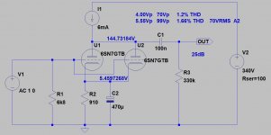
Many thanks for doing the simulation. It corresponds almost perfectly with the real situation, as measured, except for the distortion figure, which I am unable to measure, but looks like what I expected. I am driving the amp with a small professional mixer, which can deliver +24 dBU (17.36 Peak) of drive for the 6SN7 - way more than is needed to reach sufficient drive for the 300B with lots of voltage swing on the 300B grid. BTW, what simulation software are you using?I'm not sure, that this is the most decent driver for 300B.
Single stage 6SN7 has no enough gain -even with CCS load-, thus at higher input level this stage is the limiting factor.
That's great, thanks. I'm very happy with euro21's simulation. I think that has copper-fastened the final design for me. I'm now going to painstakingly attempt to draw out a combination Ia- Va set of curves for the paralleled 6SN7s, using half its plate resistance and different values of voltage and current on the X and Y axes. I might need lots of graph paper.goddlediddles,
In Post # 118 you asked how you could draw the load lines for parallel operation. Use that set of curves.
Draw a horizontal line across the curves at 3mA (each triode gets 3mA, for 6mA total).
910 Ohms x 6 mA = 5.46V 5.46V is the bias (about 3/4 of the way from the 4V grid line and the 6V grid line. Draw a circle around the 3mA line at that grid voltage.
Perhaps the current source impedance is 600k Ohms, I am not sure.
600k Ohms in parallel with the 300B's grid resistor of 300k = 200k
But each 1/2 of the 6SN7 'sees' 400k, because the other 1/2 is driving the same 200k load too (they are aiding each other).
So draw a 400k load line, and now you see the result of signal that causes grid voltage change, and the resultant plate voltage change.
Does that help?
Does your amplifier have enough gain to work with all your signal sources, and for all the speakers that you will use with the amp?
At 130 posts, we are in danger of a moving target (which can never be hit). We could go on forever, but lets settle on a design.
At 3mA plate current, the 6SN7 rp is much higher than the 7700 Ohm spec.
You can estimate the rp at that current by measuring the slope of a single grid curve when the plate current is 3 mA (How much does the plate voltage vary as the plate current is varied from 2 mA to 4 mA). delta plate voltage / delta plate current
delta plate voltage / 0.002A
You can estimate the rp at that current by measuring the slope of a single grid curve when the plate current is 3 mA (How much does the plate voltage vary as the plate current is varied from 2 mA to 4 mA). delta plate voltage / delta plate current
delta plate voltage / 0.002A
Yes, but I will go the whole hog, and draw out the actual curves fully, using the original General Electric data sheet version as a starting point. This might take some time.At 3mA plate current, the 6SN7 rp is much higher than the 7700 Ohm spec.
You can estimate the rp at that current by measuring the slope of a single grid curve when the plate current is 3 mA (How much does the plate voltage vary as the plate current is varied from 2 mA to 4 mA). delta plate voltage / delta plate current
delta plate voltage / 0.002A
Does it allow for specific CCS devices or just generic?LTSpice.
Does it allow for specific CCS devices or just generic?
LTSpice has some depletion MOSFET model.
Are you read Ale's blog?
CCS PCB – Bartola(R) Valves
Yes, I read that before settling on the IXCP10M90S. A single chip with one resistor suited me because of limited space. I'm listening to the result for weeks now, and I am totally happy with the tone of the amp. Thanks.
And this is how long I have been listening to amps and speakers. Try putting a date on that!Yes, I read that before settling on the IXCP10M90S. A single chip with one resistor suited me because of limited space. I'm listening to the result for weeks now, and I am totally happy with the tone of the amp. Thanks.
Attachments
I finally have an answer to the question you asked. The transformer secondary DCR per 400V section is 47Ω, and the primary DCR is 5.4Ω. The turns ratio is 240/400 = 0.6. So there is 15Ω reflected into the secondary, giving a combined effective DCR per section of 47+15 = 62Ω.I don't think so.
Secondary low DCR (BTW how many Ohms?) AND first capacitor larger that needed is the rectifier killer.
Last edited:
- Home
- Amplifiers
- Tubes / Valves
- Problem using Hammond 126C IST