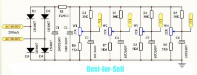
This is a biasing cct for Class AB fixed bias PP UL 6L6GCs in two monoblocks I built circa 1960. And one of the amps, both still running but not today.
The cct may give you some ideas to work on.")
Very nice- and quite similar to the balance pot style that Pete Millet implemented on his PCB.
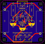
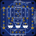
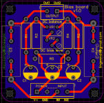
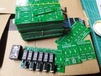
Pretty simple, but this sounds like a job for a custom PCB. I had downtime at work (for once!) so I decided to start implementing one on a 50mm square, and it will also incorporate the input capacitors on board. Should be handy and cheap to have a few made. Going to chew on it a few days, add some extra holes to accommodate multiple capacitor sizes/lead spacing (as it is it's really best for axial lead types) and hopefully have something useful together to make a not-so-fun thing to do on veroboard a bit more pleasant. Currently its set to use Bourn 10-turn trim pots, but I will add a few more holes to accommodate alternate parts as well. the electrolytics have 5mm lead spacing. Swooky round corners this time, and a ground plane since there is so little current here.
I was planning on using 10R cathode resistors to enable easy measurement of idle current, and if I can find a set of cheap panel meters I may throw them in at some point. Looks like this will be just the ticket.
Attachments
Last edited:
Went bigger on the resistor footprints to accomadate the larger types some folks like to use, and cleaned it all up a bit. Still need to work on how I'm going to do the silkscreen labels for the inputs and outputs, and think of a clever name for the board. Bias Buddy? Hmmm.
Attachments
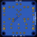
I figure for 25k pots the worst case dissipation will be a 40% of the supply voltage, so assuming something like 100 volt supply you're at .064W dissipation, which should be fine with a quality cermet trimpot. Worst case a larger pot could be wired offboard?
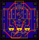
I've attached the semi-final state of the board. Looks pretty self explanatory, but I'll draw up a specific schematic soon, but it's basically the one jhstewart posted, with added capacitors across each end of the balance trimmer to the negative rail, resistors tied to the negative rail rather than ground as in the Millet version, and without the meter circuitry (which, incidentally, is the same as the Millet circuit just with the added resistor inline with the pot, which is a good feature to limit adjustment and pot dissipation.) so that it is easy for most builds. Mostly the Millet version.
Once I get this to a point I'm happy with I'll do a 50x100mm dual version as well.
Attachments
Last edited:
that inline resistor with the pot will soak up a lot of the dissipation though, so worse case it should still be in spec. I don't plan on using it for really negative rails over 100 volts or so, the excess will be soaked up in the power supply filtering if needed. If you know of any pots suitable for PCB mounting that are readily available to work at higher dissipation I'm all ears in making them fit the PCB too
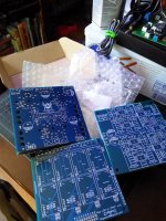
I use the free online EasyEDA editor, and my orders so far have been with JLCPCB. Shipping has been fast, and quality has been excellent. I've used them for a dozen designs (not all of them audio) now. Pretty affordable if you keep your PCBs to 100mm square. five PCBs for $2 special going on currently (yes, $2!) so I want to order some of these pretty soon. DHL express (shipping to your door in several business days) is $16USD if you order 5 or 10 of these boards, pretty affordable.
Attachments
Last edited:
No problem man. It's a very easy site to use, and I haven't had a parts outline that I needed that wasn't included. Pretty straightforward and easy to get into, and a very enjoyable (for me, at least) task, especially for straightforward circuits. You can easily import images for logos, oddball text, etc.
Well, chassis are still sitting, I've deburred the holes, added a few ventilation holes near the output sockets, and all the jacks, fuse receptical, etc are drilled and fitted. Almost time for paint, but now I'm contemplating adding a few more holes near the power and filament transformers, since the PSU PCB and filament dropper resistors (the filament trafos put out ~14 volts) will be near there. All the transformer metalwork has been cleaned up and hit with hammertone paint, which is a great way to hide dings and imperfections.
Projected tentative operating points-
Front end and concertina with 6CG7/6FQ7:
Supply voltage: ~270 volts
Grid voltage: -2.8 volts (via cathode resistor)
Operating current: 3.8~ mA
Anode resistor: 47k
Anode voltage: 100 volts (yes, it's low, but works well at low signal swing like we will get here)
Cathode resistor: 750~ ohm (will be in parallel with feedback resistor, so likely will end up between 820~1200 ohm)
Projected gain with a bypassed cathode is ~14
Direct coupled to a 6CG7/6FQ7 concertina (via grid stopper as a jumper) with 22k anode/cathode loads.
Driver stage/differential with 6N1P(6Н1П)
Supply voltage: ~270 volts
Grid voltage: -3.7 volts (via cathode resistor)
Operating current: 3 mA
Anode resistor: 47k
Anode voltage: ~180 volts
Cathode resistor: 1230~ ohm per cathode
Projected gain with a bypassed cathode is ~34 per triode
Not sure if I'm going for individual bypassed cathodes or a tail with a CCS down to the negative rail.
Output stage with 12AV5GA (mostly GE and RCA types of identical construction)
Supply voltage: ~270 volts
Grid voltage: -45~50 volts (fixed bias)
Operating current :35~50mA
Cathode resistor: 10 ohm (1-3 watts, matched as close as possible for cathode current measurement)
6K:8 (3K:4) plate-to-plate "20 watt" no-name output transformer
Since the 6AV5GA and their kin can take a good bit of current past their rating safely with no adverse lifetime or reliability issues in audio applications, I think I'll bias them for about 14~15 watts combined anode/screen and see how they do. I have plenty of 12AV5GA's but don't plan to abuse them necessarily.
Still need to dig through my parts to see what coupling caps I'll be using, as the only four I have on hand currently are green Russian surplus PIO k42y 100nF, 250 volt (my last four!) and that will dictate what I use for grid leak resistance. I have some X1 types on the slow boat from deep in Red China in 100nF and 220nF I'm waiting on, so might just use them so they all match.
Also, I decided on the purple, screw it lets be a little silly.
Projected tentative operating points-
Front end and concertina with 6CG7/6FQ7:
Supply voltage: ~270 volts
Grid voltage: -2.8 volts (via cathode resistor)
Operating current: 3.8~ mA
Anode resistor: 47k
Anode voltage: 100 volts (yes, it's low, but works well at low signal swing like we will get here)
Cathode resistor: 750~ ohm (will be in parallel with feedback resistor, so likely will end up between 820~1200 ohm)
Projected gain with a bypassed cathode is ~14
Direct coupled to a 6CG7/6FQ7 concertina (via grid stopper as a jumper) with 22k anode/cathode loads.
Driver stage/differential with 6N1P(6Н1П)
Supply voltage: ~270 volts
Grid voltage: -3.7 volts (via cathode resistor)
Operating current: 3 mA
Anode resistor: 47k
Anode voltage: ~180 volts
Cathode resistor: 1230~ ohm per cathode
Projected gain with a bypassed cathode is ~34 per triode
Not sure if I'm going for individual bypassed cathodes or a tail with a CCS down to the negative rail.
Output stage with 12AV5GA (mostly GE and RCA types of identical construction)
Supply voltage: ~270 volts
Grid voltage: -45~50 volts (fixed bias)
Operating current :35~50mA
Cathode resistor: 10 ohm (1-3 watts, matched as close as possible for cathode current measurement)
6K:8 (3K:4) plate-to-plate "20 watt" no-name output transformer
Since the 6AV5GA and their kin can take a good bit of current past their rating safely with no adverse lifetime or reliability issues in audio applications, I think I'll bias them for about 14~15 watts combined anode/screen and see how they do. I have plenty of 12AV5GA's but don't plan to abuse them necessarily.
Still need to dig through my parts to see what coupling caps I'll be using, as the only four I have on hand currently are green Russian surplus PIO k42y 100nF, 250 volt (my last four!) and that will dictate what I use for grid leak resistance. I have some X1 types on the slow boat from deep in Red China in 100nF and 220nF I'm waiting on, so might just use them so they all match.
Also, I decided on the purple, screw it
lets be a little silly. Nice...
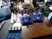
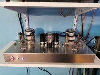
I just finished my 6P34P pentode build.
6F12P VA/PI as per my usual, no driver since it's pentode.
6F12P B+ 400V
6P43P B+ 330V
6P43P Screens 185V (0D3 shunt regulator on top of a 36V zener from a 220V B+)
So far it's not bad, but not much power more than triode mode, and worse output (square waves at 10kHz don't exist, more like a morph of a sin and a square together). Still, it's quiet, and the SMPS starts into the bloody load! Yay me!
Attachments
Very clean looking, nice layout.
Yeah pentode mode of the 6P43P didn't look all that great to me, maybe the curves kinking up near lower voltage are making things wonky? I wonder how they would do in UL or with "schade" plate-to-driver-plate feedback? Would need a differential driver for that to work though. Might be a good experiment, but the 6F12P wouldn't work for that.
Worst case just pop in a set of EL86/6CW5, like my daily driver build uses?
Thank you. I built it with SS bolts instead of the black ones this time. I'm thinking about making covers for the transformers out of soup cans but I kind of like the naked look, you know?
6F12P would work if you move the PI to the driver? Like 6F12P gain into 6F12P gain into 6SN7 LTP or something? Or the 6SN7, one grid driven, the other grounded with a CCS for the cathode and no bypass?
As far as 6CW5, I only have one. I have like 50 6P43P i think. I also realize the audible difference between 10W and 20W is not much, and I have a bloody cold complete with a stuffed sinus cavity.
With the bigger sweep tubes, I can run them with no load so I can switch from one amp to the other to compare, but these ones with the smaller OPTs and the 6P43Ps like to oscillate with no load. You can see it in the 0D3 on the fixed bias pentode amp, and as one red plate on the triode version with electronic auto grid bias. I really think it's a problem with the switch though. Only the right channel has issues.
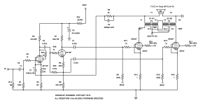
Actually, I effed up when I built it as follows.
R7 and R8 were supposed to be 47k but I used 22k. When the voltages were wrong, I changed R6 from 1k2 to 600. Maybe the PI can't work into that load? OTOH when i use 47k, I was also using 560V instead of 400V
R7 and R8 were supposed to be 47k but I used 22k. When the voltages were wrong, I changed R6 from 1k2 to 600. Maybe the PI can't work into that load? OTOH when i use 47k, I was also using 560V instead of 400V
Attachments
The Triad transformers won't do much at 10 KHz, made for line frequencies. They look like competition to the Hammond 182 Series.
But probably OK for listening to background music. Or maybe public address. For your own curiosity did you measure the OP stage total plate current when run at HF, high level? That extra goes to heat the transformer core & coils.
The screens would be running pretty hot too, the loadline would be a large, open ellipse.
I'm still not very familiar with the 6F12P, so I'm not sure if the operating point you're using is ideal or not. I need to spend some more time with the datasheet and lash something together. I considered something using one of the pentode per side on a longtail pair, with the triode connected as a cathode follower directly to the plate of the pentode, it should have excellent swing at low output impedance. Think Pete Millet's engineers amp but with cathode followers between the driver plates and grid. He curves on the pentode look fantastic, so may be worth running them this way for pentode connected sweeps with plate to driver feedback...
I know from past experience that the antek toroids I use have good HF performance, but haven't tried the triad units.
The Triad transformers won't do much at 10 KHz, made for line frequencies. They look like competition to the Hammond 182 Series.
But probably OK for listening to background music. Or maybe public address. For your own curiosity did you measure the OP stage total plate current when run at HF, high level? That extra goes to heat the transformer core & coils.
The screens would be running pretty hot too, the loadline would be a large, open ellipse.
I know from past experience that the antek toroids I use have good HF performance, but haven't tried the triad units.
- Status
- This old topic is closed. If you want to reopen this topic, contact a moderator using the "Report Post" button.
- Home
- Amplifiers
- Tubes / Valves
- opinions on williamsonish build?