PS- I never built a Williamson, everyone else did that.
I had a friendly chuckle at this admission! The “great jhsteward never built a Williamson”, imagine that! But I have immensely enjoyed reading about your “other experiments” over the years. Thanks for all those experiments and contributions over the years.
Last edited:
Thanks for the kind words, guys. I'm honoured.
Funny, jhstewart never build a Williamson, I've never build the Mullard 😛
Funny, jhstewart never build a Williamson, I've never build the Mullard 😛
Also, don't feel bad. I don't know SPICE either. I use TCJ Push-Pull Calculator - Download which is half price today.
As far as the 26LW6 tubes François has, run the heaters from a 24V SMPS... Close enough is good enough.
The amp schematic I posted earlier in this thread will work for any amplifier you want to build. The only variable being the output tubes chosen, and the optimal OPT (1k3 for big tubes like *LW6, 3k for the small ones like 6BQ6 if you are using the interleaved toroidal idea, Triad VPT18 and VPT12 respectively, bigger is better) and the gNFB cap.
Whatever VA rating you get will be close to your rated audio power at 30Hz, the higher VA, the lower the DCR, and the better it all works but don't bother getting 250VA coils for smaller tubes... It's past the point of diminishing returns IMHO.
Those bigger VPT coils also work for SE if you don't want a lot of power. I have had one tube out of the PP pair stop working but I couldn't tell because it didn't sound dioded like when you blow half your transistor output 😛.
I wasn't listening to it loud but I only noticed when I was using an IR thermometer to measure the temperature and found 3 tubes were 200c or so, and the other was only 65c...It sounded "fine". There was a 120mA mismatch, and the load was 1/4 of 1k3, too.
Ah, the TCJ Push-Pull Calculator at half price! Too bad I don’t own a PC with Windows below 10 anymore. I think I read somewhere Windows 10 will not run the Calculator.
Koda, thanks for the ballpark on the xLW6 and other sweep tubes. I tucked those away for later contemplation.
Lingwendil, your 6AV5 project is coming along nicely. Looking forward to your assessment after the monoblocks are up and running, and hopefully not humming 🙂
Koda, thanks for the ballpark on the xLW6 and other sweep tubes. I tucked those away for later contemplation.
Lingwendil, your 6AV5 project is coming along nicely. Looking forward to your assessment after the monoblocks are up and running, and hopefully not humming 🙂

Lingwendil, your 6AV5 project is coming along nicely. Looking forward to your assessment after the monoblocks are up and running, and hopefully not humming 🙂
Thanks man, the next hole to cut is the IEC jack, which is the single thing I hate most about chassis construction 🙂, followed by the holes for the fuseholders.
The IEC jacks I have are the standalone kind, without power switches or fuseholders, so a tad more work.
After that I can do some final cleanup of the holes, figure out what I'm doing for power switches, and prep it all for paint, that way I can let it cure for a few days and then start on assembly. I just need to dig out some nine pin sockets for the front end, all the ones I have on hand already have circuits assembled to them, and I'm not keen on stripping the old components off.
I'm thinking of a black semigloss, with maybe a light texture? Not sure. I will likely put a 1x3.5x7.5" wood side piece on either end, but I'm not sure yet. I will leave those holes out until I find suitable wood.
It's taking all my willpower to not paint these things purple, I've been wanting to build something purple for a while (my favorite color) but I think it would clash with the old school look of this build. Maybe I'll do purpleheart for the wood side pieces? Hmmm.
I use these: 10 Pcs IEC 320 C14 Male Plug 3 Pins PCB Panel Power Inlet Socket Connector | eBay
Is that what you use? How do you make the hole? I use a cutting wheel on a Dremel, because I'm too cheap to buy the Greenlee punch. https://www.amazon.com/Greenlee-60031-Rectangle-0-750-Inch-1-140-Inch/dp/B00204DWQI
Is that what you use? How do you make the hole? I use a cutting wheel on a Dremel, because I'm too cheap to buy the Greenlee punch. https://www.amazon.com/Greenlee-60031-Rectangle-0-750-Inch-1-140-Inch/dp/B00204DWQI
Last edited:
Yeah, that's what I use. I mark it out, drill the corners with a 1/8" drill bit, then use a cutoff wheel to do most of it. Then clean it up to final fit with a file. These are my last two jacks so I might just grab a few combination units that have the fuse and switch built in next.
You're better than me. I mark the hole with a sharpie and plunge cut it. It's always a little bigger than it needs to be and I never clean it up because it's on the back and nobody sees it anyway haha.
Lately, I've been using a small SMPS and a latching relay module to get touch power 🙂
Lately, I've been using a small SMPS and a latching relay module to get touch power 🙂
I use a nice sharp awl to scribe the outline while using a steel ruler as a straight edge, and cut just next to it so I can creep up on it with a file. It takes more time but turns out nicer. Arguably unnecessary but it feels good to do it this way 🙂
The working (DC) resistance is not the same as the AC resistance, nor is it the leakage reactance. These are three different items in themselves.I'll try to measure the winding resistance tonight, but yes, 6K:8, I figured this would be a reasonable choice here. And if I use them with 4 ohm speakers it would still be a reasonable choice.
The AC resistance is higher than the DC resistance because skin effect & proximity effect get in the way. At the higher frequencies there is less copper in use in the in the conductors (skin effect), especially near & at the center of the pack (proximity effect).
But on the other hand DC resistance can give us a pretty good guess how your OPT will perform. Lower is better, who would have thought??🙂
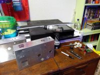
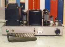
Slowly but surely getting along. Drilled all final screw holes and fit them to size. Went with stainless hardware simply because I could pilfer as much as I needed from work with the lab guys blessing 🙂 I've been doing little bits here and there but haven't made it to the garage to cut out the IEC jack holes, but at least laid them out and drilled out the corners of the openings. I'm working in the living room with a cordless drill and a set of files while my son plays and watches TV. Later tonight or tomorrow morning I'll cut and fit the IEC holes, then start final mockup before I paint everything.
Attachments
Looking good sofar. How thick is the metal the aluminum chassis is made from? In the photo it appears thicker than Hammond Chassis's I've used.
I believe it's 1mm? It's a bud industries aluminum. If I had heavier transformers I think it would be a bit on the light side, but with how everything is fairly close to the edges and corners it seems fine for this project. Worse case I could reinforce it with scrap aluminum angle but I don't think it will be necessary. They were $11 each reduced on Amazon, and I've used a handful in the past with great results, easy to work with and well made.
While out running errands with the family today I'll try to pick out some spray paint. I'm thinking textured wrinkle or hammertone for the transformers to hide the little nicks and dings. Black or very dark grey most likely. Still not sure on the chassis enclosures themselves- but I have two cans of purple unused in the garage I may go with if I don't find anything compelling at the hardware store 🙂
While out running errands with the family today I'll try to pick out some spray paint. I'm thinking textured wrinkle or hammertone for the transformers to hide the little nicks and dings. Black or very dark grey most likely. Still not sure on the chassis enclosures themselves- but I have two cans of purple unused in the garage I may go with if I don't find anything compelling at the hardware store 🙂
Good on you, buddy!
Luckily I like the raw aluminum look, because I'm rubbish at painting, and far too lazy. If I was to paint it, I would need to build it first, and then mask and paint. I painted a chassis once. The paint chipped easily, but I didn't let it dry for a week or cure it in the oven. It was cool though. Purple metallic that was supposed to look like anodizing with clear coat.
It was this: Dupli-Color MetalCast Paint, 311g | Canadian Tire
All my stuff for the past 25 yrs has been experimental, so I put a lot more effort into how the underside looks. That also makes it easier to get the measurement data I want. And make the changes when I'd like to get more comparative results.
I usually use some wooden strips available at the hdwr stores to build something the chassis can be inverted on. That is the way the amp spends most of its life, on the test bench. I do some listening tests but not a lot. My hearing is shot. The extensive measurement data tell me when things are good or otherwise. But that is the objective.
This experimental amp, what is possible with 2 volt filament tubes? So PP 33s in triode or UL, can be driven into Class AB2. 33 triode connected as a driver thru a Hammond IT. And a 1B5/25S front end.
I still listen to the Stones, Pink Floyd & lots of rock. I've a rock station on now as I do this. But Bach or some acoustic guitar is great as well.🙂
Should I dare saying 'anything but C&W'?😀
Attachments
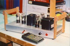
^ that's a cool project, and the wood rails on either end are a good idea. I have some scrap wood I plan to make a pair of frames to support these while working on them upside down. One of my goals this time is to make it look nicer than usual, and I think that won't be terribly difficult given the topology I'm going with and the use of a tag strip or two. I'll be making up a PCB for each to support the bias circuitry, the rest will be point to point.
The last few years my taste in music has changed a bit, but is still kind of all over the place. Most recently I've gotten into Dungeon synth (check out "The Dungeon Synth Archives" channel on YouTube for an idea) for background music at work when I'm in the office, or some medieval style (Fief is a good artist) classical, mostly instrumental. While driving or at home it's mostly rock/metal with female leads, such as Lacuna coil, Nightwish, Within Temptation, Garbage, and the occasional bit of some more usual older stuff like Depeche Mode, New order, or similar. Queensryche and Megadeth have been in circulation lately too.
Assuming C&W is country and western, well, I've only ever cared for a very small amount of that sort of music. Marty Robbins- Big Iron is a favorite of mine, however. 🙂
I don't care for hip-hop or rap as a rule, so it's very rarely any of that comes through our house 🙂
Last edited:
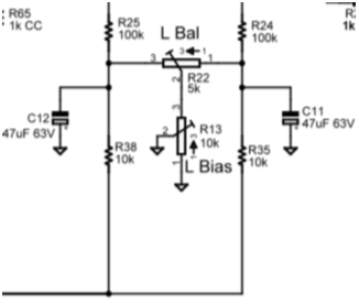
While I have some time at work to think on things, I'm trying to look at bias circuits. It's been quite a while since I built anything with fixed bias, so I'm making sure to do it as simple but effective as possible. For those of you who do this often, do you find a separate bias pot per grid is best, or a single bias pot with a balance pot is easier? I see that on Pete Millet's Engineer Aamplifier he does it with a balance pot for the regular version, and separate pots per tube for the monoblocks. I figured his work is a fine place as any to borrow from here.
Master adjust with balance from stereo PCB-
Individual adjustment from monoblock PCB-
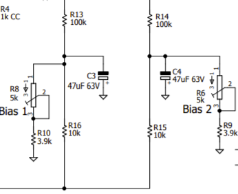
Any input? I almost think the balance pot version would be a bit better, as minor adjustments would be easier after setting the level for both tubes, rather than cranking two pots down independantly, but realistically once the initial level is set at build time it doesn't seem to matter much, and parts count is almost the same.
Master adjust with balance from stereo PCB-
Individual adjustment from monoblock PCB-
Any input? I almost think the balance pot version would be a bit better, as minor adjustments would be easier after setting the level for both tubes, rather than cranking two pots down independantly, but realistically once the initial level is set at build time it doesn't seem to matter much, and parts count is almost the same.
Attachments
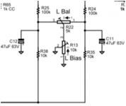
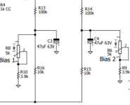
Safe Bias & Balance Measurement
This is a biasing cct for Class AB fixed bias PP UL 6L6GCs in two monoblocks I built circa 1960. And one of the amps, both still running but not today.
The cct may give you some ideas to work on.🙂
This is a biasing cct for Class AB fixed bias PP UL 6L6GCs in two monoblocks I built circa 1960. And one of the amps, both still running but not today.
The cct may give you some ideas to work on.🙂
Attachments
- Home
- Amplifiers
- Tubes / Valves
- opinions on williamsonish build?