The Triad transformers won't do much at 10 KHz, made for line frequencies. They look like competition to the Hammond 182 Series.
But probably OK for listening to background music. Or maybe public address. For your own curiosity did you measure the OP stage total plate current when run at HF, high level? That extra goes to heat the transformer core & coils.
The screens would be running pretty hot too, the loadline would be a large, open ellipse.
There's nothing wrong witht he HF response. 50kHz sine is fine, just the square waves aren't great on this set. Using two 250VA coils instead of 25VA, and running 200mA instead of 40mA makes a big difference (trioded sweep vs small pentode).
That's a beautiful construction. Luv the mysterious stacked OPT's. Pentode outputs need output Zobels more than most; maybe some right across the output terminals? 0u1 F and 10R or 15R? Can't hurt; might fix the oscillation too.
All the best fortune,
Chris
Thanks for the tip. I'll try that.
The screens would be running pretty hot too, the loadline would be a large, open ellipse.
Why is that?
Test for HF & LF Roll Off Of OPT
Your comment regarding poor reproduction of the 10 KHz square wave got me wondering what the useful band pass of the power type PTs really is. So at the risk that some of the whiz's out there probably know how to do this already, here is an easy way to do get the information while in the amplifier, with an absolute minimum of surgery. First & foremost, this is NOT a test of the amplifier. It is a test of the OPTs. In order to do that here is what needs to be done & why.
The NFB MUST be disconnected. NFB tries to keep the amp gain constant by controlling the gain where the NFB is applied. In this case that would be the first stage. If there was an HF shelf on the plate of the first stage that would need to be disconnected as well.
The output stage MUST be run as pentodes, that insures a relatively constant drive to the OPT(s) in test. So when the OPT response drops off the measured voltage goes down with that.
Start by setting a reference point at say 400 Hz, the useful mid-band. Then crank up the frequency from the signal generator & note the frequency where there is a 3 db drop in the response. Do the same the other way going down to the minus 3 db drop. On an AC VM that would be at 0.707 of the reference volts
Very straight forward & easy to do. If you believe your scope & SG should be OK. I've never bought line type transformers for this kind of application, otherwise I'd have done this some time ago. Useful information for any designer of audio amps.
I think that would tell you more about the pentode amplifier than the transformer. Seems like driving the OPT with a source/cathode follower would make more sense if we're trying to test the BW of the transformer only. The tests I did already on another amp using trioded sweeps the 250VA coils showed about 15Hz - 50kHz within 3db, and within 10db, the coils will pass 5Hz - 500kHz.
Driving the transformer in test with a voltage source will not get the information required. Both Triode & CFs are voltage sources. So you may see what looks like exceptional performance but it is not that kind of data that a designer needs.
Triode amps can drive a low cost OPT very well. But that is not the data required.
Don't confuse subjective observations with the objective. The subjective would be a listening test, not easily repeated at another place &/or time by someone else. And includes all the other parts of the system & environment.
An objective test excludes all the other variables as much as possible & zeroes in on the object to be tested. In this case it is the OPTs used, not the amp or how it sounds.
Do the test the way described, that is the information required where a serious designer starts. Doesn't take long, wish I had one of those PTs, I'd have the answer in an hour. Or would have done that soon's I had one to try.
Any pentode? How much idle current? At what power? So many missing variables. If I just test using the amp it's in with no NFB i'll get a result, but what if I used a more powerful pentode or a higher current? won't these variables change the outcome?
FWIW this is the main reason i usually build triode amplifiers. Less f*ckery.
Also, I see you're near Toronto. If you say it only takes an hour and you already know what you're doing, maybe I should being over some coils one day.
FWIW this is the main reason i usually build triode amplifiers. Less f*ckery.
Also, I see you're near Toronto. If you say it only takes an hour and you already know what you're doing, maybe I should being over some coils one day.
Last edited:
Aside from the available power, triodes always drive the load better. For a number of reasons, some I've covered on this forum in the past.
One watt is plenty for this kind of test. And the amp operating point simply set to something that doesn't cook the parts.
Can also measure D% for your amp while you are here with the NFB hooked up or not. I've been using Pico Technology virtual measurement into a laptop for several years. Gave away my 2-channel, 100 Mhz scope several years ago. And real power measurement using MetraHit 29S DMM with direct Watts results. So we can be confident with the results. I don't listen much anymore, my left ear is shot.
I live not far NW of Toronto in King Twp, just a short way up Hwy 400. If you like we can set up something in Jan or Feb.
So, after some thinking, I think I'll go for a differential/LTP for the first stage, rather than the voltage amplifier and concertina. My reasoning mainly being that due to the lower voltage I have to work with (~280 or so before filtering) the concertina wouldn't have enough headroom to have decent voltage across the triode if it was direct coupled to the voltage amp plate. This could be alleviated by floating it and capacitor coupling, but I really don't want to introduce another capacitor into the chain, as we have a couple pairs already. Besides, I'm already going a different direction than my norm by going triode coupled on my output stage, so might as well do the front end different anyway as a nice change of pace.
Time to look at loadlines again, and pick a point for the 6FQ7 of around ~165-180 plate voltage. Probably going for a BJT or DN2540 cascode for the CCS.
Time to look at loadlines again, and pick a point for the 6FQ7 of around ~165-180 plate voltage. Probably going for a BJT or DN2540 cascode for the CCS.
I do plan to use GNFB. Maybe I should go for 6N1P for both differentials then? That gives me a mu of 35 on both, and identical parts values if I so desire
I do have maybe six total of 6N1P on hand, same pinout, same heater power as the 6FQ7/6CG7 anyway. The symettry of using the same tubes for both stages sounds nice conceptually anyway...
Looking over the curves from Tube Tester Files - 6N1P - 6H1? I think I want to go higher on the plate current, something from 6-8mA per triode looks better, higher mu and lower plate resistance for better AC drive . This would also allow me to use lower value plate resistors (22k~30k) that I have on hand without having to buy any more. A DN2540 cascode for the CCS under each LTP should work well from 10mA on up, too.
Hmmmm.
Last edited:
....The normal Williamson build used a hi mu triode like 6SL7 or 12AX7 on the front end. But if you don't intend to use NFB, probably OK.
Williamson used L63 front-end. L63 is 6J5G. There's no twin-6J5 but 6SN7 is usually considered same-as for most purposes. (Williamson's "New Version" specifically lists 6SN7.)
http://www.r-type.org/pdfs/dtnw-amp.pdf
A Williamson without NFB misses the whole point of Williamson's thinking.
Williamson used L63 front-end. L63 is 6J5G. There's no twin-6J5 but 6SN7 is usually considered same-as for most purposes. (Williamson's "New Version" specifically lists 6SN7.)
http://www.r-type.org/pdfs/dtnw-amp.pdf
A Williamson without NFB misses the whole point of Williamson's thinking.
You are absolutely correct, I will blame my error on age! Nothing else works!!
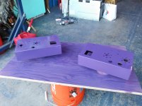
Well, got the first two coats (well, two sets of three light ones each) of paint. It's, uh, a bit more purple than I was imagining, but I like it
Probably going to give it a light sanding tonight, and then two more coats tonight or tomorrow. I realized as soon as the paint hit the second chassis that I forgot to drill a hole in each for the grounding wire's screw though, so I'll do that before the sanding and next coat.
While in the garage I got the ridiculous idea to do one in mint with the design from the Arizona iced tea Green tea can, next time, maybe
Attachments
Last edited:
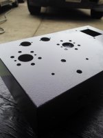
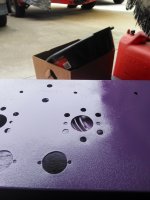
Well, never buying krylon again, I'll stick to rustoleum or duplicolor from now on. After the first two coats looked great, I sanded and put on another coat. They now look wrinkled all to hell. Not sure if I just want to leave it, strip it, or hose it down with hammered paint. If it cures and looks consistent I'm ready to just leave it. I've never had this happen with my usual brands.
Attachments
Back in the day purple was unheard of on TE. All was very conservative, black & grey. Not sure when TEK & HP went to shades of blue. But for someone who has that on their bench, very proud of it. Quite a bit in working order still out there.
The more recent TE shews some of the upstarts using much color to attract attention. That works for a while, than reliability becomes a factor.
Things are moving very quickly, in the back of my head I recall at HP something like seven yrs from introduction to a newer, better version hit the market! Very much driven by the semi buz now,
- Status
- This old topic is closed. If you want to reopen this topic, contact a moderator using the "Report Post" button.
- Home
- Amplifiers
- Tubes / Valves
- opinions on williamsonish build?