I totally agree with what you say ... but no one has made an amplifier with PL519 in direct UL connection as I have here. I have made some experiments with the screen grids on these tubes and found that it is not necessary to connect them with resistors and then they can draw current .. unlimited. It changes performence on the tube to an unknown degree and this is the result. Of course, I was afraid to ruin the tube this way, but it never happened. These tubes are much stronger than I ever imagined. So you are right ... when it comes to regular amplifiers, but not to this one.
Last edited:
Nice work.
How much feedback is applied?
What is the make/model of your output transformers?
The schematic calls for JJ EL509 tubes, is this correct? That doesn't appear to be what is shown in your opening pics though. The JJ EL509 new production tube does not have top caps.
How much feedback is applied?
What is the make/model of your output transformers?
The schematic calls for JJ EL509 tubes, is this correct? That doesn't appear to be what is shown in your opening pics though. The JJ EL509 new production tube does not have top caps.
Aside from using sweep toobz at the OP, looks like a Mullard 5-20. Many versions have been built, some better than others.")
Nice to have the HP THD analyzer. We sold many of those. The sweep cct is unique, it can automatically switch from fast to slow sweep, avoid the ringing of the analoque filter system.
Nice to have the HP THD analyzer. We sold many of those. The sweep cct is unique, it can automatically switch from fast to slow sweep, avoid the ringing of the analoque filter system.
Yes 80mA and 10db. In the beginning I used PL519/5o9..but EL509JJ goes as well.
My transformers are made in Denmark by Overgårds Transformers in Roskilde but Hammond have some that goes to.
AH ! The Roskilde festival. All my childhood
. I haven't heard that name for a long time. Memory cones and go.Great for the OT but without the UL tap %, that would be difficult to replicate your work unfortunately. I understand you may not recall.
Thank you
Brice.
but without the UL tap %, that would be difficult to replicate your work unfortunately. I understand you may not recall.
40%
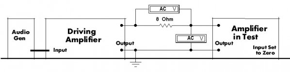
Determination of Damping Factor...........The Easy Way
All we need is a reliable AC VM & a load resistor. And another power amp. Referring to the attachment, one amplifier is used to drive the output of the amplifier in test. The amplifier in test is not driven, the gain control set to zero. The driving amp can be any amp of reasonable spec, very little power is required. Cranking up the signal generator, if 8V appears across the 8R resistor there is One Amp passing thru the secondary of the OPT of the amp in test. Then measure the volts developed across the amp in test secondary terminals. As an example, if that measures one volt the resistance at the amp in test terminals is One Ohm. If the measurements were made on the 8R tap the Damping Factor is 8/1 or simply 8. If a second amp is not available on the shelf, call your buddy! And don’t be surprised at the results, might not be as good as you had supposed. SET amps without NFB manage DF of 3 if not biased off too far. SEUL amps without NFB might make DF of one. NFB will push the DF up.
All we need is a reliable AC VM & a load resistor. And another power amp. Referring to the attachment, one amplifier is used to drive the output of the amplifier in test. The amplifier in test is not driven, the gain control set to zero. The driving amp can be any amp of reasonable spec, very little power is required. Cranking up the signal generator, if 8V appears across the 8R resistor there is One Amp passing thru the secondary of the OPT of the amp in test. Then measure the volts developed across the amp in test secondary terminals. As an example, if that measures one volt the resistance at the amp in test terminals is One Ohm. If the measurements were made on the 8R tap the Damping Factor is 8/1 or simply 8. If a second amp is not available on the shelf, call your buddy!
And don’t be surprised at the results, might not be as good as you had supposed. SET amps without NFB manage DF of 3 if not biased off too far. SEUL amps without NFB might make DF of one. NFB will push the DF up.Attachments
For this test, I used the PPUL 33 amplifier, something I’d built about 20 years ago. Maximum power output for a triode occurs when the load resistance is two times the plate resistance. But the distortion is high, good practice tells us to increase the load resistance to about three times the plate resistance. If the OPT was perfect, DF would be 3. The transformer winding resistances are part of the final result. The measured amp signal at the input is set to zero. The driving amp feeds into the measured amps OPT secondary. The resulting voltage & current are used to calc internal resistance on the 16R tap. For this OPT the primary resistance is 290R, the secondary about 0.5R. A MetraHit 29S Precision DVM & Wattmeter was used. The 33 amplifier is setup to run into Class AB2, so that the output tubes are running at a rather higher plate resistance. The results show that to be the case. 33 PPUL Amplifier Internal Resistance Tests PPUL 33 Amp Test Results. Formatting failed on the last post. Not sure how to clean up what that left.
Not sure how to clean up what that left.Attachments
Missing resistance values in schematic
Thank you for sharing you Final Amp design. I am seriously thinking of building it. I have a pair of Plitron PAT4008 (Menno van der Veen design) outputs that have a primary impedance of 1920 Ohms on my 8 Ohm loudspeakers, with 40% UL taps, 80 watts output. They are high quality toroids which sat on the self for long because I was unsure what to do with them, but they seem perfect for this amp.
Could you possibly provide the resistor values you used around the phase splitter, i.e. cathode resistor, and the resistor between the two grids. I realize these resistor values depend on the tube used, so could you specify which tube among those you listed you are using them with.
Thanks again.
Noticed an unpotted version of Menno’s transformers that could be a suitable output transformer for the “The Final Amp” while I was looking at Menno van der Veen’s website to study the specs of the PAT4008 transformers I own.
100 watts, 2k primary imp., 40% UL taps. It costs only €75.02 (tax included) each.
Might be a good, economical alternative to Hammond 1650TA, especially for Euro builders.
Check it out:Push-Pull : VDV-20100-PPE (XC462)
(No relation to van der Veen)
100 watts, 2k primary imp., 40% UL taps. It costs only €75.02 (tax included) each.
Might be a good, economical alternative to Hammond 1650TA, especially for Euro builders.
Check it out:Push-Pull : VDV-20100-PPE (XC462)
(No relation to van der Veen)
Amplificator SE cu PL519 - Page 5 - Audio pe tuburi - ELFORUM - Forumul Electronistilor
Amplificator SE cu PL519 - Page 2 - Audio pe tuburi - ELFORUM - Forumul Electronistilor
Amplificator SE cu PL519 - Audio pe tuburi - ELFORUM - Forumul Electronistilor
Amplificator SE cu PL519 - Audio pe tuburi - ELFORUM - Forumul Electronistilor
Amplificator SE cu PL519 - Page 2 - Audio pe tuburi - ELFORUM - Forumul Electronistilor
Amplificator SE cu PL519 - Audio pe tuburi - ELFORUM - Forumul Electronistilor
Amplificator SE cu PL519 - Audio pe tuburi - ELFORUM - Forumul Electronistilor
Dear all, I've been linked here by Francois while talking about using EL509 in the Baby Huey circuit.
If jhstewart9 doesn't mind, I would like to simulate the circuit as is and report here the results. Then try to see if shunt feedback (or CCS on the PI) can help even further.
If jhstewart9 doesn't mind, I would like to simulate the circuit as is and report here the results. Then try to see if shunt feedback (or CCS on the PI) can help even further.
Zintolo,
Just to be clear and give credit where due, Tube Mania is the originator of the thread and posted the design in post #1. I assumed Tube Mania is the designer of the circuit listed as Kjeld Pedersen in the schematic.
While he designed and posted many other amplifiers, Mr. jhsteward9 is not the designer of the “Final” amp. He posted some contributions to the thread, especially about measuring the output impedance and by implication the claimed damping factor.
As I wrote elsewhere on diyAudio, I am very interested in the “Final” amp design and would like to build it sometime. Personally, I would welcome your further investigations via simulation and any improvements that could be made would be great.
Last edited:
- Status
- This old topic is closed. If you want to reopen this topic, contact a moderator using the "Report Post" button.
- Home
- Amplifiers
- Tubes / Valves
- Special offer for skilled tube fanatics