The 'Final Amp' is simply a clone of the very popular Mullard 5-10 series of audio amplifiers. Originally designed by Mullard circa 1954 to help sell their products. There is nothing new about the subject amp aside from power. And I've never built a copy of the Mullard circuit & probably never will, there is nothing more to prove.🙂
https://en.wikipedia.org/wiki/Mullard_5-10
https://en.wikipedia.org/wiki/Mullard_5-10
Dear Mr. Steward,
I am delighted by your response! I have thoroughly enjoyed and admired your contributions over the years and find myself surprised that I disagree with you this time. 😀
As far as I know there is indeed nothing more to prove with the “Final Amp” topology, but there is potentially a lot more to be gained through optimization and adaptation (since you have not given us a UL EL509 amplifier design yet, Mullard 5-10 or not, at least to my knowledge). 🙂
What is new about Tube Mania’s contribution with the “Final Amp” is NOT a new topology, and he certainly did not claim that. In fact, he said so. What he contributed is an adaptation of a known circuit utilizing the EL509 sweep tube successfully; tested and lasting over a long time in a conventional UL design at specific operating conditions. The contribution, according to his claims, is that he could use an EL509 PP UL design with B+ of 300Vdc to produce 90 watts at low distortion and with great square wave response, over many years of trouble-free use. (See the claimed results in post #1).
I am not personally able to simulate the design, but would very much like verification of those claims, before I actually build it. (I already have suitable output transformers.) Therefore, I am looking forward to Zintolo’s simulations, as well as any possible improvements through optimization and application of shunt feedback.
I very much hope you will stay involved in this thread and contribute your exceptional expertise and experience.
Last edited:
1.9k to 8 ohm secondary is much simpler to design and very easy to wind and that is possible with the low b+ used....i am thinking 3 sections primary and two sections secondary....
low impedance output traffos are simpler, i have done a 600 ohm to 8 ohm secondary opt for 6c33 many years before...
1.9k to 8 a turns ratio of 15.4
also the higher b+ for the phase splitter and regulated supply for the input voltage amp is now very easy to do with a lot of mosfets now ubiquitous and cheap, something not easily available 20 years or so ago....
Last edited:
Tube mania i believe has given enough information to go by...
Tony, could you then kindly fill in the gaps around the second 6NPi tube in the listed schematic? Providing the specified voltages is not a problem, values of resistors and caps are. Btw, I realize “6NPi” is a typo in the original schematic.
Last edited:
1.9k to 8 ohm secondary is much simpler to design and very easy to wind and that is possible with the low b+ used....i am thinking 3 sections primary and two sections secondary....
low impedance output traffos are simpler, i have done a 600 ohm to 8 ohm secondary opt for 6c33 many years before...
1.9k to 8 a turns ratio of 15.4
also the higher b+ for the phase splitter and regulated supply for the input voltage amp is now very easy to do with a lot of mosfets now ubiquitous and cheap, something not easily available 20 years or so ago....
I appreciate your comment about the relative ease of winding high quality transformers with lower ratios. This amplifies the desirability of designs with power tubes like the EL509, 6LW6 and other high perveance output tubes.
Could we use this thread to work together on a great UL amplifier using those tubes. The problem of course, is the relatively low voltage these tubes can tolerate in a UL design, due to screen voltage fragility. This to me, was the contribution by Tube Mania’s “Final Amp”.
yes, since plate voltages are given, the for the LTP, plate current is 420-270 or 150 volt, now 150/30k is 5ma, so then tail current is 10ma,..since the plate voltage of the input voltage amp is 85 volts, i assume that the cathode voltage of the ltp is at 90 volts, so then the resistor needs to be 90v/10ma or 9k, 9.1 is the nearest standard value and it needs to be rated for 3 watts, the resistor is dissipating about 980mW...
the other resistor can be 1 meg, and the cap at least 0.47 ufd /250vdc at least...polypropylene film caps are getting smaller now...
i think the excitement here would be in the power supply, mosfet regulation for the first voltage amp and another mosfet regulation in the LTP, maybe i going to use a series shunt reg here ala Salas...….
i have a design running in my head as i type this....i will put it into paper...
he says he disliked seriesed psu caps, i can not say i disagree....
but just like in life there are things that you have to do given very limited choices...
sorry FrancoisG, i am not a fan of ultralinear amp, either you go triode or go pentode, there is no middle ground for me...
300vdc finals b+ and 420v b+ for the phase splitter LTP is what i really like, it goes away from traditional designs of the past....i am sure PRR will be happy with it...
sorry FrancoisG, i am not a fan of ultralinear amp, either you go triode or go pentode, there is no middle ground for me...
Tony,
Thank you kindly for you input. Especially as a output transformer winder it is very much valued. But I am curious to know why you are not a fan of ultralinear. I expect you explained that before but please indulge a new generation of readers.
Ultralinear promises the middle ground between your preferred pentode or triode. It provides lower distortion and feedback at the nearly same power output as pentode, as well as lower output impedance.
What is not to like?
Or does it not. Please elaborate.
yes!!
i have a design running in my head as i type this....i will put it into paper...
Yes, Tony, get it out!!
#Please let’s continue our discussion, This post is an artifact of my post to this discussion.
Last edited:
i am a fan of TV tubes....with lower G2 ratings.....with the EL509, 300vdc and ultralinear is not a problem....that is also the reason for the low b+ and the lower A-A opt primary impedance...
1.9k to 8 ohm secondary is much simpler to design and very easy to wind and that is possible with the low b+ used....i am thinking 3 sections primary and two sections secondary....
low impedance output traffos are simpler, i have done a 600 ohm to 8 ohm secondary opt for 6c33 many years before...
1.9k to 8 a turns ratio of 15.4
also the higher b+ for the phase splitter and regulated supply for the input voltage amp is now very easy to do with a lot of mosfets now ubiquitous and cheap, something not easily available 20 years or so ago....
My clone of Norman Crowhurst's Twin Coupled Amp used IRF 840 FETs to regulate the 400V B+ about 20 yrs ago. Those FETs have been on the market for ~35 yrs.
OTOH, I've never wound an OPT, always depended on Hammond for any of my designs. Whenever possible, off the shelf to keep cost down,🙂
Dear all,
I'll do some simulations this evening based on the schematic posted here plus the additional information supplied these days.
I like the idea of the UL with 300V B+ too, for hi-fi and bass amps too.
This, together with the high transconductance makes it perfect to apply shunt feedback too. But it will be later on.
Thank you everybody for all the suggestion and hints.
My clone of Norman Crowhurst's Twin Coupled Amp used IRF 840 FETs to regulate the 400V B+ about 20 yrs ago. Those FETs have been on the market for ~35 yrs.
OTOH, I've never wound an OPT, always depended on Hammond for any of my designs. Whenever possible, off the shelf to keep cost down,🙂
i am member here since 2003, and where i live, those were quite new then...
today there are lots and lots of mosfets to choose from, i make my tube amps with them serving as voltage followers.....
Hi, I've used the following LTSpice models:
...but results are not good on simulations.
Koonw here ( Vacuum Tube SPICE Models ) posted some solutions to improve the design based on the available LTSPICE models:
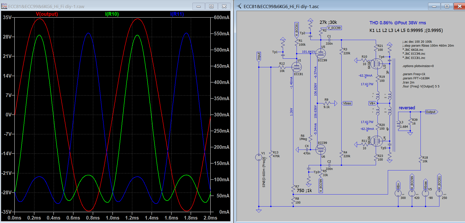
I will update the asc file this evening and upload it.
Code:
*-----------------------------------------------------------------------
* Filename:		6kg6.inc  V2 12/10/97
* Simulator:		PSpice
* Device type:		Power pentode
* Device model:		6KG6/EL509
*			(also 40KG6/PL509 as no heater model)
*
* Author:		Duncan Munro
* Date:			21/7/97
* Copyright:		(C)1997-2000 Duncan Amplification
*
*
* V2 [12/10/97]: Screen current limited to prevent screen current
*		 draw at Vs = 0.
*
* The following parameters are not modelled:
*
*   (1) Heater
*   (2) Grid current is an approximation in the absence
*       of suitable data
*
* Also see comments below, as the Svetlana EL509 is of different
* construction and has different capacitances.
*
* Please note that this model is provided "as is" and
* no warranty is provided in respect of its suitability
* for any application.
*
* This model is provided for educational and non-profit use.
*
* Email queries to [email]postmaster@duncanamps.com[/email]
*
* Pins   A  Anode
*        S  Screen
*        G  Grid
*        K  Cathode
*
*-----------------------------------------------------------------------

.SUBCKT 6KG6 A S G K
*
* Calculate contribution to cathode current
*
Eat	at	0	VALUE={0.636*ATAN(V(A,K)/20)}
Eme	me	0	VALUE={PWR(LIMIT{V(A,K),0,10000},1.5)/17}
Emu	mu	0	VALUE={PWRS(V(G,K),1-(LIMIT{-V(G,K),5,9999}-5)/1150)}
Egs	gs	0	VALUE={LIMIT{V(S,K)/19+V(mu)/4.3+V(A,K)/800,0,1E6}}
Egs2	gs2	0	VALUE={PWRS(V(gs),1.5)}
Ecath  	cc    	0 	VALUE={LIMIT{V(gs2)*V(at),0,V(me)}}
Elim	el	0	VALUE={LIMIT{V(gs2)*V(at)-V(cc),0,99999}}
*
* Calculate anode current
*
Ga     	A     	K     	VALUE={6E-2*V(cc)}
*
* Calculate screen current
*
Escrn	sc	0	VALUE={V(gs2)*(1.1-V(at))+1.2*V(el)}
Gs     	S     	K	VALUE={1.2E-2*V(sc)*LIMIT{V(S,K),0,10}/10}
*
* Grid current (approximation - does not model low va/vs)
*
Gg	G	K	VALUE={PWR(LIMIT{V(G,K)+1,0,1E6},1.5)*50E-6}
*
* Capacitances
* NOTE: Change Cg1 from 37p to 25p for Svetlana EL509
*
Cg1	G	K	37p
Cak	A	K	18.5p
Cg1a	G	A	2.5p

.ENDS
Code:
*ECC81 LTspice model based on the generic triode model from Adrian Immler, version i4
*A version log is at the end of this file
*100h BurnIn of 8 RFT tubes, sample selection and measurements done in Febr. 2020
*Params fitted to the measured values by Adrian Immler, Febr. 2020
*The high fit quality is presented at adrianimmler.simplesite.com
*History's best of tube decribing art (plus some new ideas) is merged to this new approach.
*@ neg. Vg, Ia accuracy is similar to Koren or Ayumi models.
*@ small neg. Vg, the "Anlauf" current is considered.
*@ pos. Vg, Ig and Ia accuracy is on a unrivaled level.
*This offers new simulation possibilities like bias point setting with MOhm grid resistor,
*Audion radio circuits, low voltage amps, guitar distortion stages or pulsed stages.
*                  anode (plate)
*                  | grid
*                  | | cathode
*                  | | |
.subckt ECC81.RFi4 A G K
.params
*Parameters for the space charge current @ Vg <= 0
+ mu   = 68   ;Determines the voltage gain @ constant Ia
+ rad  = 9k5  ;Differential anode resistance, set @ Iad and Vg=0V
+ Vct  = 0.28 ;Offsets the Ia-traces on the Va axis. Electrode material's contact potential
+ kp   = 240  ;Mimics the island effect
+ xs   = 1.4  ;Determines the curve of the Ia traces. Typically between 1.2 and 1.8
*
*Parameters for assigning the space charge current to Ia and Ig @ Vg > 0
+ kB   = 0.22 ;Describes how fast Ia drops to zero when Va approaches zero.
+ radl = 520  ;Differential resistance for the Ia emission limit @ very small Va and Vg > 0
+ tsh  = 10   ;Ia transmission sharpness from 1th to 2nd Ia area. Keep between 3 and 20. Start with 20.
+ xl   = 1.3  ;Exponent for the emission limit
*
*Parameters of the grid-cathode vacuum diode
+ kvdg  = 63  ;virtual vacuumdiode. Causes an Ia reduction @ Ig > 0.
+ kg = 840    ;Inverse scaling factor for the Va independent part of Ig (caution - interacts with xg!)
+ Vctg = 0.1    ;Offsets the log Ig-traces on the Vg axis. Electrode material's contact potential
+ xg   = 1.5  ;Determines the curve of the Ig slope versus (positive) Vg and Va >> 0
+ VT   = 0.165 ;Log(Ig) slope @ Vg<0. VT=k/q*Tk (cathodes absolute temp, typically 1150K)
+ kVT=35m ;Va dependant koeff. of VT
+ Vft2 = 0.6 gft2 = 7  ;finetunes the gridcurrent @ low Va and Vg near zero
*
*Parameters for the caps
+ cag  = 1p6  ;From datasheet ("transfer cap.")
+ cak  = 0p2  ;From datasheet ("output cap.")
+ cgk  = 2p3  ;From datasheet.("input cap")
*
*special purpose parameters
+ os = 1      ;Overall scaling factor, if a user wishes to simulate manufacturing tolerances
*
*Calculated parameters
+ Iad = 100/rad  ;Ia where the anode a.c. resistance is set according to rad.
+ ks = pow(mu/(rad*xs*Iad**(1-1/xs)),-xs) ;Reduces the unwished xs influence to the Ia slope
+ ksnom = pow(mu/(rad*1.5*Iad**(1-1/1.5)),-1.5) ;Sub-equation for calculating Vg0
+ Vg0 = Vct + (Iad*ks)**(1/xs) - (Iad*ksnom)**(2/3) ;Reduces the xs influence to Vct.
+ kl = pow(1/(radl*xl*Ild**(1-1/xl)),-xl) ;Reduces the xl influence to the Ia slope @ small Va
+ Ild = sqrt(radl)*1m ;Current where the Il a.c. resistance is set according to radl.
*
*Space charge current model
Bggi GGi 0 V=v(Gi,K)+Vg0 ;Effective internal grid voltage.
Bahc Ahc 0 V=uramp(v(A,K)) ;Anode voltage, hard cut to zero @ neg. value
Bst   St 0 V=uramp(max(v(GGi)+v(A,K)/(mu), v(A,K)/kp*ln(1+exp(kp*(1/mu+v(GGi)/(1+v(Ahc)))))));Steering volt.
Bs    Ai K I=os/ks*pow(v(St),xs) ;Langmuir-Childs law for the space charge current Is
*
*Anode current limit @ small Va
.func smin(z,y,k) {pow(pow(z+1f, -k)+pow(y+1f, -k), -1/k)} ;Min-function with smooth trans.
Ra  A Ai 1
Bgl Gi A I=min(i(Ra)-smin(1/kl*pow(v(Ahc),xl),i(Ra),tsh),i(Bgvd)*exp(4*v(G,K))) ;Ia emission limit
*
*Grid model
Bvdg G Gi I=1/kvdg*pwrs(v(G,Gi),1.5) ;Reduces the internal effective grid voltage when Ig rises
Rgip G Gi 1G ;avoids some warnings
.func fVT() {VT*exp(-kVT*sqrt(v(A,K)))}
.func Ivd(Vvd, kvd, xvd, VTvd)  {if(Vvd < 3, 1/kvd*pow(VTvd*xvd*ln(1+exp(Vvd/VTvd/xvd)),xvd), 1/kvd*pow(Vvd, xvd))} ;Vacuum diode function
*Bgvd Gi K I=Ivd(v(G,K) + Vctg - uramp(-v(A,K)/mu), kg/os, xg, VT)
Bgvd Gi K I=Ivd(v(G,K) + Vctg, kg/os, xg, fVT())
.func ft2() {gft2*(1-tanh(3*(v(G,K)+Vft2)))} ;Finetuning-func. improves ig-fit @ Vg near -0.5V, low Va.
Bgr Gi Ai I=ivd(v(GGi),ks/os, xs, 0.8*fVT())/(1+ft2()+kB*v(Ahc));Is reflection to grid when Va approaches zero
Bs0 Ai K  I=ivd(v(GGi),ks/os, xs, 0.8*fVT())/(1+ft2()) - os/ks*pow(v(GGi),xs) ;Compensates neg Ia @ small Va and Vg near zero
*
*Caps
C1 A G {cag}
C2 A K {cak}
C3 G K {cgk}
.end
*
*Version log
*i1 :Initial version
*i2 :Pin order changed to the more common order „A G K“ (Thanks to Markus Gyger for his tip)
*i3 :bugfix of the Ivd-function: now also usable for larger Vvd
*i4: Rgi replaced by a virtual vacuum diode (better convergence). ft1 deleted (no longer needed)
;2 new prarams for Ig finetuning @ Va and Vg near zero. New emission skaling factor ke for aging etc.
Code:
*
* Generic triode model: ECC99_AN
* Copyright 2003--2008 by Ayumi Nakabayashi, All rights reserved.
* Version 3.10, Generated on Sun Jan 12 18:46:10 2014
*                Plate
*                | Grid
*                | | Cathode
*                | | |
.SUBCKT ECC99_AN A G K
BGG   GG   0 V=V(G,K)+0.042958289
BM1   M1   0 V=(0.02038404*(URAMP(V(A,K))+1e-10))**-0.86570009
BM2   M2   0 V=(0.63406177*(URAMP(V(GG)+URAMP(V(A,K))/17.952193)+1e-10))**2.3657001
BP    P    0 V=0.005978906*(URAMP(V(GG)+URAMP(V(A,K))/28.313003)+1e-10)**1.5
BIK   IK   0 V=U(V(GG))*V(P)+(1-U(V(GG)))*0.0037149974*V(M1)*V(M2)
BIG   IG   0 V=0.002989453*URAMP(V(G,K))**1.5*(URAMP(V(G,K))/(URAMP(V(A,K))+URAMP(V(G,K)))*1.2+0.4)
BIAK  A    K I=URAMP(V(IK,IG)-URAMP(V(IK,IG)-(0.0033089913*URAMP(V(A,K))**1.5)))+1e-10*V(A,K)
BIGK  G    K I=V(IG)
* CAPS
CGA   G    A 5.8p
CGK   G    K 5.1p
CAK   A    K 0.8p
.ENDS
...but results are not good on simulations.
Koonw here ( Vacuum Tube SPICE Models ) posted some solutions to improve the design based on the available LTSPICE models:
I will update the asc file this evening and upload it.
Attachments
I got a slight different result using PL519 model, the hump in the cathode currents are now gone, Thd down a bit from 0.8% to 0.5%. Please try this model I have revised since Jan 2019.
Code:
*** PL519_P ******************************************
* Created on 10/07/2020 21:23 using paint_kip.jar
* [url=http://www.dmitrynizh.com/tubeparams_image.htm]Model Paint Tools: Trace Tube Parameters over Plate Curves, Interactively[/url]
* Plate Curves image file: pl519_p.png
* Data source link: <plate curves URL>
*----------------------------------------------------------------------------------
.SUBCKT PL519 P G2 G K ; LTSpice tetrode.asy pinout
* .SUBCKT PL519_P P G K G2 ; Koren Pentode Pspice pinout
+ PARAMS: MU=3.553 KG1=13542.79 KP=25.06 KVB=0.008381 VCT=8.483 EX=2.143 KG2=15324.71 KNEE=16.27 KVC=1.654
+ KLAM=6.641E-6 KLAMG=6.16E-4  KD=1.847 KC=41.57 KR1=0.00156 KR2=12.45 KVBG=3.375E-4 KB1=5.08 KB2=2.32 KB3=4.64 KB4=0.1512 KVBGI=2.294 KNK=-0.001728 KNG=0.00235 KNPL=20.59 KNSL=3927.51 KNPR=28374.53 KNSR=31768.06
+ CCG=0.2P CGP=3P CCP=1P VGOFF=-0.6 IGA=0.001 IGB=0.3 IGC=8 IGEX=2
* Vp_MAX=500 Ip_MAX=2000 Vg_step=10 Vg_start=0 Vg_count=22
* X_MIN=143 Y_MIN=102 X_SIZE=869 Y_SIZE=707 FSZ_X=1938 FSZ_Y=1098 XYGrid=false
* Rp=1400 Vg_ac=20 P_max=36 Vg_qui=-105 Vp_qui=300
* showLoadLine=n showIp=y isDHP=n isPP=n isAsymPP=n isUL=n showDissipLimit=y
* showIg1=y isInputSnapped=y addLocalNFB=n
* XYProjections=n harmonicPlot=y dissipPlot=n
* UL=0.43 EG2=190 gridLevel2=y addKink=y isTanhKnee=n advSigmoid=y
*----------------------------------------------------------------------------------
RE1  7 0  1G    ; DUMMY SO NODE 7 HAS 2 CONNECTIONS
E1   7 0  VALUE=  ; E1 BREAKS UP LONG EQUATION FOR G1.
+{V(G2,K)/KP*LOG(1+EXP((1/MU+(VCT+V(G,K))/SQRT(KVB+V(G2,K)*V(G2,K)))*KP))}
RE2  6 0  1G    ; DUMMY SO NODE 6 HAS 2 CONNECTIONS
E2  6 0  VALUE={(PWR(V(7),EX)+PWRS(V(7),EX))} ; Kg1 times KIT current
E4   8 0  VALUE={V(P,K)/KNEE/(KVBGI+V(6)*KVBG)}
E5  81 0  VALUE={PWR(V(8),KB1)}
E6  82 0  VALUE={PWR(V(8),KB2)}
E7  83 0  VALUE={PWR(V(8),KB3)}
E8   9 0  VALUE={PWR(1-EXP(-V(81)*(KC+KR1*V(82))/(KD+KR2*V(83))),KB4)*1.5708}
RE4  8 0  1
RE5 81 0  1
RE6 82 0  1
RE7 83 0  1
RE8  9 0  1
RE21 21 0 1
E21  21 0 VALUE={V(6)/KG1*V(9)} ; Ip with knee but no slope and no kink
RE22 22 0 1 ; E22: kink curr deviation for plate
E22  22 0 VALUE={V(21)*LIMIT(KNK-V(G,K)*KNG,0,0.3)*(-ATAN((V(P,K)-KNPL)/KNSL)+ATAN((V(P,K)-KNPR)/KNSR))}
G1   P K  VALUE={V(21)*(1+KLAMG*V(P,K))+KLAM*V(P,K) + V(22)}
G2   G2 K  VALUE={V(6)/KG2*(KVC-V(9))/(1+KLAMG*V(P,K)) - V(22)}
RCP  P K  1G     ; FOR CONVERGENCE
C1   K G  {CCG}  ; CATHODE-GRID 1
C2   G P  {CGP}  ; GRID 1-PLATE
C3   K P  {CCP}  ; CATHODE-PLATE
RE23 G 0 1G
GG G K VALUE={(IGA+IGB/(IGC+V(P,K)))*(MU/KG1)*
+(PWR(V(G,K)-VGOFF,IGEX)+PWRS(V(G,K)-VGOFF,IGEX))}
.ENDS
*$
Attachments
Thanks again Koonw,
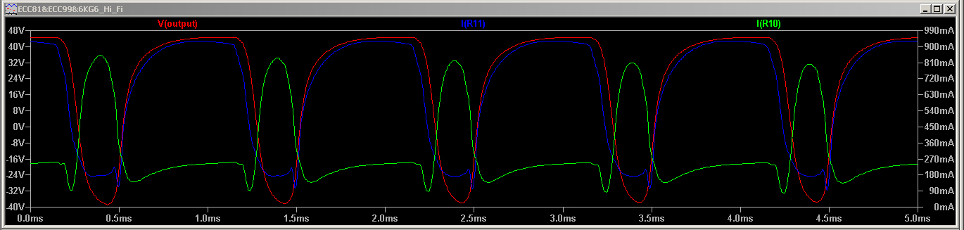
with your model I can go up to 70 Wrms with around 0,24% THD and no oscillations occur.
I tried to lower the idle current, but if I go below -75V for power tubes' grids, no more data is shown. Do you know why?
with your model I can go up to 70 Wrms with around 0,24% THD and no oscillations occur.
I tried to lower the idle current, but if I go below -75V for power tubes' grids, no more data is shown. Do you know why?
- Home
- Amplifiers
- Tubes / Valves
- Special offer for skilled tube fanatics