One thing to be careful of is saying Triode or whatever. It is Rp and linearity trade off. This is neatly defined in the RH34 for example. In PP I would like to see graphs or sims. Also remember the output linearity at the speaker end should have the highest damping factor you can get. 5 would be nice if a no loop feedback design. If you use a low Rp device to drive your pentode output the lineartiy might look supurb. It might sound completely strange as the speaker designer hopes the amplifier's output impedance is below 1 ohm.
I remember Dave Mate saying that all a triode is, is a pentode like device with an internal wire. If you like " inside a good triode is an even better pentode trying to get out ". My words not his.
In most ways this is true. We can buy a good pentode and do anything we like with it. In the past we could.
Being the newspaper man again. When we only had triodes we noticed some were better than others. Lets say by 1924 we started to know how make to order what we wanted. In our imaginary internally degenerated pentode the ECC81's of the day were more pentode like and similar to 6SN7 more like our ideal triode. We then have devices later on like EF184 which is like an ECC81 in ( triode strapped ) that can be true pentode. A packet of crayons so to speak to colour in our picture as we like.
Thus the high Rp ECC81 will share some similarity with a real pentode and is cheap.
Back to Dave Mate ( SSL mixing desks ). Dave said to me that the way a triode works in most peoples mind is impossible. The device is a simple transistion resistance device much as a transistor is. That is the Rp must change with grid voltage. The only curve it can produce is much as all transition resistance devices. Why then does it not give that curve? The electrons that return to the cathode inside the bottle are ideal negative feedback. If you like the worlds best wire. How you set up that wire is the Mu of the device.
I have some doubt ECC81 was not intended as an audio device. It is rather special considering it's simple aims.
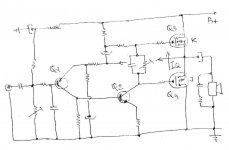
BTW. This is the JLH I like if wanting something big that is nice, I mentioned it before. Isn't JLH a modest writer. The MOSFET construcntion he talks about took me by surprise. I knew a little of it as the souce-drain in reverse bias is complex.
John Linsley Hood
John Linsley Hood
Nige
Appreciate very much JLH work&designs but I don`t understand why hi used BJT/LatFet hybrid CFP pairs for OPS ? , same performance can be achieved with conventional 4 transistor approach , where OPS FET pair is driven directly from VAS stage , maybe I`m wrong but I think that you have presented similar simple design somewhere .
BTW , I`m still convinced that very good sounding SE or PP tube amp can be done in common grid configuration , with output power tube grid tied to ground and cathode driven via small Jfet`s .
Regards
Attachments
The Kitic saga was largely before my time, but the last time I replied on one of his RH threads here, and myself trying to stay neutral even, he was absolutely adamant that no FFT need be taken to see what the RH results really were. His Spice simulation was the last word, and that was it. So all arguments were endless theoretical ones.
Not seeing any pentode in the triodes here, but I certainly do see the triode in the pentodes. For me, the pentode is just a triode with separated output and feedback (screen) terminals.
Analyzing the RH circuit with a triode driver, there are some subtleties. Its true that the triode driver Rp is varying, and so varying the N Fdbk ratio. Normally this would be bad news. However, the effect is benign in this case if controlled correctly.
When the output tube is reaching high current, with low Rp and high gm, the driver Rp is going high so that more N Fdbk is allowed to tame that aggressive output. Similarly, when the output tube is near turn-off, with high Rp and low gm, the driver Rp is going low, to reduce N Fdbk, so assisting the weak output tube to go further off. This is 2nd harmonic cancellation. The RH miracle 12AT7 driver triode has strong Rp variation (compared to constant Mu triodes). It is likely this was cancelling 2nd Harmonic of the output tube. But with no tests allowed, and cancellation denied, we'll never know. I'm not surprised there are hard feelings all around.
Last edited:
I put together a bench setup to do some SE amp experiments. After my current line of experiments I wanted to do comparative distortion tests on an RH-style 12AT7 driver amp and one with a 6AU6 driver. It's the next thing on my list.
When SY was here, we tested this amp on his bench. On half power, about 40W, we saw only -80 dB of the 2'Nd order harmonic, the rest was under the noise floor. However, close to 80W the tail grew up. The amp had nested feedback, i.e resistive dividers from anodes of output tubes, driven by a LTP pentodes.
http://www.wavebourn.com/forum/download.php?id=123&f=7
http://www.wavebourn.com/forum/download.php?id=123&f=7
Nige
Appreciate very much JLH work&designs but I don`t understand why hi used BJT/LatFet hybrid CFP pairs for OPS ? , same performance can be achieved with conventional 4 transistor approach , where OPS FET pair is driven directly from VAS stage , maybe I`m wrong but I think that you have presented similar simple design somewhere .
BTW , I`m still convinced that very good sounding SE or PP tube amp can be done in common grid configuration , with output power tube grid tied to ground and cathode driven via small Jfet`s .
Regards
Sorry to other to discuss this when about valves. The Better MOS FET amps should please people here. I think the link with FET's and pentode is small when power stages. It's the way they simplify a circuit I like. That circuit you show is so like one I did.
The JLH design is remarkable when it's time frame is taken into account. He goes back to capacitor coupling is one reason to say that. The 1980 amp is a little bit like a Quad 303. It was a triple using fast TR1 and then ultra industrial MJ Darlingtons. The MOS FET's do the same job as the Darlingtons. The beauty of the JLH is the VAS has less work to do, less than most preamps really ( can be 2 mA ). The output stage is a bit like the Schade idea in having local feedback. No long tail pair input which forces a better distortion balance. Like the 303 it is very low. It also avoides the VAS cDom stability idea which I suspect causes touble. I call it the one legged cyclist. I recently updated the PW Texan and got it to work ( use similar idea,voltage gain of 3 to 4 I find best ). I was given some 1935 Practical Wireless and Television. I think I see 1935 as a very modern time. The war put a stop to it. The written stuff is very modern and wise. The £4 Superhet and the WB Stentorian speaker. WB made the Quad ii output transformer ( I might be one of the few that know, Ross Walker told me and I spoke to WB who no longer did audio ) and I guess the ESL transformer. The WB had a built in transfomer. Loudspeaker outputs were at HT.
Last edited:

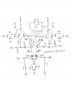
Here is a concept for Schade PP. I adapted the Dynaco ST70 circuit and just used a Philips ECC82 circuit in place of the 7199. The 7K8 might not be correct as it was hard to read. The other is the simplest Schade idea I found except I don't show LM317 CCS to EL34/KT88 cathode. Williamson prefered a shared resistor. Beam symbol used as it looks nicer. I prefer the EL34. The HT and 470/560R are starting values.
The ECC82 gain of 11 is possibly too high. Not using the ECC82 cathode capacitor is an option if so. However this should work directly via a volume pot on old radio tuners and similar as is. Remember that although the gain of the phase splitter is 1 and - 1 the differential gain is 2. The Schade circuit with ECC81 possibly has a gain of 12. This further drops when a Paraphase type. There is much cancellation of 2nd harmonic distortion also when the Paraphase. In transistor designs it can be nearly 100%. I suspect the Dynaco type will maintain the balance a bit better.
The ECC81 Paraphase Splitter ( Valve Wizard ) I suspect would give an input sensetivity of about 4Vrms at my bet guess. If the EF86 could be 1/2 of an ECC82 that might serve well. I dare say a hybrid with DC coupling could be made.
Not sure we call that one a paraphase. I always called it long tail pair. The other is mildy like the Williamson. Looks like the simple Philips circuit is almost good enough and in the spirit of the Schade amp. Here is an interesting analysis.
Practical Phase Inverters.
I should have said that the Philips ECC82 circuit is DC coupled valve one to valve two. Always note the grid voltage of valve number two before making modifications. The new circuit must be close to the old one to have a chance of working. Doubless Philips took much trouble to get it right. On second thoughts I would pot down the volume to the amp if it was too loud. Initially that is. 12BH7 mentioned in the above text is a nice device.
Last edited:
Nige
I think that your concept of Shade Fb on that A-class PP amp is very good ,
but I will maximize driver stage voltage gain before Shade Fb is applied ,
btw , what you think if `Shaded` EL34 PP-OPS works with fixed G1` negative bias closer to economic a/B class with let`s say B+650V and B+G2= 325VDC and with 6SL7 driver stage ?
Attachments
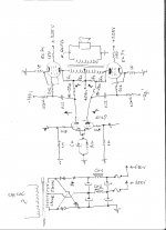
A QQV03-20A or QQV07-50 Audio Amplifier
Here is a very interesting circuit using 12BH7. Note how R10 and 11 are arranged to suit a shorter tail than is ideal. I like the output device. Repalce the EF86 if with this amp. 12BH7 and ECC82 often will transpose.
Here is a very interesting circuit using 12BH7. Note how R10 and 11 are arranged to suit a shorter tail than is ideal. I like the output device. Repalce the EF86 if with this amp. 12BH7 and ECC82 often will transpose.
R13=47k 😕 and the finals cathode short circuited to ground in the second schematic 😱A QQV03-20A or QQV07-50 Audio Amplifier
Here is a very interesting circuit using 12BH7. Note how R10 and 11 are arranged to suit a shorter tail than is ideal. I like the output device. Repalce the EF86 if with this amp. 12BH7 and ECC82 often will transpose.
I hope no newbe try to build those things.
Mona
Nige
I think that your concept of Shade Fb on that A-class PP amp is very good ,
but I will maximize driver stage voltage gain before Shade Fb is applied ,
btw , what you think if `Shaded` EL34 PP-OPS works with fixed G1` negative bias closer to economic a/B class with let`s say B+650V and B+G2= 325VDC and with 6SL7 driver stage ?
Wouldn't it be nice if it got built. I am moving house soon. My big baffles are taken down and just an Armstrong 625 with Mission 760's to use. It won't be me this year. I have a PSU built of nice junk housed in a decking wood plinth, looks good and very cheap. It has a melamine top ready for valve basses. I then have some EL34 UL PP transformers I can use. The PSU is very quiet. Tested into series 100 watt 230 V lamps which seem to be an exact clone EL 34 load at 470VDC/2! The heaters are 3.15-0-3.15. I only found 2 dB noise reduction using DC. Even that was at 50 Hz. At 100 Hz they were the same. As 100 Hz is the problem no real advantage ( hum - 83 dB below 1 watt, heater and HT ). Don't be fooled into thinking DC is better, also it brings problems some say ( I have no idea ). This was on my SE design. When PP it could be better. The PSU is a FET capacitance multiplier. Without it, it has no hope of working with my 100 dB/watt speakers. The SE in PP out design was only - 60dB hum without it.
In UL I am told we should not run above 500VDC as at times the voltage seen is above the 800VDC safe working due to effects of cross coupled EL34's ( TT21 should be OK ). I had a Siemens Berlin cinema amp which in the UK ran at 820V ( 246 VAC UK against 227 VAC Berlin ). I really liked it's raw sound. The voltage on cheap National EL34 did not kill them. Two pentode that might have been EF41 and two EL34. The phase splitting was by long tail pair with 9 dB of loop feedback. 1.3 % distortion at 10 watts and 13 % at 100 watts ( fixed bias I think and standby mode, Class AB2 I think ? ). At 1 watt it was not bad. The EL34's ran with raw DC at the anodes and the G2 etc highly choke filtered. The blue colour in the EL34's said it was having a party inside the bottles ( not the best vacuum ). As you say 650VDC could work in pure pentode. The output transformer had a tap that could run 8 ohms. Test mode or in the projection room I guess. Circa 1958. As far as I remember the HT was at 600V on standby. What ther G2 the other voltages did I don't remember. The current was greatly reduced. I hope Frank still has it. As he really loves Siemens of his home city I think he might. I refused to change how it worked.
R13=47k 😕 and the finals cathode short circuited to ground in the second schematic 😱
I hope no newbe try to build those things.
Mona
I see what you mean. For once it's not me. HT and newby's would be my big doubt. You would be surprised how many Sony service manuals were no better. When Sony made the TV9-90UB and TC377 they looked like junk inside and yet were nearly 100% reliable. After that........... The TV9-90 looked like it had been repaired when new. It never gave trouble! Leak amplifers also before Rank killed them.
Nige
For maximum output power& long life those EL34 likes high voltage B+ and 1/2 B+ G2` biased in economic a/B class ,
ratio of R1/R2&R3/R4 can determine applied Shade Fb percent ,
B+ PSU can be done with small two isolation transformer 240V~/240V~ and with secondaries connected in series .
For maximum output power& long life those EL34 likes high voltage B+ and 1/2 B+ G2` biased in economic a/B class ,
ratio of R1/R2&R3/R4 can determine applied Shade Fb percent ,
B+ PSU can be done with small two isolation transformer 240V~/240V~ and with secondaries connected in series .
Attachments
Last edited:
The Trioderizer - a solid state triode
As i mentioned tested it, works good.
Comp cap very important to have right value - if schematic has big U swing and supply, often fet Cgd value moves much (Uds/Cgd)
You have difficulty to pick right value
As i mentioned tested it, works good.
Comp cap very important to have right value - if schematic has big U swing and supply, often fet Cgd value moves much (Uds/Cgd)
You have difficulty to pick right value
Nige
For maximum output power& long life those EL34 likes high voltage B+ and 1/2 B+ G2` biased in economic a/B class ,
ratio of R1/R2&R3/R4 can determine applied Shade Fb percent ,
B+ PSU can be done with small two isolation transformer 240V~/240V~ and with secondaries connected in series .
The g2 voltage depends on the loading and its upper limits. this 'half' number is just a guess...and not too useful at all.
cheers,
cheers,
Douglas
Hi Douglas
Check Philips or TFK EL34 datasheet for PP 100W in pentode mode , they suggest 800V/400V , even Tung Sol 6550 suggest 600V/300V for PP 100W ,
after all I have made two unit based on Philips/TFK application note , one was RF/AM modulator with 4xEL34(KT90) with 850V/425V and second was
one Marshall SL clone with 4xEL34 750V/375V , those EL34 last and last.
Regards

Were it not for the Quad ii I would never have thought of this. Also Richard Brice when he first said a Cascode would be an alternative to a pentode. This was long before I had an email account.
The concept is only to say could more be had from our valves and a higher Rp without buying a long obsolete pentode. I have some experiance with transistor cascodes and must say they just work without any touble. My very few experiments with valve cascodes needed more thought. A double ECC82 being OK. Here we can have an ECC81 + ECC82 or whatever or all the same. Perhaps 2 x ECC88 still has an Rp in the target area.
~ Triode Cascode Amplifier Calculator ~
One could say the signal path is shorter. It's almost true is we see the cathode coupling as harmless. As no loop feedback is used I feel it qualifies.
As you can see you can use what you like. It is very possible even if you do the worst idea you can it will beat a single ECC81. One possibility is the gain can be higher whilst Rp also higher. The rest is how the final distortion balance works out. I dare say the tail resistor could be to a -ve rail and the biasing for a real version would be different.
- Status
- Not open for further replies.
- Home
- Amplifiers
- Tubes / Valves
- Schade Feedback In A Push Pull Differential Amplifier?