Dear Alex,
Although I have build the most part of RTP3C, for years now I never managed to sit down and finish it completely. Too many projects, too many obligations, so little time. I only quote what Allen had written to me. Whenever I complete my RTP3C, I will be able to check it myself and report back.
Regards,
Evangelos
Geia sou Evangelos,
As I said earlier in the thread, one great thing about the RTP3 is that it is modular, so you can build and test sections individually. On top of that, the point-to-point wiring (except in the very latest versions) means that trouble-shooting and fixing mistakes is much easier than with a PCB. Actually, despite its complexity and the ridiculous number of valves, my build was pretty trouble free compared with some other projects of mine - the only hassles I had were with the shunt regs (I should have gone with Allen's SuperRegs from the start) and with the filament current regulation.
I hope that you are able to compete this project and enjoy it before too long. This really is a very special preamp.
Alex
Geia sou Alex,
I'm aware of all these things you are referring to. But, since I'm currently using Allen's FVP5 preamp and I'm happily living with it, I'm too lazy to finish my RTP3C. Of course, I know that it is a league above comparing to the FVP5, so that's what will prompt me to complete it eventually.
Best regards,
Evangelos
Yes, the FVP5/SVP is an excellent preamp, and I am pleased with the one I built. My only complaints are excessive gain in the line stage (I got around this to some extent by replacing the 6922 in the voltage amplifier stage with a 5687, and will further reduce it when I get time by adding an LED in parallel with the cathode resistor, as suggested by Joe Rasmussen), and some hum, despite having an outboard PSU.
Is yours a VSE kit or did you collect the parts yourself?
Alex
sreg current
Hello,
as a longtime rtp owner builder (done from scratch with some help from allen)
mine is running 330V dc in the sreg and 18mA of shuntcurrent, and it runs very hot and i^m using a heatsink nearly double the height than delivered with the kit-so I would stay below 20mA(sreg was the only kitpart I bought)
greetings from Vienna
klaus
Hi Klaus,
What are the input and output voltages on the regulator? 330V seems too low for input, and too high for output.
Power dissipation in the series MOSFET is (Iload+Ishunt)*(Vin-Vout), and in the shunt MOSFET is Ishunt*Vout. In mine, once the preamp has stabilised and drawing the rated B+ current, which takes a minute or so, these are around 4W and 6W, respectively, and the heatsinks get warm to the touch, but no more than that. While the valves are warming up (which takes about a minute), the series MOSFET has the whole of Vin across it and the dissipation is about 7W for a short time, but this isn't excessive. I wonder whether there is something wrong with your setup?
Alex
Hi Frode,
Referring to your question under #614 whether to choose 355 or 380 V at the input of the Sreg I can tell you the following from the RTP3D power supply instructions.
The power transformer is specified 420 V AC secondary and it will measure ca. 590 V DC at the output and that is behind the LCRCRC chain without a bleeder and without any load ( idle ) !!
As soon as the load ( the two Sregs ) are connected this voltage will drop to ca. 360 V DC so 355 V should be all ok. Hope that clarifies things completely.
Looking at the pictures of your preamp I also have a question. What is the purpose of those two copper boards located below the original metal phono boards at the back side of the preamp?
This I guess is your own construction as they are not shown in the instructions.
Initially I thought since I can see a pot on the topside that these are meant for impedance or gain adjustment however when looking at the photograph of the backside
I noticed three transistors there as well.
Did you place some parts originally meant to be located on the phono metal boards on these additional copper boards due to space restrictions or why these additional boards
I'm asking myself.
Thank you very much
Regards
airtangent
In mine, once the preamp has stabilised and drawing the rated B+ current, which takes a minute or so, these are around 4W and 6W, respectively, and the heatsinks get warm to the touch, but no more than that. While the valves are warming up (which takes about a minute), the series MOSFET has the whole of Vin across it and the dissipation is about 7W for a short time, but this isn't excessive. I wonder whether there is something wrong with your setup?
Alex
To overcome this issue, I have added a delay circuit which connects the HV transformer to the mains voltage, 45 seconds after the switch-on of the preamp, until the heaters of the tubes (valves) have been heated enough to emit electrons. Of course, this approach assumes that one has an individual transformer just for B+. And, as you already know, this is not actually tested in practice.
Evangelos
That's puzzling. A TO220 device on a large heatsink dissipating 7W or less should certainly not get "very hot", and you have half the voltage across the series MOSFET I have, so should get half the heat out anyway. Which of the two heatsinks gets the hottest? Did Allen comment on the fact that you were having to use such a low shunt current? I wonder whether there is an instability in the regulator.no everything fine with my setup, it was also checked in Allens Lab long time ago
I have 330 DC input (with very low ripple because I use a 3 phase valve rectifier) and 300V DC ootput of the superreg, and I removed based on allens rec. the series lm317
Yes, I did this mod a few months after I installed the SuperRegs in mine. I can't say I heard any improvement, but at least I have a pair of spare LM317s now
")
Just out of interest, how does the VSE kit supply the +15V supply to the opamp in the regulator? Is there a regulator board in the PSU box? I ended up drilling holes in the SuperReg boards for an LM317 series regulator.
Alex
Last edited:
Hi Frode,
Referring to your question under #614 whether to choose 355 or 380 V at the input of the Sreg I can tell you the following from the RTP3D power supply instructions.
The power transformer is specified 420 V AC secondary and it will measure ca. 590 V DC at the output and that is behind the LCRCRC chain without a bleeder and without any load ( idle ) !!
As soon as the load ( the two Sregs ) are connected this voltage will drop to ca. 360 V DC so 355 V should be all ok. Hope that clarifies things completely.
Looking at the pictures of your preamp I also have a question. What is the purpose of those two copper boards located below the original metal phono boards at the back side of the preamp?
This I guess is your own construction as they are not shown in the instructions.
Initially I thought since I can see a pot on the topside that these are meant for impedance or gain adjustment however when looking at the photograph of the backside
I noticed three transistors there as well.
Did you place some parts originally meant to be located on the phono metal boards on these additional copper boards due to space restrictions or why these additional boards
I'm asking myself.
Thank you very much
Regards
airtangent
Hello Airtangent !
Thank you for advice and information !
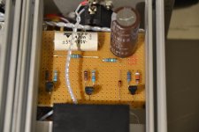
The Board behind the phonostage and in front of the Sreg are the -24 minireg and ccs. As it was so litle Space for all this parts at the original location, I removed them on a separate plate. To build them as modules out side the chassi, made it a bit more easy. The 3 transistors at each modul are Bss 129.
I have also fitted 330 uf at each section, and 2 x 330 uf at line section.
Sincerely
Frode
Last edited:
Airtangent !
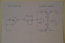
I forgot to explain about the trim pot I have on these circuit board. As I understand it, the current throu the negative 24 v supply, sets the anode voltages on tube B in the linestage. By increase or decrease the current with a trim pot, you can adjust for exactly 150 v in the line stage, and 65 v in the phono.
I made a schetch to show you were I placed it. If you look at the number of parts at the picture, you wil se it corespond with the drawing.
At the time I ordered parts for the rebuild, I was thinking that a 25 turn trimmer have 5 turns for 1 k, plenty adjustments possibility. To be 100 % certain I did not have to litle resistance, I bought 5 k trim pots. If I were to buy it today, I would have chousen 500 ohm, as I think this is enough resistanse and the acuaracy of the adjustment are more easy.
The blue trim pots next to LM 317 for the heater is 10 ohm. I found out that using a smal circuitboard in front of the pot, made the connection of cable to it easy. When incerting a cable in the houl, it stays tight to the pot leg when solder. It also work great as isolalater between the legs.
I have ordered resistors to end up with about 360 v as "in" volt to Sreg, as you mentioned. My total B+ supply wil be: 10H- 50uf- 100 ohm- 50uf- 100 ohm- 100uf- 220+500 ohm- Sreg- 120 uf
Sincerely
Frode
Attachments
I see I forgot the 24 v zener before the 5k pot
Attachments
I see I forgot the 24 v zener before the 5k pot
It's not at all obvious to me what the pot does! Its function appears to be to insert a variable resistance in series with the CCS, and I don't understand why one would do that.
I would have thought a more useful control would be on the CCS current, and the pot in that position certainly doesn't do that.
Alex
Last edited:
Hello,
Allen himself wrote in his book that the best thing to do was using a shunt supply to get the reference voltage for the main supply.
Later he also published about replacing the 317 regulator by a pair of resistors.
Greetings, eduard
In my SuperReg schematic (packaged with my kits three years ago, but dated 2001!) the voltage reference is an LM329 precision 6.9V zener, which is probably good enough.
Yes, the manual in mine included the "317 begone mod", which I applied after a few months. As I said earlier, I didn't hear any significant difference.
Alex
Last edited:
Hello,
Replacing the standard 15 voltage supply with the Tentlabs supply was a big improvement. So was the 317 begone mod which i did in several of the superregs i am using.
One of the easiest modifications to do is getting an input choke with more Henry. The best i found so fat ( and i have tried a few!) are the Lundahl chokes connected in common mode.
Greetings, Eduard
Hello,
Replacing the standard 15 voltage supply with the Tentlabs supply was a big improvement. So was the 317 begone mod which i did in several of the superregs i am using.
One of the easiest modifications to do is getting an input choke with more Henry. The best i found so fat ( and i have tried a few!) are the Lundahl chokes connected in common mode.
Greetings, Eduard
Perhaps I will try a shunt reg on the op-amp supply some time - I can imagine an LM317 could be bettered.
When you say "input choke", do you mean on the HT supply or the ShuntReg op-amp supply?
Alex
Hi Frode,
Thank you for sharing with us the buildup of these seperate copper boards.
My only concern here with these boards is that in case of the phono amps you put them between the metal phono boards and the rear panel.
Considering the fact that phono is the most sensitive part in a preamp ( mV signals )
I would have made the phono board input wiring to the rear jacks as short as possible
and then in my opinion it would have been better to place these seperate copper boards
in front instead of behind the metal phono plates. This will keep wiring between input on the phono board and phono jacks ( Cinch, XLR or Redel ) very short.
This is what is usually done so as well in the RTP3 preamp, see here a photograph from a current manufacture RTP3E ( latest version ):
Vacuum State RTP3 preamp Photo #1073042 - US Audio Mart
You could then easily take the required 29V input voltage from the copper board in front of the Sregs.
Just an idea.
Sincerely
Günter
- Home
- Amplifiers
- Tubes / Valves
- Vacuum State RTP3C