Hello Gunter !
Thank you for Your thougts and idea. It was also very intresting seeing photo of the latest version of the RTP 3.
The boards I have used is some kind of plastic/papir combination. Only a thin copper foils around the houls to solder on. The total mass of copper is very smal.
Al the parts I have placed on these circuit boards are original placed on the two (9 tags ) cheramic strips next to the tube. The reason I moved the parts, was that I understood that With my skils, I would not be able to place so many parts at this smal place and make it look neat and nice. I am not shure if remowing thouse parts between the metal phonoplate and Rca/xlr input wil have a negative inpact/ efect on the noice. I wil certainly have it in my mind.
Sincerely
Frode
It's not at all obvious to me what the pot does! Its function appears to be to insert a variable resistance in series with the CCS, and I don't understand why one would do that.
I would have thought a more useful control would be on the CCS current, and the pot in that position certainly doesn't do that.
Alex
Hello Alex !
The adjustable resistor was something Allen told me was a trick he used. The values in the schematics are theoreticly perfect. As each induvidual kit vary slightly,they need to be fine trimmed to have the exact voltages as in the schematic.
It is about 20 years ago, so I cant remember word for word, but he used a trimmer to get 150 v on line and 65 v on phonostage. Then he cut out the trimmer and mesured it, and soldered in a fiksed resistor of that value.
When I desided to rebuild my amp, I cut out all resistor, capacitor and some wire. From what you say, I start to wonder if I placed this adj resistor in wrong lokation when rebuilding it.
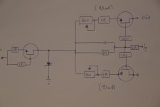
Alex, the line and phono have the same negative power supply. The minireg and ccs are the same, exept that line have 2k in front of the Bss129 and phono have 1,32k. It looks like lower resistanse in front of the Bss129 increase the current and gives lower volt on plate, versus higher r give higher volt. (2k = 150 v) (1,32k = 65 v )
By placing a variable resistor in front of the 2k and 1,32k, it is posible to manipulate the value of the 2k or 1,32k. This is how I understand it. If I am right is often the opposite 🙂
Hello Eduard !
When I bought the Sreg kit, and read about this removal of LM 317 improvment, I was thinking to do this upgrade my self. But the description in the manual was a bit complicated for me to understand, so I buildt it as the original schematic shows. I understend much faster and bether if I can see it in a schematic, insted of just eeading it. As you probably have understand by reading my English writing, is that I am not working as a English teatcher or as a translator 🙂
What are the Sreg out volt on the one you have done the modificasjon on ? Do you have a photo or a drawing of the change ?
Sincerely
Frode
Hello Alex !
The adjustable resistor was something Allen told me was a trick he used. The values in the schematics are theoreticly perfect. As each induvidual kit vary slightly,they need to be fine trimmed to have the exact voltages as in the schematic.
It is about 20 years ago, so I cant remember word for word, but he used a trimmer to get 150 v on line and 65 v on phonostage. Then he cut out the trimmer and mesured it, and soldered in a fiksed resistor of that value.
When I desided to rebuild my amp, I cut out all resistor, capacitor and some wire. From what you say, I start to wonder if I placed this adj resistor in wrong lokation when rebuilding it.
Alex, the line and phono have the same negative power supply. The minireg and ccs are the same, exept that line have 2k in front of the Bss129 and phono have 1,32k. It looks like lower resistanse in front of the Bss129 increase the current and gives lower volt on plate, versus higher r give higher volt. (2k = 150 v) (1,32k = 65 v )
By placing a variable resistor in front of the 2k and 1,32k, it is posible to manipulate the value of the 2k or 1,32k. This is how I understand it. If I am right is often the opposite 🙂
Frode,
I think your schematic in post #633 must have a mistake. I agree that you need to fine-tune the CCS currents to get the correct anode voltages but what need to be adjusted are the 2K (or 1K34) resistors, since these are what control the current, and individual JFETS will have slightly different parameters.
What I did was to reduce the value of each of the resistors (say 1K32 -> 1k0) and put a variable resistor (say 500R) in series with it, adjusting this to give the correct voltage across the fixed resistor. So for the phono stage CCS, for instance, you would aim to get 9.5V across a 1K0 resistor for a 9.5mA current. Putting the pot between the "mini SuperReg" and the CCS won't do anything at all except dissipate heat.
Alex
Last edited:
15V supply for opamp
Hi Alex,
No there is no regulator board in the PSU box of the RTP3D, only unregulated voltages are supplied feeding the preamp.
For the +15 Volt the low heater supply is used.
So the voltage for the opamp is std. not regulated and if one wants to use a regulator it must be added individually.
Sincerely,
Günter
Thanks, Gunter. That's interesting - I am surprised Allen put an unregulated supply there, given he has been quoted as recommending a shunt reg in that position.
Alex
lets define hot
I think its around 50 degree Celsius at the shunt heatsing, series part doesn't get very hot
I think its around 50 degree Celsius at the shunt heatsing, series part doesn't get very hot
Hello,
Allen wrote that the quality of the completely supply depends a lot of the quality of the 15 volts. Because it just takes a very low current there are numerous ways to do it. I think the best one to use also a shunt circuit fed by a choke input. It is a crime to install if you want it as close as possible to the circuit. Better install it where you have some more space.
Greetings, Eduard
Attachments

Hello !
Today I tested the Sreg. It was posible to adjust volt (P2) and mA (P1), but the lamp did not come on in any of the Sreg. I adjusted them to 300v and 100 mv.
Is it posible to put the lamp the wrong way ?
Out from the + 30vdc supply to the Sreg I have 34,5 vdc, and on the + 15 v on the Sreg I have 33,7 and 33,9vdc. On the description there are specified 100 ohm between the 30 v supply and each Sreg. On my personal manual, it is hand written " 51 ohm " I have used 51 ohm to each Sreg.
0,7 and 0,5 v drop is very litle, its all moust as the circuit dont draw any current.
Any sugestion about what might be wrong ?
Sincerely
Frode
Attachments
Last edited:
Hello,
Yes indeed as well in the TPCB as in the instructions of the Sreg Allen emphasized that the supply to the opamp is critical as this forms the reference for the output.
He also mentioned that commercially he would use a LM317 although then it is very strange that there are no provisions on the Sreg PCB for applying this since from the RTP3D power supply only unregulated DC voltages are fed to the preamp.
A bit inconsequent in my opinion.
The same is true for the big 22uF cap at the output of the current source part of the Sreg where still an electrolytic capacitor is used although the HV power supply in the RTP3D is no longer using electrolytic caps anymore.
In the description of the RTP3D on the website the use of polyprop filter caps for the HV power supply among others is mentioned as the biggest change and improvement over previous RTP models!
But ok everybody is free to change that individually although a 22uF MKP or alike will definitely not fit on the PCB anymore!
Regards,
Günter
Hello,
Yes indeed as well in the TPCB as in the instructions of the Sreg Allen emphasized that the supply to the opamp is critical as this forms the reference for the output.
He also mentioned that commercially he would use a LM317 although then it is very strange that there are no provisions on the Sreg PCB for applying this since from the RTP3D power supply only unregulated DC voltages are fed to the preamp.
A bit inconsequent in my opinion.
The same is true for the big 22uF cap at the output of the current source part of the Sreg where still an electrolytic capacitor is used although the HV power supply in the RTP3D is no longer using electrolytic caps anymore.
In the description of the RTP3D on the website the use of polyprop filter caps for the HV power supply among others is mentioned as the biggest change and improvement over previous RTP models!
But ok everybody is free to change that individually although a 22uF MKP or alike will definitely not fit on the PCB anymore!
Regards,
Günter
I'm in complete agreement, Günter - I had a double-take when Allen talked about using a large electrolytic to stabilise the SReg, when he insisted elsewhere in the TPCB that anything across the HT line should be considered in the signal path. My SRegs are basically stock, with the electrolytics installed as supplied with the kit. And no, there definitely isn't room for a 400V 22uF PP on the board!
I think the minimum regulation for the opamp is an LM317, and there is space on the board for one of those, so that's what I did.
Alex
Hello !
Today I tested the Sreg. It was posible to adjust volt (P2) and mA (P1), but the lamp did not come on in any of the Sreg. I adjusted them to 300v and 100 mv.
Is it posible to put the lamp the wrong way ?
Out from the + 30vdc supply to the Sreg I have 34,5 vdc, and on the + 15 v on the Sreg I have 33,7 and 33,9vdc. On the description there are specified 100 ohm between the 30 v supply and each Sreg. On my personal manual, it is hand written " 51 ohm " I have used 51 ohm to each Sreg.
0,7 and 0,5 v drop is very litle, its all moust as the circuit dont draw any current.
Any sugestion about what might be wrong ?
Sincerely
Frode
In my SuperReg kits the indicator is a little incandescent lightbulb, which will work either way round. I expected mine to glow at startup, but there is in practice very little glow from it.
I don't understand what you mean by the +30V and 15V supplies? Mine only has the HT input and "Low V 12-36V", which I fed with a regulated 15V. And where are the "voltage drops" you mention?
Alex
LM317 opamp regulator
Hi Alex,
I suppose that you made use then of the tweak called "The 317 be gone mod" which replaces the LM317 current source with a resistor, right?
One could leave then the already existing LM317 on board and with some improvisation work by making use of flying leads and adding the necessary resistors this LM317 would form the series reg for the opamp supply.
The reqired replacement resistor for the current source could then be soldered on the backside of the board.
That would at least be my idea and has the advantage that no additional LM317 with space requiring heat sink needs to be placed on the PCB.
Is that what you actually did?
Maybe a photograph of your solution would be nice, thank you.
Regards,
Günter
I think the minimum regulation for the opamp is an LM317, and there is space on the board for one of those, so that's what I did.
Alex
Hi Alex,
I suppose that you made use then of the tweak called "The 317 be gone mod" which replaces the LM317 current source with a resistor, right?
One could leave then the already existing LM317 on board and with some improvisation work by making use of flying leads and adding the necessary resistors this LM317 would form the series reg for the opamp supply.
The reqired replacement resistor for the current source could then be soldered on the backside of the board.
That would at least be my idea and has the advantage that no additional LM317 with space requiring heat sink needs to be placed on the PCB.
Is that what you actually did?
Maybe a photograph of your solution would be nice, thank you.
Regards,
Günter
Hello Alex !
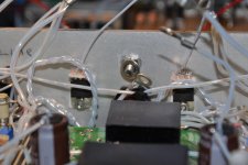
If you look at the Picture of this post, there are two resistors coming up from +15 v on the Sreg. On the top of them I have 34,5 v, and on the Sreg I have about 33,7 and 33,9 v. The drop over each of the two 51 ohmresistors are about 0,5 v.
In my Power supply I have a 24 vac transformer with 2 secundary. One is for the negative 24 vdc supply, and the other is for the +15 v to Sreg. After rechtifiers and capacitors, the volt here is 34,5 vdc.
I would have guesed that having thouse two 51 ohm resistors was to drop the volt from 34,5 to around 15 v. When there are only 0,5 v drop, my Instinct told me that there must be someting wrong !?
Last night I read the Sreg kit instruktion again about the 15v supply from 9 Nov. 1999. Quote: The low voltage supply can be from 12vdc minimum to 36vdc Maximum- prefererably well regulated. This can be from a regular LM317 type chip series regulator- there is no benefit observed in using another shundt regulator here. ( This last section is remowed from the 2001 instruction )
Last night I started to install two LM317 in the back of chassi. One for each Sreg. Here is a few Picture of my solution Gunter.
Sincerely
Frode
Attachments
Last edited:
1/QUOTE]
Attachments
I suppose that you made use then of the tweak called "The 317 be gone mod" which replaces the LM317 current source with a resistor, right?
One could leave then the already existing LM317 on board and with some improvisation work by making use of flying leads and adding the necessary resistors this LM317 would form the series reg for the opamp supply.
The reqired replacement resistor for the current source could then be soldered on the backside of the board.
That would at least be my idea and has the advantage that no additional LM317 with space requiring heat sink needs to be placed on the PCB.
Is that what you actually did?
That's a good idea, but it's not what I actually did! One reason is that I hate hacking around with someone else's PCB traces, and the other reason is that I set up the SuperRegs with the LM317 in the CCS to start with (this is actually what Allen recommends in the SReg manual). As it happens, you can't do the Begone Mod until you know what the total current through the CCS is, so you need the low-voltage regulation for the opamp to get the whole regulator going in the first place.
Maybe a photograph of your solution would be nice, thank you.
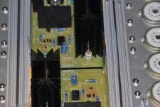
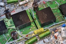
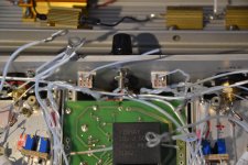
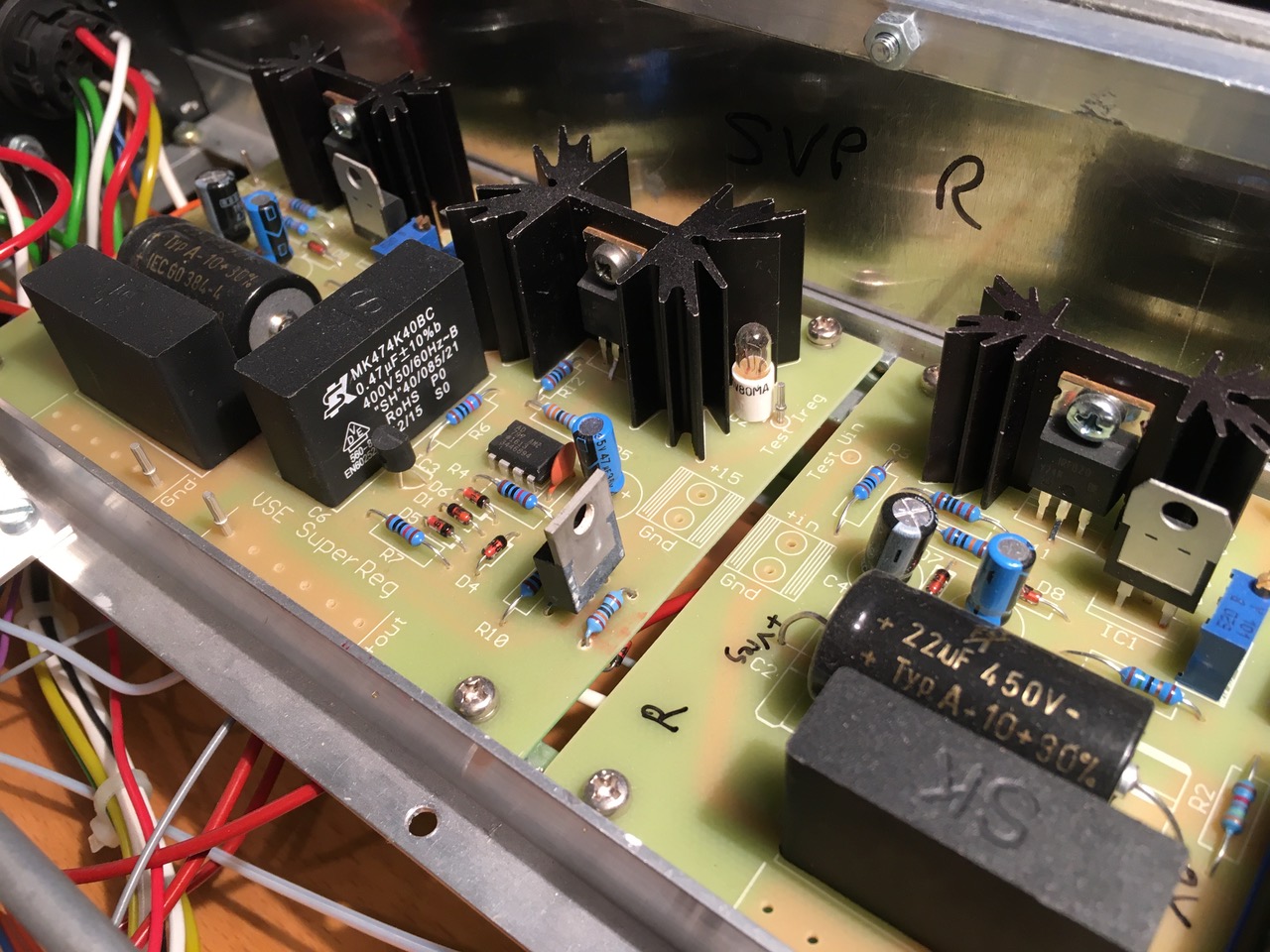
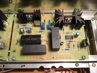
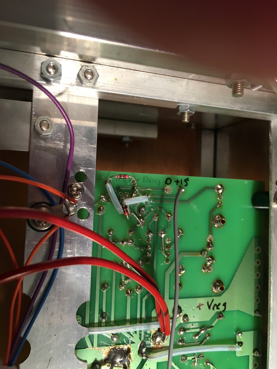
OK, here are three photos of the SuperRegs in my SVP. The original LM317s are still there (in front of the left-hand heatsinks), as I have only made the Begone mod so far to the ones in my RTP3. You can see where I mounted the second LM317 in the front right corner, and get some idea of the connections under the board too. You just need to drill holes for two resistors for each chip reg; the diodes underneath are unnecessary in this case, apart from mechanically securing the TO220 devices.
Alex
Hello Alex !
If you look at the Picture of this post, there are two resistors coming up from +15 v on the Sreg. On the top of them I have 34,5 v, and on the Sreg I have about 33,7 and 33,9 v. The drop over each of the two 51 ohmresistors are about 0,5 v.
In my Power supply I have a 24 vac transformer with 2 secundary. One is for the negative 24 vdc supply, and the other is for the +15 v to Sreg. After rechtifiers and capacitors, the volt here is 34,5 vdc.
I would have guesed that having thouse two 51 ohm resistors was to drop the volt from 34,5 to around 15 v. When there are only 0,5 v drop, my Instinct told me that there must be someting wrong !?
Last night I read the Sreg kit instruktion again about the 15v supply from 9 Nov. 1999. Quote: The low voltage supply can be from 12vdc minimum to 36vdc Maximum- prefererably well regulated. This can be from a regular LM317 type chip series regulator- there is no benefit observed in using another shundt regulator here. ( This last section is remowed from the 2001 instruction )
Last night I started to install two LM317 in the back of chassi. One for each Sreg. Here is a few Picture of my solution Gunter.
Sincerely
Frode
Hi Frode,
I don't understand your calculations for the op-amp supply. To get .5V across 51 ohms, you are drawing around 10mA, which is easily believable for an op-amp. To drop 19.5V the 51R resistor would have to be passing 380mA, which is a LOT for an op-amp!
I wouldn't recommend using a series resistor to feed an op-amp Vcc supply. I would strongly recommend a chip regulator, as this will have a much lower impedance. This seems to be what you are planning to do, which is good
Alex
/QUOTE]
... and I should add that you don't need to worry about mounting the supply regulator for the op-amp on the chassis. It should dissipate well under a watt, even if you drop 20V across it. If you are concerned, you can screw a small finned TO220 heatsink onto the chip.
Alex
- Home
- Amplifiers
- Tubes / Valves
- Vacuum State RTP3C